EP0778655A2 - Dispositif pour déplacer les balais de charbon dans un moteur électrique - Google Patents
Dispositif pour déplacer les balais de charbon dans un moteur électrique Download PDFInfo
- Publication number
- EP0778655A2 EP0778655A2 EP96118969A EP96118969A EP0778655A2 EP 0778655 A2 EP0778655 A2 EP 0778655A2 EP 96118969 A EP96118969 A EP 96118969A EP 96118969 A EP96118969 A EP 96118969A EP 0778655 A2 EP0778655 A2 EP 0778655A2
- Authority
- EP
- European Patent Office
- Prior art keywords
- contact
- carrier
- carbon brushes
- contacts
- electric motor
- Prior art date
- Legal status (The legal status is an assumption and is not a legal conclusion. Google has not performed a legal analysis and makes no representation as to the accuracy of the status listed.)
- Granted
Links
Images


Classifications
-
- H—ELECTRICITY
- H02—GENERATION; CONVERSION OR DISTRIBUTION OF ELECTRIC POWER
- H02K—DYNAMO-ELECTRIC MACHINES
- H02K23/00—DC commutator motors or generators having mechanical commutator; Universal AC/DC commutator motors
- H02K23/66—Structural association with auxiliary electric devices influencing the characteristic of, or controlling, the machine, e.g. with impedances or switches
-
- H—ELECTRICITY
- H02—GENERATION; CONVERSION OR DISTRIBUTION OF ELECTRIC POWER
- H02K—DYNAMO-ELECTRIC MACHINES
- H02K23/00—DC commutator motors or generators having mechanical commutator; Universal AC/DC commutator motors
- H02K23/02—DC commutator motors or generators having mechanical commutator; Universal AC/DC commutator motors characterised by arrangement for exciting
- H02K23/18—DC commutator motors or generators having mechanical commutator; Universal AC/DC commutator motors characterised by arrangement for exciting having displaceable main or auxiliary brushes
-
- H—ELECTRICITY
- H02—GENERATION; CONVERSION OR DISTRIBUTION OF ELECTRIC POWER
- H02K—DYNAMO-ELECTRIC MACHINES
- H02K5/00—Casings; Enclosures; Supports
- H02K5/04—Casings or enclosures characterised by the shape, form or construction thereof
- H02K5/14—Means for supporting or protecting brushes or brush holders
- H02K5/143—Means for supporting or protecting brushes or brush holders for cooperation with commutators
- H02K5/148—Slidably supported brushes
-
- H—ELECTRICITY
- H02—GENERATION; CONVERSION OR DISTRIBUTION OF ELECTRIC POWER
- H02K—DYNAMO-ELECTRIC MACHINES
- H02K11/00—Structural association of dynamo-electric machines with electric components or with devices for shielding, monitoring or protection
- H02K11/02—Structural association of dynamo-electric machines with electric components or with devices for shielding, monitoring or protection for suppression of electromagnetic interference
Definitions
- the invention relates to a device for adjusting the carbon brushes for a reversible electric motor according to the preamble of claim 1.
- Electric hand tools such as drills, screwdrivers or the like, are often designed for operation in both clockwise and counter-clockwise rotation, with an electrical switch for the polarity of the connections of the electric motor being arranged on the power tool.
- the carbon brushes can also be adjusted to the optimum position when the direction of rotation is switched.
- an electric hand tool with a reversible electric motor on which a device for adjusting the carbon brushes while switching over the Direction of rotation of the electric motor is arranged.
- This device consists of a fixed contact plate attached to the stator of the electric motor and a carrier which in turn can be pivoted on the contact plate.
- the brush holders for the carbon brushes grinding on the collector of the electric motor are attached to the carrier.
- the carrier is designed with a cavity in which switching contacts which are in electrical connection with the carbon brushes are arranged.
- the contact plate serves to accommodate fixed contacts, which in turn are connected to the connections for the field windings of the electric motor.
- the fixed contacts have contact surfaces which interact with the switching contacts as counter-contacts in an alternating contacting of the carbon brushes when the carrier is pivoted, which reverses the direction of rotation of the electric motor.
- a disadvantage of the known device for adjusting the carbon brushes and for switching the direction of rotation of the electric motor is that the switching and fixed contacts are complex. Furthermore, an additional effort is to be seen in the fact that a separate electrical connection between the carbon brushes and the switch contacts is necessary. This makes the device more expensive to manufacture and complicates its assembly. In addition, due to the additional electrical connections and the complex arrangement of the contacts, there is a high risk that incorrect switching and circuit failures occur. The known device is therefore not functionally reliable.
- the known device cannot be completely preassembled. So the carbon brushes can only be used during assembly on the electric motor. The assembly is complex due to several individual parts to be assembled simultaneously. Subsequent replacement of the carbon brushes, which are wearing parts on the electric motor, is only possible by disassembling and disassembling the device. As a result, this device also lacks serviceability.
- the invention is based on the object of designing a device for adjusting the carbon brushes and for switching the direction of rotation of an electric motor in such a way that the contact and functional reliability is improved.
- a simplified assembly of the device on the electric motor should be ensured.
- the device can be configured as a compact component, the component consisting of a carrier and a contact plate which can be assembled by means of snap and / or guide hooks.
- the contact system for the changeover switch is encapsulated by the component, so that particularly good dust protection, as is required in particular when used in electric hand tools, can be achieved.
- the contact surfaces of the fixed contacts are designed as elastically reproduced end sections of contact strips.
- the contact strips can be located in a groove in the contact plate, which is arranged on the side facing the carrier.
- the part of the free surface of the brush holder facing the contact plate which acts as a switching contact, is formed so as to protrude from the free surface, and it can be bent in one piece from the free surface.
- the switch contact is approximately perpendicular to the free surface and runs in the axial direction with respect to the electric motor.
- the fixed contacts are arranged approximately parallel to the switching contact, running in the axial direction in the groove, the contact surfaces having an elasticity in the radial direction. As a result, the switching contacts interact with the contact surfaces of the fixed contacts in the radial direction for making contact.
- the switch positions that can be set when the carrier is pivoted by the interaction of the switch contacts and the fixed contacts are detent positions.
- the detent spring can be formed in one piece with the free surface of the brush holder, for example as a stamped and bent part.
- a chamber open on both sides in the radial direction for receiving the brush holders can be integrally formed on the carrier.
- a retaining hook is formed on the chamber, which in turn engages in the manner of a snap element in a recess on the brush holder.
- the carbon brushes can be retained in the brush holder for securing transportation.
- these holding elements serve as an aid for mounting the device on the electric motor, since it is then possible to plug it onto the electric motor without the carbon brushes interfering.
- the holding element can be removed, for example by being broken off.
- connections for the field windings are exposed on the side of the contact plate facing away from the carrier, so that the electrical connection between the connections and the field windings can be established when the device is placed on the stator of the electric motor.
- the connections can be designed in a wide variety of ways, for example as a plug-in terminal, plug, wire connection, sleeve connection or the like.
- a receptacle for a radio interference suppression choke is arranged on the side of the contact plate facing away from the carrier.
- Radio interference suppression chokes with different diameters can be held in the receptacle by means of a clip.
- the radio interference suppression chokes are plugged into terminal contacts, which in turn are in electrical connection with the connections.
- the electrical connection bridging the clamping contacts can subsequently be separated by a cutting tool or the like.
- the advantages achieved by the invention are, in particular, that the contact system for the changeover switch is simple in construction and therefore inexpensive to manufacture. Furthermore, the contact reliability is improved, so that the risk of failures is reduced and the functional reliability of the device is increased.
- the device according to the invention is a compact component that can be completely preassembled.
- the component can be transported safely, in particular damage caused by the carbon brushes jumping out during transport is effectively prevented.
- the component can be easily mounted on the electric motor by simply plugging it on, which results in savings in assembly costs.
- the carbon brushes can be replaced easily and without disassembling the electrical device for service purposes.
- Electric hand tools for network operation such as drilling machines, screwing machines or the like, generally have a universal motor as an electric motor, which is often designed for operation in both clockwise and counterclockwise rotation.
- the polarity of the connections for the electric motor must be reversed.
- the carbon brushes of the electric motor can be adjusted at the same time in order to align the carbon brushes in an optimal position on the collector with respect to the respective running direction.
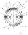
- a device according to the invention for adjusting the carbon brushes with an integrated changeover switch for such a reversible electric motor can be seen in more detail in FIG. 1 in a side view, the electric motor being shown only schematically.
- the device is designed as a flat component 1, which can be placed on the stator 4 of the electric motor in the axial direction 36.
- component 1 is used, for example, for fastening screwed, fixed with connector parts 13 or attached in a similar manner.
- the component 1 surrounds the collector 3 in a ring in the radial direction 37 on the rotor 2 of the electric motor.
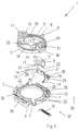
- the component 1 consists of a carrier 5 and a contact plate 6, as can be seen in particular in FIG. 4, in which the component 1 is shown in an exploded perspective view.
- the carrier 5 and the contact plate 6 can be assembled into component 1 by means of snap hooks 7 or other guide hooks projecting from the contact plate 6 in the axial direction 36.
- the snap hooks 7 can also be reversed on the carrier 5.
- the carrier 5 can be pivoted on the contact plate 6 by means of a handle 8, while the contact plate 6 is fixed in place on the stator 4 of the electric motor, as can be seen from FIG. 1.
- the carrier 5 and the contact plate 6 are made of plastic and are produced, for example, by injection molding.
- the chambers 10 each hold a brush holder 9, only one brush holder 9 being shown in FIG. 4.
- a molded hook on the chamber 10 engages by means of a pin 38 in a recess 12 on the brush holder 9 for fastening it in the chamber 10.
- the carbon brush 34 is in turn arranged, which rubs under spring pressure on the collector 3 of the electric motor when the component 1 is on Electric motor is mounted. Since the chamber 10 is open in the radial direction 37, there is thus the possibility of changing the brush holder 9 together with the carbon brush 34 in the installed state of the component 1 on the electric motor, without further disassembly of the component 1 being necessary.
- a pivoting of the carrier 5 by means of the handle 8 consequently leads to a pivoting of the carbon brushes 34 on the collector 3, as can be seen, for example, from FIG. 1.
- the contact system for this switch is located in component 1.
- the contact system consists of fixed contacts and switch contacts, the fixed contacts with the field windings on the stator 4 and the switch contacts with the carbon brushes 34 in the brush holder 9 being in electrical connection.
- the fixed contacts interact with the switching contacts as counter contacts in an alternate contacting of the carbon brushes 34 to reverse the direction of rotation of the electric motor when the carrier 5 is pivoted on the contact plate 6.
- the fixed contacts consist of two contact strips 19, only one of which is shown in FIG. 4.
- the contact strip 19 has, as contact surfaces 14 of the fixed contacts, end sections which are elastic in the radial direction 37, so that two contact surfaces 14 are located on each contact strip 19.
- In the contact plate 6 there is a groove 20 on the side facing the carrier 5, in which the two contact strips 19 are arranged opposite one another.
- On each contact strip 19, a line web 21 extends approximately centrally between the two contact surfaces 14.
- the land bridge 21 serves for the electrical connection of the contact strip 19 to the respective connection 16 for the field winding on the stator 4 of the electric motor.
- the contact strip 19, the line bridge 21 and the connection 16 for the field winding can be designed as a one-piece, metallic stamped part.
- the brush holder 9 located in the chamber 10 is arranged on the carrier 5 such that a surface 17 of the brush holder 9 faces the contact plate 6. A part 15 protrudes from this surface 17.
- This protruding part 15 projects into the area of the fixed contacts located in the groove 20 of the contact plate 6 and serves as a switching contact for direct contacting with the contact surfaces 14 on the contact strips 19.
- the protruding part 15 located on the brush holder 9 is preferably approximately perpendicular to the surface 17 and thus extends essentially in the axial direction 36.
- the contact strips 19 are in turn arranged approximately parallel to the protruding part 15 and thus also essentially in the axial direction 36 in the groove 20, the contact surfaces 14 on the contact strip 19 having an elasticity approximately in the radial direction Own direction 37.
- the switch contacts thus interact with the fixed contacts essentially in the radial direction 37 for making contact. This advantageously gives reliable contact, even with vibrations and Like., Which can occur in particular when used in power tools.
- the chamber 10 is particularly preferably designed to be open in the axial direction 36 on the side facing the contact plate 6.
- the surface 17 then represents a free surface 17 with respect to the carrier 5, which faces the contact plate 6.
- the brush holder 9 is made of metal, for example copper, so that the free surface 17 consists of electrically conductive material.
- the part 15 can, for example, be cut free from the free surface 17 and bent in one piece from the free surface 17, as can be seen in particular from FIG. 5.
- the electrical connection between the projecting part 15, which acts as a switching contact, and the carbon brush 34 is established via the surface 17.
- the switching positions of the component 1 used to switch the direction of rotation of the electric motor which can be adjusted when the support 5 is pivoted on the contact plate 6 by the interaction of the protruding parts 15 on the two brush holders 9 as switching contacts and the respective contact surfaces 14 of the two contact strips 19 as fixed contacts are shown in more detail in FIG. 6.
- the pair of brush holders 9 with the reference numerals 9a, 9b, the protruding parts 15 with the reference numerals 15a, 15b and the contact strips 19 with the reference numerals 19a, 19b are designated in more detail.
- the paired contact surfaces 14 are designated in greater detail on the contact strip 19a with the reference symbols 14a, 14c and on the contact strip 19b with 14b, 14d.
- the brush holder 9a contacts the contact surface 14b on the contact strip 19b by means of the part 15a and the brush holder 9b contacts the contact surface 14c on the contact strip 19a by means of the part 15b.
- the handle 8 in FIG. 6 is pivoted to the right according to the arrow 41, so that the brush holder 9a contacts the contact surface 14a on the contact strip 19a and the brush holder 9b contacts the contact surface 14d on the contact strip 19b.
- the contact strips 19a, 19b are thus alternately contacted by the brush holders 9a, 9b in the two switching positions, so that the polarity of the brush holders 9a, 9b is reversed in relation to the connections 16.
- the latching positions are determined in the present case by the interaction of a latching curve 22, which is located in the contact plate 6, with a latching spring 23, which is connected to the carrier 5.
- the detent spring 23 is preferably an axially Elastic element in the direction 36 on the surface 17 of the brush holder 9.
- the locking spring 23 can expediently be formed in one piece with the surface 17, as can be seen in particular in FIG. 5.
- the contact system consisting of the contact surfaces 14 and the protruding parts 15 is largely encapsulated by the component 1.
- a shoulder-shaped edge 18 on the carrier 5 covers the contact system upwards in the view according to FIG. 4.
- the contact system located in the groove 20 is further covered by the contact plate 6 downwards and laterally. This provides good protection against the effects of dust or the like in the electric hand tool.
- connection 16 for the field winding of the stator 4 is advantageously arranged in a receptacle 35 on the contact plate 6.
- the receptacle 35 can be designed such that the connection 16 is exposed on the side of the contact plate 6 facing away from the carrier 5.
- the connections 16 and the counter connections on the field windings can be designed in the most varied of forms, for example as plug connections, wire connections, sleeve connections or the like. Due to the simplification of the assembly, it is particularly preferred to design the connections 16 in the manner of plug-in cutting terminals 24.
- the line web 21 can also be designed such that it is possible to make contact with a radio interference suppression choke 25 for the electric motor, as is shown schematically in the illustration in FIG. 3.
- a receptacle 26 is arranged for the radio interference suppression choke 25 on the side of the contact plate 6 facing away from the carrier 5. With this receptacle 26 a clasp 27 located on the contact plate 6 interacts to hold the radio interference suppressor 25. This enables a holder that is independent of the diameter of the radio interference suppression choke 25.
- clamp contacts 28 which are in electrical connection with the connections 16 via the line web 21 for plugging in the radio interference suppressor 25.
- component 1 can optionally be equipped with or without radio interference suppression choke 25. If the radio interference suppression choke 25 is inserted, the bridging connection on the line web 21 is broken, since the electrical connection to the connections 16 is then established via the radio interference suppression choke 25.
- component 1 is manufactured separately and is only attached to the electric motor by the manufacturer of the power tool.
- a holding element that can be removed subsequently is arranged in the region of the chambers 10. At the same time this holding element serves as an aid for the assembly of the Component 1 on the electric motor, since the carbon brushes 34 cannot collide with parts of the electric motor when the component 1 is placed on it.
- the holding element consists of webs 31 arranged in a star shape, which are molded onto the carrier 5. Between the webs 31, holding surfaces 32 are fastened in the region of the brush holder 9 located in the chambers 10, so that the carbon brushes 34 are retained in the brush holder 9. After assembly of the component 1 on the electric motor, the webs 31 are broken off and removed from the carrier 5 at the injection points 33, so that the carbon brushes 34 contact the collector 3 of the electric motor due to the spring pressure of the compression spring 39 acting on them.
- the webs 31 can be broken off together with the carbon brushes 34 into the chambers 10 at the injection points 33 already after the brush holders 9 have been inserted, since in this case the webs 31 still bear against the carrier 5 for securing transport. Then the webs 31 with the holding surfaces 32 are automatically pushed out of the carrier 5 during the assembly of the component 1 on the electric motor.
- the holding element consists of individual holding tabs 29 located on the chamber 10, which retain the carbon brush 34 in the brush holder 9 by means of a pin 30. After assembly, the retaining tabs 29 are broken off, so that the carbon brushes 34 under the Action of a compression spring 39 or the like. Step out of the brush holder 9 and lie on the collector 3 of the electric motor.
- the invention is not restricted to the exemplary embodiments described and illustrated. Rather, it also includes all professional training within the scope of the inventive concept.
- the device according to the invention for adjusting the carbon brushes can be used not only in power tools but also in other devices with electric motors, for example in kitchen work tools or the like.
Landscapes
- Engineering & Computer Science (AREA)
- Power Engineering (AREA)
- Motor Or Generator Current Collectors (AREA)
- Motor Or Generator Frames (AREA)
Applications Claiming Priority (2)
| Application Number | Priority Date | Filing Date | Title |
|---|---|---|---|
| DE19545651A DE19545651A1 (de) | 1995-12-07 | 1995-12-07 | Verstellvorrichtung für die Kohlebürsten an einem Elektromotor |
| DE19545651 | 1995-12-07 |
Publications (3)
| Publication Number | Publication Date |
|---|---|
| EP0778655A2 true EP0778655A2 (fr) | 1997-06-11 |
| EP0778655A3 EP0778655A3 (fr) | 1998-04-01 |
| EP0778655B1 EP0778655B1 (fr) | 2001-06-27 |
Family
ID=7779441
Family Applications (1)
| Application Number | Title | Priority Date | Filing Date |
|---|---|---|---|
| EP96118969A Expired - Lifetime EP0778655B1 (fr) | 1995-12-07 | 1996-11-27 | Dispositif pour déplacer les balais de charbon dans un moteur électrique |
Country Status (3)
| Country | Link |
|---|---|
| US (1) | US5753993A (fr) |
| EP (1) | EP0778655B1 (fr) |
| DE (2) | DE19545651A1 (fr) |
Cited By (8)
| Publication number | Priority date | Publication date | Assignee | Title |
|---|---|---|---|---|
| EP0924842A3 (fr) * | 1997-12-19 | 2000-03-22 | Black & Decker Inc. | Inverseur de marche pour un moteur électrique |
| EP1515414A3 (fr) * | 2003-09-15 | 2007-07-04 | Shop Vac Corporation | Moteur électrique |
| EP1843452A1 (fr) * | 2006-04-06 | 2007-10-10 | HILTI Aktiengesellschaft | Dispositif de porte-balai |
| DE102010005333A1 (de) | 2009-01-24 | 2010-07-29 | Marquardt Gmbh | Verstelleinrichtung für einen Elektromotor |
| WO2010083814A2 (fr) | 2009-01-24 | 2010-07-29 | Marquardt Gmbh | Dispositif de réglage pour un moteur électrique |
| DE102010005332A1 (de) | 2009-01-24 | 2010-07-29 | Marquardt Gmbh | Verstelleinrichtung für einen Elektromotor |
| CN107834923A (zh) * | 2017-10-26 | 2018-03-23 | 夏丰收 | 一种转动调节的碳刷臂可调式自耦调压器 |
| CN112953130A (zh) * | 2021-03-11 | 2021-06-11 | 中国计量大学 | 一种直流电机碳刷安装装置 |
Families Citing this family (17)
| Publication number | Priority date | Publication date | Assignee | Title |
|---|---|---|---|---|
| DE19654352A1 (de) * | 1996-12-24 | 1998-06-25 | Bosch Gmbh Robert | Kollektormaschine mit Gehäusekontaktierung |
| JPH1158264A (ja) * | 1997-08-25 | 1999-03-02 | Makita Corp | 電動工具の漏電防止構造 |
| DE19909854A1 (de) * | 1998-03-11 | 1999-09-16 | Marquardt Gmbh | Elektrischer Schalter |
| JP2000116072A (ja) * | 1998-10-01 | 2000-04-21 | Makita Corp | ブラシホルダの取付構造 |
| US6759822B2 (en) * | 2001-12-20 | 2004-07-06 | Southern Illinois University | Methods and apparatus to improve the performance of universal electric motors |
| DE102004036805A1 (de) * | 2004-07-29 | 2006-03-23 | Robert Bosch Gmbh | Elektrowerkzeug mit innerem Befestigungselement |
| DE102004041486A1 (de) * | 2004-08-27 | 2006-03-02 | Robert Bosch Gmbh | Bürstenhalter mit Federelementen |
| DE102004041485A1 (de) * | 2004-08-27 | 2006-03-02 | Robert Bosch Gmbh | Bürstenhalter für eine elektrische Maschine |
| DE102004041488A1 (de) * | 2004-08-27 | 2006-03-02 | Robert Bosch Gmbh | Bürstenhalter und Bürstenköcher mit unterschiedlichen Abmessungen |
| DE102005000084A1 (de) | 2005-07-04 | 2007-01-18 | Hilti Ag | Verstellvorrichtung zur Drehrichtungsumkehr |
| CN102594035B (zh) * | 2011-01-07 | 2017-05-10 | 德昌电机(深圳)有限公司 | 电机 |
| DE102011005593A1 (de) * | 2011-03-16 | 2012-09-20 | Hilti Aktiengesellschaft | Handwerkzeugmaschine |
| CN103326498A (zh) * | 2012-03-20 | 2013-09-25 | 博世汽车部件(长沙)有限公司 | 电刷支架支撑装置及电动机 |
| DE102012014453A1 (de) * | 2012-07-21 | 2014-01-23 | Audi Ag | Elektrische Maschine und Kraftfahrzeug mit einer derartigen elektrischen Maschine |
| CN103944028A (zh) * | 2014-05-07 | 2014-07-23 | 上海东洋炭素工业有限公司 | 一种旋转碳刷架 |
| CN104410215B (zh) * | 2014-11-05 | 2017-01-11 | 西安航天精密机电研究所 | 一种有刷电机电刷压力调整方法及辅助工装 |
| CN115173616B (zh) * | 2022-08-15 | 2026-04-17 | 宝武集团鄂城钢铁有限公司 | 发电机碳刷支架和发电机 |
Family Cites Families (13)
| Publication number | Priority date | Publication date | Assignee | Title |
|---|---|---|---|---|
| GB642006A (en) * | 1947-04-26 | 1950-08-23 | Ingersoll Rand Co | Improvements in reversing mechanism for electric motors |
| US3440465A (en) * | 1965-10-01 | 1969-04-22 | Millers Falls Co | Reversing mechanism for electric motors |
| US4587384A (en) * | 1984-07-12 | 1986-05-06 | Black & Decker, Inc. | Sub-assembly for electric motor including reversing switch |
| DE3524614A1 (de) * | 1985-07-10 | 1987-01-15 | Bosch Gmbh Robert | Handwerkzeugmaschine fuer rechts- und linkslauf |
| JPS62118793A (ja) * | 1985-11-14 | 1987-05-30 | Matsushita Electric Ind Co Ltd | 整流子電動機 |
| US4694214A (en) * | 1986-03-07 | 1987-09-15 | United Technologies Electro Systems, Inc. | Brush holder for dynamoelectric machines |
| DE3731079A1 (de) * | 1987-09-16 | 1989-03-30 | Metabowerke Kg | Elektrohandwerkzeug mit einem universalmotor mit rechts- und linkslauf |
| NL8800366A (nl) * | 1988-02-15 | 1989-09-01 | Emerson Electric Co | Montage-inrichting voor borstels bij een omkeerbare collectormotor. |
| DE3834609A1 (de) * | 1988-10-11 | 1990-04-12 | Schunk Motorensysteme | Elektromotor |
| DE8908646U1 (de) * | 1989-07-15 | 1989-10-05 | Kress-elektrik GmbH & Co, Elektromotorenfabrik, 7457 Bisingen | Elektrischer Universalmotor |
| DE3943651C2 (fr) * | 1989-07-15 | 1993-01-28 | Kress-Elektrik Gmbh & Co. Elektromotorenfabrik, 7457 Bisingen, De | |
| DE3923421A1 (de) * | 1989-07-15 | 1991-01-24 | Kress Elektrik Gmbh & Co | Elektrischer universalmotor |
| DE4004464A1 (de) * | 1989-07-15 | 1991-01-24 | Kress Elektrik Gmbh & Co | Elektrowerkzeug |
-
1995
- 1995-12-07 DE DE19545651A patent/DE19545651A1/de not_active Withdrawn
-
1996
- 1996-11-27 EP EP96118969A patent/EP0778655B1/fr not_active Expired - Lifetime
- 1996-11-27 DE DE59607166T patent/DE59607166D1/de not_active Expired - Lifetime
- 1996-12-03 US US08/758,940 patent/US5753993A/en not_active Expired - Lifetime
Cited By (13)
| Publication number | Priority date | Publication date | Assignee | Title |
|---|---|---|---|---|
| EP0924842A3 (fr) * | 1997-12-19 | 2000-03-22 | Black & Decker Inc. | Inverseur de marche pour un moteur électrique |
| EP1583207A3 (fr) * | 1997-12-19 | 2005-11-23 | BLACK & DECKER INC. | Inverseur de marche pour un moteur électrique |
| EP1515414A3 (fr) * | 2003-09-15 | 2007-07-04 | Shop Vac Corporation | Moteur électrique |
| US8141231B2 (en) | 2003-09-15 | 2012-03-27 | Shop Vac | Electric motor |
| EP1843452A1 (fr) * | 2006-04-06 | 2007-10-10 | HILTI Aktiengesellschaft | Dispositif de porte-balai |
| DE102010005332A1 (de) | 2009-01-24 | 2010-07-29 | Marquardt Gmbh | Verstelleinrichtung für einen Elektromotor |
| WO2010083814A2 (fr) | 2009-01-24 | 2010-07-29 | Marquardt Gmbh | Dispositif de réglage pour un moteur électrique |
| DE102010005333A1 (de) | 2009-01-24 | 2010-07-29 | Marquardt Gmbh | Verstelleinrichtung für einen Elektromotor |
| US9071119B2 (en) | 2009-01-24 | 2015-06-30 | Marquardt Gmbh | Adjusting device for an electric motor |
| US10033256B2 (en) | 2009-01-24 | 2018-07-24 | Marquardt Gmbh | Adjusting device for an electric motor |
| CN107834923A (zh) * | 2017-10-26 | 2018-03-23 | 夏丰收 | 一种转动调节的碳刷臂可调式自耦调压器 |
| CN112953130A (zh) * | 2021-03-11 | 2021-06-11 | 中国计量大学 | 一种直流电机碳刷安装装置 |
| CN112953130B (zh) * | 2021-03-11 | 2023-09-15 | 中国计量大学 | 一种直流电机碳刷安装装置 |
Also Published As
| Publication number | Publication date |
|---|---|
| EP0778655A3 (fr) | 1998-04-01 |
| DE59607166D1 (de) | 2001-08-02 |
| US5753993A (en) | 1998-05-19 |
| DE19545651A1 (de) | 1997-06-12 |
| EP0778655B1 (fr) | 2001-06-27 |
Similar Documents
| Publication | Publication Date | Title |
|---|---|---|
| EP0778655A2 (fr) | Dispositif pour déplacer les balais de charbon dans un moteur électrique | |
| DE3629634C2 (fr) | ||
| DE3912873C2 (fr) | ||
| DE69216784T2 (de) | Kleinmotor mit einer installierten Erdklemme | |
| DE3404973C2 (fr) | ||
| DE19938068A1 (de) | Leistungsverteilungszentrum mit verbesserter Leistungsversorgungsverbindung | |
| DE19938342A1 (de) | Bürstensystem für elektrische Motoren | |
| DE69002535T2 (de) | Bürstenhalter für einen Elektromotor. | |
| EP0225978A2 (fr) | Dispositif à balais pour moteurs électriques | |
| DE69301191T2 (de) | Zusammengesetzter Kommutator | |
| DE69519410T2 (de) | Lampenfassung und Verfahren zu deren Zusammenbau | |
| DE19902433C1 (de) | Kommutatormotor | |
| EP0224054B1 (fr) | Moteur électrique pour un petit outil électrique | |
| DE2458991A1 (de) | Buerstenanordnung fuer einen miniaturmotor | |
| DE102004039611B4 (de) | Elektrisch betriebenes Werkzeuggerät | |
| EP0655173B1 (fr) | Dispositif pour relier un moteur a au moins deux pistes conductrices | |
| DE3614970A1 (de) | Anordnung zur herstellung von elektrischen verbindungen in einem elektromotor | |
| EP0892997B1 (fr) | Connecteur a fiches pour cables | |
| DE3314412A1 (de) | Kleine kollektormaschine, insbesondere motor | |
| DE3538941A1 (de) | Feldstecker fuer einen elektromotor | |
| WO2006117265A1 (fr) | Dispositif de raccord | |
| EP1763109A1 (fr) | Support d'agraffe de contact pour le montage sur une barre électrique et dispositif du support sur celle-ci | |
| EP2654183A1 (fr) | Dispositif de commutation pour un moteur électrique | |
| DE2757451A1 (de) | Elektrischer schalter | |
| EP1987580B1 (fr) | Unite d'entrainement antiparasitee, notamment pour entrainer une soufflerie de vehicule automobile |
Legal Events
| Date | Code | Title | Description |
|---|---|---|---|
| PUAI | Public reference made under article 153(3) epc to a published international application that has entered the european phase |
Free format text: ORIGINAL CODE: 0009012 |
|
| AK | Designated contracting states |
Kind code of ref document: A2 Designated state(s): CH DE ES GB LI NL |
|
| PUAL | Search report despatched |
Free format text: ORIGINAL CODE: 0009013 |
|
| AK | Designated contracting states |
Kind code of ref document: A3 Designated state(s): CH DE ES GB LI NL |
|
| 17P | Request for examination filed |
Effective date: 19980729 |
|
| 17Q | First examination report despatched |
Effective date: 19990429 |
|
| GRAG | Despatch of communication of intention to grant |
Free format text: ORIGINAL CODE: EPIDOS AGRA |
|
| GRAG | Despatch of communication of intention to grant |
Free format text: ORIGINAL CODE: EPIDOS AGRA |
|
| GRAG | Despatch of communication of intention to grant |
Free format text: ORIGINAL CODE: EPIDOS AGRA |
|
| GRAH | Despatch of communication of intention to grant a patent |
Free format text: ORIGINAL CODE: EPIDOS IGRA |
|
| GRAH | Despatch of communication of intention to grant a patent |
Free format text: ORIGINAL CODE: EPIDOS IGRA |
|
| GRAA | (expected) grant |
Free format text: ORIGINAL CODE: 0009210 |
|
| AK | Designated contracting states |
Kind code of ref document: B1 Designated state(s): CH DE ES GB LI NL |
|
| REG | Reference to a national code |
Ref country code: CH Ref legal event code: EP |
|
| GBT | Gb: translation of ep patent filed (gb section 77(6)(a)/1977) |
Effective date: 20010627 |
|
| REF | Corresponds to: |
Ref document number: 59607166 Country of ref document: DE Date of ref document: 20010802 |
|
| REG | Reference to a national code |
Ref country code: CH Ref legal event code: NV Representative=s name: KELLER & PARTNER PATENTANWAELTE AG |
|
| PG25 | Lapsed in a contracting state [announced via postgrant information from national office to epo] |
Ref country code: ES Free format text: LAPSE BECAUSE OF FAILURE TO SUBMIT A TRANSLATION OF THE DESCRIPTION OR TO PAY THE FEE WITHIN THE PRESCRIBED TIME-LIMIT Effective date: 20011220 |
|
| REG | Reference to a national code |
Ref country code: GB Ref legal event code: IF02 |
|
| PLBE | No opposition filed within time limit |
Free format text: ORIGINAL CODE: 0009261 |
|
| STAA | Information on the status of an ep patent application or granted ep patent |
Free format text: STATUS: NO OPPOSITION FILED WITHIN TIME LIMIT |
|
| 26N | No opposition filed | ||
| PGFP | Annual fee paid to national office [announced via postgrant information from national office to epo] |
Ref country code: CH Payment date: 20141119 Year of fee payment: 19 Ref country code: GB Payment date: 20141119 Year of fee payment: 19 |
|
| PGFP | Annual fee paid to national office [announced via postgrant information from national office to epo] |
Ref country code: NL Payment date: 20141119 Year of fee payment: 19 |
|
| REG | Reference to a national code |
Ref country code: CH Ref legal event code: PCAR Free format text: NEW ADDRESS: EIGERSTRASSE 2 POSTFACH, 3000 BERN 14 (CH) |
|
| PGFP | Annual fee paid to national office [announced via postgrant information from national office to epo] |
Ref country code: DE Payment date: 20151221 Year of fee payment: 20 |
|
| REG | Reference to a national code |
Ref country code: CH Ref legal event code: PL |
|
| GBPC | Gb: european patent ceased through non-payment of renewal fee |
Effective date: 20151127 |
|
| PG25 | Lapsed in a contracting state [announced via postgrant information from national office to epo] |
Ref country code: CH Free format text: LAPSE BECAUSE OF NON-PAYMENT OF DUE FEES Effective date: 20151130 Ref country code: LI Free format text: LAPSE BECAUSE OF NON-PAYMENT OF DUE FEES Effective date: 20151130 |
|
| REG | Reference to a national code |
Ref country code: NL Ref legal event code: MM Effective date: 20151201 |
|
| PG25 | Lapsed in a contracting state [announced via postgrant information from national office to epo] |
Ref country code: NL Free format text: LAPSE BECAUSE OF NON-PAYMENT OF DUE FEES Effective date: 20151201 |
|
| PG25 | Lapsed in a contracting state [announced via postgrant information from national office to epo] |
Ref country code: GB Free format text: LAPSE BECAUSE OF NON-PAYMENT OF DUE FEES Effective date: 20151127 |
|
| REG | Reference to a national code |
Ref country code: DE Ref legal event code: R071 Ref document number: 59607166 Country of ref document: DE |