EP0779020A1 - Gezogene Mähmaschine mit seitlicher Förderung - Google Patents
Gezogene Mähmaschine mit seitlicher Förderung Download PDFInfo
- Publication number
- EP0779020A1 EP0779020A1 EP96610049A EP96610049A EP0779020A1 EP 0779020 A1 EP0779020 A1 EP 0779020A1 EP 96610049 A EP96610049 A EP 96610049A EP 96610049 A EP96610049 A EP 96610049A EP 0779020 A1 EP0779020 A1 EP 0779020A1
- Authority
- EP
- European Patent Office
- Prior art keywords
- conveyor
- track
- crop
- windrower
- shield
- Prior art date
- Legal status (The legal status is an assumption and is not a legal conclusion. Google has not performed a legal analysis and makes no representation as to the accuracy of the status listed.)
- Ceased
Links
- 239000002689 soil Substances 0.000 claims abstract description 3
- 230000001360 synchronised effect Effects 0.000 claims description 3
- 238000006073 displacement reaction Methods 0.000 claims description 2
- 239000000463 material Substances 0.000 description 4
- 230000003750 conditioning effect Effects 0.000 description 1
- 230000001419 dependent effect Effects 0.000 description 1
- 230000000694 effects Effects 0.000 description 1
- 238000003306 harvesting Methods 0.000 description 1
- 230000010355 oscillation Effects 0.000 description 1
Images

Classifications
-
- A—HUMAN NECESSITIES
- A01—AGRICULTURE; FORESTRY; ANIMAL HUSBANDRY; HUNTING; TRAPPING; FISHING
- A01D—HARVESTING; MOWING
- A01D57/00—Delivering mechanisms for harvesters or mowers
- A01D57/20—Delivering mechanisms for harvesters or mowers with conveyor belts
Definitions
- the present invention relates to a towed mower of the type comprising a draw bar which is hinged near the longitudinal centre plane of the mower relative to the working direction for connection with a tractor, mowing means which are adapted during operation to mow a crop in a windrower track of a certain width, and a conveyor with a path of conveyance running transversely to the windrower track for alternatingly during operation to place the windrow from a windrower track at one side of the same windrower track and to place the windrow in the previously mowed windrower track near to or on top of a windrow already laid out.
- a mower of this type is known from US-A-4 590 751, which shows how it is possible with such a mower to harvest a field, the passes taking alternatingly place in one direction and the other, whereby the windrow during one field pass is placed within the windrower track at a distance from the crop not yet harvested, which distance is sufficient for leaving room for the wheels of one side of the tractor during the next field pass, and the windrow is during the subsequent pass laid out further at the same side of the mower as before to place the harvested crop from the second pass as close as possible to the windrow from the first pass.
- a lift-suspended mower which is provided with a transverse conveyor adapted to alternatingly run one way or the other, to alternatingly place the windrow at one side of the mower and at the other side thereof.
- a stationary shield is provided at each end of the conveyor for limiting the width of a laid out windrow.
- the object of the present invention is to solve the above problem existing in connection with the prior art. It should in this connection be noted that it would not be desirable to provide the mower according to US-A-4 590 750 with a stationary limiting shield, as it is the aim during a second field pass to place the windrow as far as possible to the side of the mower.
- a towed mower which is characteristic in comprising a shield and means for moving this shield between a position, in which it stops crop discharged from the conveyor, whereby the crop falls down onto the soil within the track of the mower, and a position, in which it is not in the way of the crop discharged from the conveyor.
- US-A-5 351 468 discloses a mower comprising a draw bar hinged to one side of the mower, a transverse conveyor and a movable shield at one end of the conveyor.
- the conveyor is driven alternatingly in one direction and the other, whereby the shield is correspondingly moved between a closed position, in which it leads material from the mower to the conveyor, and an open position, in which it is out of the way of material leaving the conveyor.
- the shield may possibly control the flow of material leaving the conveyor, but such an effect has not been mentioned in the publication and is not the object of the movement from a closed to an open position.
- the shield is moved from the closed position to the open position in order not to lead material from the conveyor back to the mower.
- the means for moving the shield are according to the invention connected with the conveyor or with means for its displacement, such that the movements of the shield and the conveyor are synchronized.
- This connection may for instance be established mechanically or hydraulically.
- the mower comprises double-acting hydraulic cylinders for swinging the draw bar, displacing the conveyor and moving the shield, respectively, and these hydraulic cylinders are connected in series.
- the hydraulic cylinders are connected with a double-acting hydraulic power take-off on a tractor the conveyor and the shield are moved correctly relative to the positioning of the mower behind the tractor, the positioning being controlled by means of the oscillation of the draw bar.
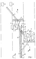
- the figures show a mower with a frame 1, mowing means in form of cutter discs 2 and a draw bar 3 which is hinged at 4 to the frame 1 near its centre. Moreover, the mower is provided with driving wheels 5 and a transverse conveyor 6, which in this case is a conveyor belt and is suspended in the frame 1 by means of two parallelogram arms 7, whereby the conveyor 6 may be displaced in its transport direction.
- a transverse conveyor 6 which in this case is a conveyor belt and is suspended in the frame 1 by means of two parallelogram arms 7, whereby the conveyor 6 may be displaced in its transport direction.
- the draw bar 4 is connected with a tractor, of which only the rear wheels 8 are shown, and the mower comprises further conditioning means and throwing means for leading harvested crop onto the conveyor 6.
- a stationary shield 9 is provided behind the conveyor to prevent crop which is conveyed on the conveyer from falling out over the backward facing side edge of the conveyor.
- a movable shield 10 is provided which is fastened to a pivotable arm 11, by means of which it may be moved between two positions shown in Figs. 2 and 3, respectively.
- double-acting hydraulic cylinders are provided for swinging the draw bar 3, the parallelogram arms 7 and the arm 11, respectively, in order to move the draw bar 3, the conveyor 6 and the movable shield 10 respectively, between the positions shown in the figures.
- double-acting hydraulic cylinders By connecting these hydraulic cylinders in series and with a double-acting hydraulic power take-off on the tractor, synchronous movements are achieved, such that the positions of the conveyor 6 and the shield 10 become dependent on the position of the draw bar 3.
- the mower works in the following way:
- the draw bar 3 and the conveyor 6 have been taken to the opposite side relative to the transport direction 12 of the conveyor 6.
- the shield 10 is in the position shown in Fig. 2 and ensures a certain distance a between the laid out windrow 13 and the crop not yet harvested. This distance a is sufficient for ensuring that the tractor during a subsequent pass may drive with its (in the embodiment left) wheel between the crop not harvested and the windrow 13 without driving in it.
Landscapes
- Life Sciences & Earth Sciences (AREA)
- Environmental Sciences (AREA)
- Harvester Elements (AREA)
Applications Claiming Priority (2)
| Application Number | Priority Date | Filing Date | Title |
|---|---|---|---|
| DK142395A DK173226B1 (da) | 1995-12-15 | 1995-12-15 | Bugseret slåmaskine med tværgående afgrødetransportør |
| DK1423/95 | 1995-12-15 |
Publications (1)
| Publication Number | Publication Date |
|---|---|
| EP0779020A1 true EP0779020A1 (de) | 1997-06-18 |
Family
ID=8104678
Family Applications (1)
| Application Number | Title | Priority Date | Filing Date |
|---|---|---|---|
| EP96610049A Ceased EP0779020A1 (de) | 1995-12-15 | 1996-12-12 | Gezogene Mähmaschine mit seitlicher Förderung |
Country Status (2)
| Country | Link |
|---|---|
| EP (1) | EP0779020A1 (de) |
| DK (1) | DK173226B1 (de) |
Cited By (8)
| Publication number | Priority date | Publication date | Assignee | Title |
|---|---|---|---|---|
| WO1999033332A1 (en) * | 1997-12-23 | 1999-07-08 | Kverneland Taarup A/S | Mower for cutting standing crop |
| EP0934690A1 (de) | 1998-02-04 | 1999-08-11 | Deere & Company | Schwadeinrichtung |
| DE19932285A1 (de) * | 1999-07-10 | 2001-04-26 | Deere & Co | Selbstfahrendes Mähfahrzeug und Förderer |
| EP1444880A1 (de) * | 2003-01-20 | 2004-08-11 | JF-Fabriken - J. Freudendahl A/S | Gezogene Mähmaschine |
| EP1779716A3 (de) * | 2005-10-26 | 2007-12-19 | Claas Saulgau Gmbh | Mähmaschine mit einem Mähwerk und einer Querfördervorrichtung |
| EP2529614A1 (de) * | 2011-05-31 | 2012-12-05 | FELLA-Werke GmbH | Mähwerkskombination |
| US20140196429A1 (en) * | 2013-01-17 | 2014-07-17 | Kuhn S.A. | Haymaking machine comprising an improved deflector |
| EP4374679A1 (de) * | 2022-08-26 | 2024-05-29 | Deere & Company | Erkennung der mittellinie einer schwadenbraue für mapping- und steuerungsbetrieb |
Citations (12)
| Publication number | Priority date | Publication date | Assignee | Title |
|---|---|---|---|---|
| FR1420072A (fr) * | 1964-01-23 | 1965-12-03 | Deere & Co | Andaineuse équipée de transporteurs à changement de positions et à renversement de marche |
| FR2483736A1 (fr) * | 1980-06-10 | 1981-12-11 | Ragot Robert | Faucheuse |
| GB2077562A (en) * | 1980-06-12 | 1981-12-23 | Taarup As Maskinfab | Harvesting machines |
| DE3329276A1 (de) | 1982-10-28 | 1984-05-03 | Bucher-Guyer AG Maschinenfabrik, 8166 Niederweningen, Zürich | Futtererntemaschine mit seitlicher foerderung |
| US4590750A (en) | 1984-05-04 | 1986-05-27 | Royer Ii Clady J | Saddle stirrup setting device |
| US4590751A (en) | 1984-06-20 | 1986-05-27 | Deere & Company | Double windrowing attachment for harvester |
| GB2194875A (en) * | 1986-09-11 | 1988-03-23 | Harry West | Harvesting equipment |
| EP0332552A1 (de) * | 1988-03-04 | 1989-09-13 | Kuhn S.A. | Verbesserung an Landmaschinen für die Futterernte |
| EP0558436A1 (de) * | 1992-02-28 | 1993-09-01 | Jf-Fabriken - J. Freudendahl A/S | Mäher zum Ernten von Gras |
| EP0579573A1 (de) * | 1992-07-16 | 1994-01-19 | Jf-Fabriken - J. Freudendahl A/S | An einer Kupplungsvorrichtung angehängte Mähmaschine |
| DE4407576A1 (de) * | 1993-03-08 | 1994-09-15 | Freudendahl J Fab As | Vorrichtung zum Mähen |
| US5351468A (en) * | 1993-03-31 | 1994-10-04 | Joel Pominville | Selectable windrowing mower attachment and method of mounting |
-
1995
- 1995-12-15 DK DK142395A patent/DK173226B1/da not_active IP Right Cessation
-
1996
- 1996-12-12 EP EP96610049A patent/EP0779020A1/de not_active Ceased
Patent Citations (12)
| Publication number | Priority date | Publication date | Assignee | Title |
|---|---|---|---|---|
| FR1420072A (fr) * | 1964-01-23 | 1965-12-03 | Deere & Co | Andaineuse équipée de transporteurs à changement de positions et à renversement de marche |
| FR2483736A1 (fr) * | 1980-06-10 | 1981-12-11 | Ragot Robert | Faucheuse |
| GB2077562A (en) * | 1980-06-12 | 1981-12-23 | Taarup As Maskinfab | Harvesting machines |
| DE3329276A1 (de) | 1982-10-28 | 1984-05-03 | Bucher-Guyer AG Maschinenfabrik, 8166 Niederweningen, Zürich | Futtererntemaschine mit seitlicher foerderung |
| US4590750A (en) | 1984-05-04 | 1986-05-27 | Royer Ii Clady J | Saddle stirrup setting device |
| US4590751A (en) | 1984-06-20 | 1986-05-27 | Deere & Company | Double windrowing attachment for harvester |
| GB2194875A (en) * | 1986-09-11 | 1988-03-23 | Harry West | Harvesting equipment |
| EP0332552A1 (de) * | 1988-03-04 | 1989-09-13 | Kuhn S.A. | Verbesserung an Landmaschinen für die Futterernte |
| EP0558436A1 (de) * | 1992-02-28 | 1993-09-01 | Jf-Fabriken - J. Freudendahl A/S | Mäher zum Ernten von Gras |
| EP0579573A1 (de) * | 1992-07-16 | 1994-01-19 | Jf-Fabriken - J. Freudendahl A/S | An einer Kupplungsvorrichtung angehängte Mähmaschine |
| DE4407576A1 (de) * | 1993-03-08 | 1994-09-15 | Freudendahl J Fab As | Vorrichtung zum Mähen |
| US5351468A (en) * | 1993-03-31 | 1994-10-04 | Joel Pominville | Selectable windrowing mower attachment and method of mounting |
Cited By (10)
| Publication number | Priority date | Publication date | Assignee | Title |
|---|---|---|---|---|
| WO1999033332A1 (en) * | 1997-12-23 | 1999-07-08 | Kverneland Taarup A/S | Mower for cutting standing crop |
| EP0934690A1 (de) | 1998-02-04 | 1999-08-11 | Deere & Company | Schwadeinrichtung |
| US6145289A (en) * | 1998-02-04 | 2000-11-14 | Deere & Company | Windrow grouper arrangement |
| DE19932285A1 (de) * | 1999-07-10 | 2001-04-26 | Deere & Co | Selbstfahrendes Mähfahrzeug und Förderer |
| EP1444880A1 (de) * | 2003-01-20 | 2004-08-11 | JF-Fabriken - J. Freudendahl A/S | Gezogene Mähmaschine |
| EP1779716A3 (de) * | 2005-10-26 | 2007-12-19 | Claas Saulgau Gmbh | Mähmaschine mit einem Mähwerk und einer Querfördervorrichtung |
| EP2529614A1 (de) * | 2011-05-31 | 2012-12-05 | FELLA-Werke GmbH | Mähwerkskombination |
| US20140196429A1 (en) * | 2013-01-17 | 2014-07-17 | Kuhn S.A. | Haymaking machine comprising an improved deflector |
| EP4374679A1 (de) * | 2022-08-26 | 2024-05-29 | Deere & Company | Erkennung der mittellinie einer schwadenbraue für mapping- und steuerungsbetrieb |
| US12514155B2 (en) | 2022-08-26 | 2026-01-06 | Deere & Company | Windrow center line detection for mapping and controlling operation |
Also Published As
| Publication number | Publication date |
|---|---|
| DK142395A (da) | 1997-06-16 |
| DK173226B1 (da) | 2000-04-17 |
Similar Documents
| Publication | Publication Date | Title |
|---|---|---|
| US4392339A (en) | Crop windrowing machine having double windrow-forming attachment | |
| US4910951A (en) | Windrow merger | |
| US4171606A (en) | Attitude control for a harvester pickup | |
| US4938010A (en) | Harvesting header having adjustable width, draper belt discharge opening | |
| US3841070A (en) | Windrow placement device and harvesting method | |
| US20080283364A1 (en) | Extendable conveyor system | |
| US6862873B2 (en) | Windrow merging attachment | |
| CA2313579C (en) | Self-propelled mowing vehicle and conveyor | |
| US3911649A (en) | Windrow placement device and harvesting method | |
| EP0865235B1 (de) | Verfahren und maschinekombination,rechen und aufnehmer und versetzungselement | |
| US3695015A (en) | Deflector arrangement for single or double window laying, convertible table for swathers | |
| EP0779020A1 (de) | Gezogene Mähmaschine mit seitlicher Förderung | |
| US5980382A (en) | Self-propelled peanut combine | |
| EP0558437B1 (de) | Mähmaschine für Gewächs | |
| US7877974B2 (en) | Floating swathgate | |
| EP1796454B2 (de) | Erntegerät, insbesondere erntevorsatz für landwirtschaftliche erntemaschinen zum aufnehmen und weiterfördern von halmfrüchten | |
| GB2077562A (en) | Harvesting machines | |
| US3252520A (en) | Tomato harvester | |
| EP0439991A1 (de) | Querförder für Schwader | |
| US4022005A (en) | Double windrowing method and apparatus | |
| US7610741B2 (en) | Mower with foldable mowing units | |
| EP0558436B1 (de) | Mäher zum Ernten von Gras | |
| US10822172B1 (en) | Merger extension chute and conveyor | |
| US3928955A (en) | Double windrowing method and apparatus | |
| JP3405315B2 (ja) | コンバインの刈取装置 |
Legal Events
| Date | Code | Title | Description |
|---|---|---|---|
| PUAI | Public reference made under article 153(3) epc to a published international application that has entered the european phase |
Free format text: ORIGINAL CODE: 0009012 |
|
| AK | Designated contracting states |
Kind code of ref document: A1 Designated state(s): DE FR GB SE |
|
| 17P | Request for examination filed |
Effective date: 19971201 |
|
| 17Q | First examination report despatched |
Effective date: 19990920 |
|
| GRAG | Despatch of communication of intention to grant |
Free format text: ORIGINAL CODE: EPIDOS AGRA |
|
| STAA | Information on the status of an ep patent application or granted ep patent |
Free format text: STATUS: THE APPLICATION HAS BEEN REFUSED |
|
| 18R | Application refused |
Effective date: 20011231 |