EP0779103B1 - Vorrichtung zur visuellen Untersuchung einer Flüssigkeit durch Vermengen mit einem flüssigen Reagens - Google Patents
Vorrichtung zur visuellen Untersuchung einer Flüssigkeit durch Vermengen mit einem flüssigen Reagens Download PDFInfo
- Publication number
- EP0779103B1 EP0779103B1 EP96420352A EP96420352A EP0779103B1 EP 0779103 B1 EP0779103 B1 EP 0779103B1 EP 96420352 A EP96420352 A EP 96420352A EP 96420352 A EP96420352 A EP 96420352A EP 0779103 B1 EP0779103 B1 EP 0779103B1
- Authority
- EP
- European Patent Office
- Prior art keywords
- alveoles
- test
- module
- cells
- blood
- Prior art date
- Legal status (The legal status is an assumption and is not a legal conclusion. Google has not performed a legal analysis and makes no representation as to the accuracy of the status listed.)
- Expired - Lifetime
Links
Images


Classifications
-
- B—PERFORMING OPERATIONS; TRANSPORTING
- B01—PHYSICAL OR CHEMICAL PROCESSES OR APPARATUS IN GENERAL
- B01L—CHEMICAL OR PHYSICAL LABORATORY APPARATUS FOR GENERAL USE
- B01L3/00—Containers or dishes for laboratory use, e.g. laboratory glassware; Droppers
- B01L3/50—Containers for the purpose of retaining a material to be analysed, e.g. test tubes
- B01L3/502—Containers for the purpose of retaining a material to be analysed, e.g. test tubes with fluid transport, e.g. in multi-compartment structures
- B01L3/5025—Containers for the purpose of retaining a material to be analysed, e.g. test tubes with fluid transport, e.g. in multi-compartment structures for parallel transport of multiple samples
-
- G—PHYSICS
- G01—MEASURING; TESTING
- G01N—INVESTIGATING OR ANALYSING MATERIALS BY DETERMINING THEIR CHEMICAL OR PHYSICAL PROPERTIES
- G01N33/00—Investigating or analysing materials by specific methods not covered by groups G01N1/00 - G01N31/00
- G01N33/48—Biological material, e.g. blood, urine; Haemocytometers
- G01N33/50—Chemical analysis of biological material, e.g. blood, urine; Testing involving biospecific ligand binding methods; Immunological testing
- G01N33/80—Chemical analysis of biological material, e.g. blood, urine; Testing involving biospecific ligand binding methods; Immunological testing involving blood groups or blood types or red blood cells
Definitions
- the invention relates to a visual control device. of a liquid by mixing with a reactive liquid.
- This device applies to pre-transfusion control test blood group, for example, but not exclusively.
- pre-transfusion control which is delivered includes among other things a hose small diameter, which will be called hereinafter “witness noodle” containing the same blood as the one in the pocket and which is marked at regular intervals with a number identical identification to that printed on the pocket; the nurses who took the sample crush and close the tube by welding between hot electrodes at regular intervals in the areas separating those bearing the identification number; they constitute thus small blood tanks bearing a number Identification.
- the card also includes, in particular, information concerning the person who carried out the inspection pre-transfusion and it is archived in the file of the patient.
- This card has the disadvantage of not eliminate the risk of pollution of a test serum by the other, nor the risk of inversion of the test sera; in particular the bottle test serum may be degraded if it has been out of a refrigerator for too long or have been polluted at the time of collection of the drop in a previous operation.
- Another card contains dehydrated test sera previously placed in the boxes to eliminate the risk of reversal, but the risk of pollution remains at the time of their rehydration.
- the object of the invention is to propose a method operating room as well as an ambulatory device to make pre-transfusion checks more reliable whatever the conditions of implementation and also allow a posteriori control of the results the pre-transfusion check carried out.
- patent EP-A-0054087 there is also known a device comprising flanges provided with teeth having alveoli piercers linked by a mechanical connection.
- the device according to the invention avoids plugging pollution by mechanically combining each plug in each cell without inversions clogging are possible.
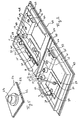
- Figure 1 shows in perspective view a ambulatory test device according to the invention comprising two pre-transfusion control modules according to the invention one of which was cut out to show the structure.
- Figure 2 shows in perspective view a ambulatory test device according to a preferred version of the invention comprising four control modules pre-transfusion in open or closed position including one of the modules is partially cut out to show the structure.
- Figure 3 shows a section of the device according to Figure 1 in the closed position with the control noodle in its storage slot.
- FIG. 4 represents a perspective view of the device of Figure 2 when folded on itself to form a pocket.
- Figure 5 shows a perspective view of a cell according to a preferred version of the invention.
- Figure 6 shows a vertical section of a cell formed by an independent closed and clipped container on a support. The filling device is not represented.
- Figure 7 shows a perspective view partially exploded from two cells communicating by channels with housings each containing a container of reactive liquid.
- the capping and filling device alveoli is not shown.
- the method consists in carrying out the intake test and mixing of a liquid to be controlled in cavities of a device each containing a liquid reagent which was introduced at the time of its factory packaging and the result of which is observed visually directly in each cavity at the level of physical characteristics such as consistency and / or color without this list is exhaustive; the cavity is then closed hermetically to keep the result obtained by the mixture thus produced.
- Reactive liquid is introduced in necessary and sufficient quantity in a cell, in which it is enclosed and stored; there is as much of cells that there are different reactive liquids necessary to carry out the test and all of these alveoli constitute a test module; you need a module test by liquid to be tested.
- This process can be applied to the realization of the pre-transfusion test in which the liquid to be tested is blood and the reagent fluids of the Anti-A test serum and Anti-B test serum; we mix the recipient's blood in each cavity of a module of two cells which have been previously opened and then we observe the result which results either in agglutination or by the absence of agglutination and the alveoli are closed; then the donor's blood is mixed from a witness noodle taken from the pocket; in each of cavities of another module of two cells which have been previously opened and then which will then be closed after visual observation of the result.
- the risk of pollution of one test serum by the other is eliminated and the risk of pollution of one blood by the other is eliminated.
- the test device contains at least two modules 1 and 2 (fig. 1) of at least two closed cells 3 and 4 containing respectively Anti-A test serum and test serum Anti-B; each module 1 and 2 of cells 3 and 4 further includes a storage device 5 and 6, after use of the corresponding control noodle 7 having used for the test in the corresponding cell module 3 and 4; this storage device is designed to prevent the control noodle is inadvertently lost and cannot be recovered only by a voluntary act.
- Control pre-transfusion consists of opening a first module 1 of two cells 3 and 4 to introduce a drop therein recipient's blood; then.
- the cells 3 and 4 are preferably made in injected thermoplastics (fig. 1) or thermoformed (fig. 2) and generally occur arranged in groups of two on a flat plate 8 (fig. 1) the opening 9 of the cells 3 and 4 can also be located well at the level of the plate 8 with the cells 3 and 4 embedded in the latter or on the contrary the cells 11 and 12 (fig. 2) of module 10 form a wart on the main plate 26; choices are made taking account of the technical solutions selected for the various plugging functions of cells 3 and 4 or 11 and 12 and storage with noodle tamper of blood 7 used for the pre-transfusion test.
- the cells 3 and 4 are closed after introduction of blood, to keep track of the result the pre-transfusion check carried out; in a version preferred of the invention, it is the same device for manual closure 14 (fig. 5) used to seal the cells 11 and 12 after introduction of the test sera and after carrying out pre-transfusion testing; it is designed so that there is an associated closure device 14 to each group of cells 11 and 12 without there being possibility of interchanging the plugs 15 to constitute a module 10.
- a closure device possibly inviolable and non-reusable, easy to install industrially after introduction of test sera in the alveoli groups, combined with another manual closure system after pre-transfusion control; as an example no limitative, cells 3 and 4 (fig. 1) can be closed after filling with test serum with a film 16 (fig. 1) welded and which can be removed by peeling; plugs 17 fixed to each group of cells 3 and 4 corresponding by a flexible mechanical connection 18 allow to close the cells 19 (fig. 3) manually after running the test.
- each group of two cells 2 and 4 (fig. 1) except possibly that which is intended for the blood of receiver, includes a storage device 6 of the control noodle 7 containing blood used for the test fitted with a tamper-evident device; it is made of so that the control noodle 7 cannot be lost inadvertently or assigned to another group of two alveoli 3 and 4; by way of nonlimiting example, in a preferred version of the invention, a way of storing the control noodle 7 (fig.
- control noodle 7 constituted, for example, two small cylindrical and / or conical rods, fixed in the immediate vicinity of cells 11 and 12, the maximum diameter is preferably slightly larger the internal diameter of the control noodles 7 used; we open one end 22 of the control noodle 7 which we fixed on the end support 20 the other is cut end 23 to extract the amount of blood necessary for the control to be carried out, for example, pressing the control noodle 7 between the fingers; then thread the other end 23 of the control noodle 7 on the end support 21.
- the small rods, constituting the end supports 20 and 21 of the noodles indicators 7, can be replaced by holes blind cylindrical 24 (fig.
- the end supports 45 or 24 can be placed either in the storage noodle 5 indicator 7 either on the manual closure device 46 cells 3 and 4; the plugging device 46 (fig. 3) then also serves as a cavity closure cover storage 6.
- the noodle witness is locked in a cavity to which access is protected by a tamper-proof device so that it can only be removed voluntarily.
- the manual plugging device 46 FIG.
- the cells 11 and 12 are produced by thermoforming a main plate 26 of thermoplastic material so that each cell 11 and 12 forms a bulb protruding from the plane of the main plate 26; the upper part of the bulbs is cut at the level of an area having a cylindrical shape to form a orifice 27; the bottom 28 of the cells 11 and 12 is formed by an associated plate 29 of thermoplastic material attached and welded to the main plate 26 in particular all around the bulbs forming the cells 11 and 12.
- the device according to the invention consists of a assembly of identical test modules identified by the marks 10,30,35,38; these modules are presented (fig.
- each of these test modules such as the test module 30 consisting of an assembly comprising two cells 11 and 12 and two plugs 15 the latter being formed by thermoforming in the same main plate 26 of a cylindrical part, preferably of revolution, continuous towards the top of a frustoconical part, preferably of revolution, the upper part of which is closed and planar preference; main plate 26 is cut out around these plugs 15, following a path 31 substantially rectangular, on three sides to form the plugging device 34 supporting the two plugs 15; the last side, located between the plugs 15 and the alveoli 11 and 12, is articulated using at least two pre-cut lines 32 and 33 parallel to the plane formed by the axes of revolution of the two
- the plugging device 34 may comprise two small cylindrical and / or conical growths also formed by thermoforming and constituting the end supports 20 and 21 of control noodles 7 previously described for fix the ends of the control noodle 7; the plugging device 14 of the cells of module 10 is large enough to cover almost all of the control noodle 7 when its ends 22 and 23 are fixed on the corresponding end supports 20 and 21 and that the plugs 15 are in place on the orifices corresponding cells as shown in the module 35, the closure device 36 of which is closed on the alveoli by trapping the control noodle 37; media ends are long enough to wedge the noodle against the wall of the main plate 26 so that the control noodle 37 is stuck and cannot be removed without degrading the corresponding end support.
- the cells are closed at their base by a plate associated 29 of planar thermoplastic material which is welded on the flat part of the main plate 26 at least around the cells while leaving any solder free the plugging devices of the cells.
- Test modules are assembled by two, three or four modules on the same main plate 26 (fig. 2) the bottom of the cells are formed by an associated plate 29 having substantially the same surface as the plate main 26 the assembly thus formed can be folded in on itself in portfolio so that it can there are up to two modules on each side 39 (fig. 4) of the pocket thus formed, separated by a hinge zone median 40.
- the edges of the main plate 26 (fig.2) surrounding each side 39 of the pocket have growths 41 and 42 which fit into each other when the pouch is closed (fig. 4) and which lock enough to keep the pouch closed.
- the plate main 26 (fig. 5) is made of transparent plastic thermoformable and of the same nature as the associated plate 29; the alveoli 43 have at their base a bulge annular 44 thus creating a small thickness of liquid allowing to see well through the wall of the plate main 26 the color of the liquid in the cell 43 examined, after introduction of the drop of blood; the plugs 15 (fig. 2) which close the cells 11 and 12, after introduction of the drop of blood, have a height which is important enough for, when they are in place in their respective cell 11 or 12, that their apex approaches the bottom of the cell and occupies a volume enough to crush and disperse the drop of blood, mix it with the test serum and push part of it back bulge 44 (fig.
- Plates 26 and 29 can be, for example, without this example being restrictive, rigid polyvinyl chloride and be welded between them, for example, without this example being limiting, by the high frequency welding technique.
- the materials that make up the walls of the cells must allow a storage of reactive liquids long enough; indeed, over time, liquids reagents can be oxidized by contact with air residual or migrating through the walls of the cell, just as the solvents in the reactive liquids can migrate through the walls of the cell; it is therefore essential to make cells as well as the means closure, before use, in materials or assemblies of multilayer materials allowing to obtain the desired service life.
- the required performance level requires the use of materials expensive, it is best to use them only for the cells and their closing means before placing work, the other functions of the test device ambulatory being in a less noble material compared conservation performance of the reactive liquid, but also better suited to the specific performance of these other functions.
- each cell is an independent container 47 of the other cells, filled with reactive liquid 48, closed by a peelable film 49, fixed by clipping on a fixing support 50 provided for this purpose;
- the container independent 47 is made of injected plastic or thermoformed, having the characteristics necessary and sufficient for proper preservation of the reactive liquid 48, while the cap which is intended to close the independent container 47 after placing the test is carried out with, for example, the same material used to make the fixing support 50.
- Another way to do this is to do the cell as previously described in a little material expensive to make the test device outpatient under suitable cost conditions, and to be introduced into the cell, not the reactive liquid but a small container containing the reagent liquid, this container can be opened by simple pressure on its walls at the time of implementation of the ambulatory test so that the reagent liquid does not remains in contact with the socket for a short time.
- the cell 51 is made in a plate main 52 thermoformed and closed by a plate partner 53; we thermoform in the main plate 52, at the same time as the cell 51, a housing 54 specific to the reagent liquid container 55 which communicates by at least one channel 56 with the cell 51, the liquid container is placed in this housing 54 reagent 55 and the assembly is closed by the associated plate 53; the housing 54 is designed to allow crushing of the reagent liquid container 55 by manual deformation of the wall of the housing 55 in order to allow the release reactive liquid which is directed, through the channels 56, to cell 51.
- the reagent liquid container 55 is an ampoule glass which is broken by simple pressure through the walls of the housing 54; the reactive liquid thus released can be directed to cell 51 by gravity through the channels 56, by suitably tilting the device outpatient testing.
- the pocket 39 can have on its external face information relating in particular to donors and receivers and conditions of use.
Landscapes
- Health & Medical Sciences (AREA)
- Chemical & Material Sciences (AREA)
- Hematology (AREA)
- Life Sciences & Earth Sciences (AREA)
- Engineering & Computer Science (AREA)
- Immunology (AREA)
- Analytical Chemistry (AREA)
- General Health & Medical Sciences (AREA)
- Urology & Nephrology (AREA)
- Biomedical Technology (AREA)
- Molecular Biology (AREA)
- Chemical Kinetics & Catalysis (AREA)
- Physics & Mathematics (AREA)
- Microbiology (AREA)
- Biotechnology (AREA)
- Clinical Laboratory Science (AREA)
- Food Science & Technology (AREA)
- Medicinal Chemistry (AREA)
- Cell Biology (AREA)
- Biochemistry (AREA)
- General Physics & Mathematics (AREA)
- Pathology (AREA)
- Investigating Or Analysing Biological Materials (AREA)
- Medical Preparation Storing Or Oral Administration Devices (AREA)
- Manufacture Of Motors, Generators (AREA)
Claims (13)
- Testvorrichtung einer Flüssigkeit durch Vermischen jeder von ihnen mit einer oder mehreren flüssigen Reagenzien, umfassend wenigstens zwei Module (1, 2) mit zwei Zellen (3, 4), die jede eine unterschiedliche flüssige Reagenzie derart enthalten, dass jede Zelle jedes Moduls jeweils einer Zelle jedes der anderen Module entspricht, die dieselbe flüssige Reagenzie enthalten, wobei die Zellen (3, 4) nach dem Test durch eine Stöpsel (17) enthaltende manuelle Verschlussvorrichtung (25) geschlossen werden, die mit den Zellen (3, 4) durch ein mechanisches Mittel verbunden ist, dadurch gekennzeichnet, dass die Verschlussvorrichtung (25) dieselbe Anzahl Stöpsel (17) enthält wie das Modul Zellen umfasst, wobei besagte Verschlussvorrichtung jedem Modul durch eine elastische mechanische Verbindung (18) zugeordnet ist, die eine Faltzone bildet, die das Zusammenfalten der Verschlussvorrichtung (25) auf den Modulen (1, 2) erlaubt und damit den Austausch der Stöpsel verhindert.
- Vorrichtung gemäß Anspruch 1, dadurch gekennzeichnet, dass der Verschluss der Zellen vor dem Test durch eine Folie (16) gewährleistet wird, die auf dem Rand der Öffnung (9) der Zellen (3, 4) aufgeschweißt und geeignet ist, durch Abziehen abgenommen zu werden.
- Vorrichtung gemäß Anspruch 1, dadurch gekennzeichnet, dass der Verschluss der Zellen (11, 12) nach der Einführung der flüssigen Reagenzien durch dieselbe manuelle Verschlussvorrichtung (14) zum Wiederverschließen der Zellen (11, 12), insbesondere durch Stöpsel (15) gewährleistet wird.
- Vorrichtung gemäß Anspruch 1 bis 3, dadurch gekennzeichnet, dass eine der Zellen (3, 4) jedes Moduls Testserum Anti-A und das andere Testserum Anti-B enthält, wobei das erste Modul (1) dazu bestimmt ist, das Empfängerblut aufzunehmen und jedes andere Modul (2) dazu bestimmt ist, das Blut eines Spenders aufzunehmen, das aus einem gebogenen Probestab (7) extrahiert worden ist.
- Vorrichtung gemäß Anspruch 4, dadurch gekennzeichnet, dass eine wiederverschließbare Lageraushöhlung (6) des gebogenen Probestabes (7) jedem Modul (2) zugeordnet ist.
- Vorrichtung gemäß Anspruch 4, dadurch gekennzeichnet, dass der gebogene Probestab (7) nach Gebrauch an seinen Enden (22, 23) , die während der Durchführung des Tests abgeschnitten wurden, an Endstützen (20, 21, 24) befestigt wird, die entweder in einer Lageraushöhlung (5) oder auf der Verschlussvorrichtung (46) befestigt werden, die als Deckel der Lageraushöhlung (6) dient.
- Vorrichtung gemäß Anspruch 6, dadurch gekennzeichnet, dass die Verschlussvorrichtung (35) in geschlossener Position der Zellen nach dem Test den gebogenen Probestab (7) zwischen der Endstütze in zylindrischer und /- oder konischer Form des Probestabes (7) festklemmt, der dem Deckel und der Hauptplatte (26) zugeordnet ist.
- Vorrichtung gemäß einem der vorgenannten Ansprüche, dadurch gekennzeichnet, dass die Zellen durch Thermoformung einer thermoplastischen Hauptplatte (26) realisiert sind, die an eine zugeordnete Platte (29) geschweißt ist, um den Boden der Zellen (11, 12) zu bilden, während jedes Modul (30) eine Verschlussvorrichtung (34) umfasst, die Stöpsel (15) und thermogeformte Endstützen (20, 21) stützen, die aus der Hauptplatte (26) gemäß einer Markierung (31) ausgeschnitten sind, die drei Seiten umfasst, wobei die vierte mittels vorausgeschnittener Linien (32, 33) artikuliert ist.
- Vorrichtung gemäß Anspruch 8, dadurch gekennzeichnet, dass die Hauptplatte (26) transparent ist, wobei die den Boden der Zellen (11, 12) bildenden Seite der zugeordneten Platte (29) leicht rau ist, die Stöpsel (15) dringen ausreichend in das Innere ihrer jeweiligen Zelle (11, 12) ein, um dort den Blutstropfen zu zerdrücken und dabei einen Teil zu einer Verstärkung (44) zurückzudrängen, der sich an der Basis der Zellen (11, 12) befindet.
- Vorrichtung gemäß Anspruch 1, dadurch gekennzeichnet, dass die Zellen aus unabhängigen Behältern (47) gebildet sind, die auf einer Befestigungsstütze (50) aufgeklipst sind.
- Vorrichtung gemäß Anspruch 1 und 8, dadurch gekennzeichnet, dass eine Zelle (51) einer Aufnahme (54) zugeordnet ist, die mit besagter Zelle durch wenigstens einen Kanal (56) in Verbindung steht, wobei Zellen und Kanäle in einer thermoplastischen Hauptplatte (52) thermogeformt und durch eine zugeordnete Platte (53) geschlossen sind, wobei die Aufnahme (54) einen Behälter einer flüssiger Reagenzie (55) enthält, der geeignet ist, zerdrückt zu werden, um die flüssige Reagenzie freizusetzen, die er enthält, und sie durch den Kanal (56) zur Zelle (51) zu leiten.
- Vorrichtung gemäß Anspruch 1 und 8, dadurch gekennzeichnet, dass sie zwei bis vier Module umfasst, die gemäß zwei Seiten (39) verteilt sind, die sich gemäß einer zentralen Scharnierzone (40) um sich selbst knicken, um eine Tasche zu bilden, deren Ränder aus aus der Hauptplatte (26) thermogeformten Protuberanzen (41, 42) gebildet werden und die in einander eingreifen, um die geschlossene Tasche zu bilden.
- Vorrichtung gemäß Anspruch 8, dadurch gekennzeichnet, dass die Platten (26, 29) aus steifem und durch Hochfrequenzschweißen verschweißtem Polyvinylchlorid sind.
Applications Claiming Priority (2)
| Application Number | Priority Date | Filing Date | Title |
|---|---|---|---|
| FR9514945 | 1995-12-13 | ||
| FR9514945A FR2742544B1 (fr) | 1995-12-13 | 1995-12-13 | Procede de controle visuel d'un liquide par melange avec un liquide reactif et dispositif pour sa mise en oeuvre |
Publications (2)
| Publication Number | Publication Date |
|---|---|
| EP0779103A1 EP0779103A1 (de) | 1997-06-18 |
| EP0779103B1 true EP0779103B1 (de) | 2002-04-24 |
Family
ID=9485582
Family Applications (1)
| Application Number | Title | Priority Date | Filing Date |
|---|---|---|---|
| EP96420352A Expired - Lifetime EP0779103B1 (de) | 1995-12-13 | 1996-12-09 | Vorrichtung zur visuellen Untersuchung einer Flüssigkeit durch Vermengen mit einem flüssigen Reagens |
Country Status (4)
| Country | Link |
|---|---|
| EP (1) | EP0779103B1 (de) |
| AT (1) | ATE216635T1 (de) |
| DE (1) | DE69620852T2 (de) |
| FR (1) | FR2742544B1 (de) |
Cited By (3)
| Publication number | Priority date | Publication date | Assignee | Title |
|---|---|---|---|---|
| RU2364443C2 (ru) * | 2004-02-02 | 2009-08-20 | Медион Диагностикс Аг | Тестовый элемент и способ диагностики крови |
| CN102608336A (zh) * | 2011-01-19 | 2012-07-25 | 刘大基 | 一次性输血交叉配血实验组合器 |
| CN103364571A (zh) * | 2013-06-24 | 2013-10-23 | 英科新创(厦门)科技有限公司 | 一种交叉配血检测方法及试条 |
Families Citing this family (1)
| Publication number | Priority date | Publication date | Assignee | Title |
|---|---|---|---|---|
| FR2795476B1 (fr) * | 1999-06-22 | 2001-07-27 | Biomerieux Sa | Vanne permettant de diriger un fluide dans une carte d'analyse |
Family Cites Families (5)
| Publication number | Priority date | Publication date | Assignee | Title |
|---|---|---|---|---|
| US4252538A (en) * | 1979-03-02 | 1981-02-24 | Engineering & Research Associates, Inc. | Apparatus and method for antibody screening, typing and compatibility testing of red blood cells |
| CA2015941A1 (en) * | 1989-05-03 | 1990-11-03 | Marsha A. Kessler | Method of forming agglutinates in blood samples |
| US5342581A (en) * | 1993-04-19 | 1994-08-30 | Sanadi Ashok R | Apparatus for preventing cross-contamination of multi-well test plates |
| AU2122395A (en) * | 1994-04-04 | 1995-10-23 | Ashok R. Sanadi | Method and apparatus for preventing cross-contamination of multi-well test plates |
| FR2719122B1 (fr) * | 1994-04-22 | 1996-07-12 | Scibiex Sarl | Dispositif et procédé d'analyse immunologique. |
-
1995
- 1995-12-13 FR FR9514945A patent/FR2742544B1/fr not_active Expired - Fee Related
-
1996
- 1996-12-09 DE DE69620852T patent/DE69620852T2/de not_active Expired - Fee Related
- 1996-12-09 AT AT96420352T patent/ATE216635T1/de not_active IP Right Cessation
- 1996-12-09 EP EP96420352A patent/EP0779103B1/de not_active Expired - Lifetime
Cited By (4)
| Publication number | Priority date | Publication date | Assignee | Title |
|---|---|---|---|---|
| RU2364443C2 (ru) * | 2004-02-02 | 2009-08-20 | Медион Диагностикс Аг | Тестовый элемент и способ диагностики крови |
| US7871825B2 (en) | 2004-02-02 | 2011-01-18 | Medión Diagnostics AG | Test element and method for testing blood |
| CN102608336A (zh) * | 2011-01-19 | 2012-07-25 | 刘大基 | 一次性输血交叉配血实验组合器 |
| CN103364571A (zh) * | 2013-06-24 | 2013-10-23 | 英科新创(厦门)科技有限公司 | 一种交叉配血检测方法及试条 |
Also Published As
| Publication number | Publication date |
|---|---|
| DE69620852T2 (de) | 2002-12-12 |
| DE69620852D1 (de) | 2002-05-29 |
| EP0779103A1 (de) | 1997-06-18 |
| FR2742544B1 (fr) | 1998-02-13 |
| ATE216635T1 (de) | 2002-05-15 |
| FR2742544A1 (fr) | 1997-06-20 |
Similar Documents
| Publication | Publication Date | Title |
|---|---|---|
| EP1072030B1 (de) | Vorrichtung zur verbindung eines behälters und ein elektronische bezeichnungsvorrichtung für seinen inhalt | |
| EP2259980B1 (de) | Grossvolumiger flüssigkeitsbehälter für biopharmazeutische anwendungen | |
| EP2443044B1 (de) | Beutel mit integriertem fälschungsindikator, verfahren zur herstellung eines solchen beutels und verfahren zu seiner verwendung | |
| EP0816252B1 (de) | Verpackung für biologische Flüssigkeiten mit aufreissbarer Folie zur Einführung einer Sonde | |
| EP0357272A2 (de) | Integrierte Zentrifugenröhrchen und Objektträger | |
| JP2000225111A (ja) | 流体サンプルの成分分離用容器 | |
| CH492973A (fr) | Dispositif de stockage et de transfert d'échantillons liquides | |
| FR2647092A3 (fr) | Emballage-blister pour piles-boutons | |
| CZ296644B6 (cs) | Úlozná schránka pro vyuzití v kompaktním mericím prístroji a zarízení pro ulození analytických prípravku | |
| FR2609334A1 (fr) | Dispositif d'immuno-essai ou de diagnostic et son procede de fabrication | |
| EP2662307A1 (de) | Erkennung der Unversehrtheit einer dichten, geschlossenen, flexiblen Tasche aus Plastik zur Aufnahme und zum Schutz eines biopharmazeutischen Produkts oder einer biopharmazeutischen Vorrichtung | |
| EP0779103B1 (de) | Vorrichtung zur visuellen Untersuchung einer Flüssigkeit durch Vermengen mit einem flüssigen Reagens | |
| FR2828089A1 (fr) | Boitier de transport securise pour equipement medical et echantillons | |
| EP0827427B1 (de) | Vorrichtung und verfahren zur untersuchung von flüssigkeiten | |
| EP3264984B1 (de) | Vorrichtung zum gewinnen einer flüssigen probe durch kapillarwirkung | |
| EP1761775B1 (de) | Integrierte Analysenvorrichtung passend auf einen Behälter der die zu analysierende Probe enthält | |
| FR2590238A1 (fr) | Sachet d'expedition d'echantillons sanguins ainsi que moyen de fermeture de securite par coulissement en deux parties | |
| EP4335384B1 (de) | Vorrichtung zur behandlung einer fäkalen materialprobe | |
| CA1273569A (fr) | Dispositif pour la determination d'un groupe sanguin | |
| FR2682935A1 (fr) | Temoin d'effraction pour barquettes de conditionnement, barquettes renfermant un tel temoin et applications. | |
| FR2763314A1 (fr) | Conteneur pour la conservation d'echantillons evolutifs | |
| CA2809685C (en) | Container for non-invasive fluid sample access | |
| EP0363272A1 (de) | Verpackung | |
| WO2001065265A1 (fr) | Dispositif de test biologique ou chimique | |
| FR2470735A1 (fr) | Paquet constitue par un accumulateur electrique a electrolyte liquide et par une boite d'emballage en carton et flan destine a la confection de cette boite |
Legal Events
| Date | Code | Title | Description |
|---|---|---|---|
| PUAI | Public reference made under article 153(3) epc to a published international application that has entered the european phase |
Free format text: ORIGINAL CODE: 0009012 |
|
| AK | Designated contracting states |
Kind code of ref document: A1 Designated state(s): AT BE CH DE DK ES FI FR GB GR IE IT LI LU MC NL PT SE |
|
| 17P | Request for examination filed |
Effective date: 19971212 |
|
| RAP1 | Party data changed (applicant data changed or rights of an application transferred) |
Owner name: PHARMABIO S.A.R.L. |
|
| 17Q | First examination report despatched |
Effective date: 20010213 |
|
| GRAG | Despatch of communication of intention to grant |
Free format text: ORIGINAL CODE: EPIDOS AGRA |
|
| REG | Reference to a national code |
Ref country code: GB Ref legal event code: IF02 |
|
| GRAG | Despatch of communication of intention to grant |
Free format text: ORIGINAL CODE: EPIDOS AGRA |
|
| GRAH | Despatch of communication of intention to grant a patent |
Free format text: ORIGINAL CODE: EPIDOS IGRA |
|
| GRAH | Despatch of communication of intention to grant a patent |
Free format text: ORIGINAL CODE: EPIDOS IGRA |
|
| GRAA | (expected) grant |
Free format text: ORIGINAL CODE: 0009210 |
|
| AK | Designated contracting states |
Kind code of ref document: B1 Designated state(s): AT BE CH DE DK ES FI FR GB GR IE IT LI LU MC NL PT SE |
|
| PG25 | Lapsed in a contracting state [announced via postgrant information from national office to epo] |
Ref country code: NL Free format text: LAPSE BECAUSE OF FAILURE TO SUBMIT A TRANSLATION OF THE DESCRIPTION OR TO PAY THE FEE WITHIN THE PRESCRIBED TIME-LIMIT Effective date: 20020424 Ref country code: IT Free format text: LAPSE BECAUSE OF FAILURE TO SUBMIT A TRANSLATION OF THE DESCRIPTION OR TO PAY THE FEE WITHIN THE PRE;WARNING: LAPSES OF ITALIAN PATENTS WITH EFFECTIVE DATE BEFORE 2007 MAY HAVE OCCURRED AT ANY TIME BEFORE 2007. THE CORRECT EFFECTIVE DATE MAY BE DIFFERENT FROM THE ONE RECORDED.SCRIBED TIME-LIMIT Effective date: 20020424 Ref country code: IE Free format text: LAPSE BECAUSE OF FAILURE TO SUBMIT A TRANSLATION OF THE DESCRIPTION OR TO PAY THE FEE WITHIN THE PRESCRIBED TIME-LIMIT Effective date: 20020424 Ref country code: GR Free format text: LAPSE BECAUSE OF FAILURE TO SUBMIT A TRANSLATION OF THE DESCRIPTION OR TO PAY THE FEE WITHIN THE PRESCRIBED TIME-LIMIT Effective date: 20020424 Ref country code: GB Free format text: LAPSE BECAUSE OF FAILURE TO SUBMIT A TRANSLATION OF THE DESCRIPTION OR TO PAY THE FEE WITHIN THE PRESCRIBED TIME-LIMIT Effective date: 20020424 Ref country code: FI Free format text: LAPSE BECAUSE OF FAILURE TO SUBMIT A TRANSLATION OF THE DESCRIPTION OR TO PAY THE FEE WITHIN THE PRESCRIBED TIME-LIMIT Effective date: 20020424 Ref country code: AT Free format text: LAPSE BECAUSE OF FAILURE TO SUBMIT A TRANSLATION OF THE DESCRIPTION OR TO PAY THE FEE WITHIN THE PRESCRIBED TIME-LIMIT Effective date: 20020424 |
|
| REF | Corresponds to: |
Ref document number: 216635 Country of ref document: AT Date of ref document: 20020515 Kind code of ref document: T |
|
| REG | Reference to a national code |
Ref country code: GB Ref legal event code: FG4D Free format text: NOT ENGLISH |
|
| REG | Reference to a national code |
Ref country code: CH Ref legal event code: EP |
|
| REF | Corresponds to: |
Ref document number: 69620852 Country of ref document: DE Date of ref document: 20020529 |
|
| REG | Reference to a national code |
Ref country code: IE Ref legal event code: FG4D Free format text: FRENCH |
|
| PG25 | Lapsed in a contracting state [announced via postgrant information from national office to epo] |
Ref country code: SE Free format text: LAPSE BECAUSE OF FAILURE TO SUBMIT A TRANSLATION OF THE DESCRIPTION OR TO PAY THE FEE WITHIN THE PRESCRIBED TIME-LIMIT Effective date: 20020724 Ref country code: PT Free format text: LAPSE BECAUSE OF FAILURE TO SUBMIT A TRANSLATION OF THE DESCRIPTION OR TO PAY THE FEE WITHIN THE PRESCRIBED TIME-LIMIT Effective date: 20020724 Ref country code: DK Free format text: LAPSE BECAUSE OF FAILURE TO SUBMIT A TRANSLATION OF THE DESCRIPTION OR TO PAY THE FEE WITHIN THE PRESCRIBED TIME-LIMIT Effective date: 20020724 |
|
| NLV1 | Nl: lapsed or annulled due to failure to fulfill the requirements of art. 29p and 29m of the patents act | ||
| GBV | Gb: ep patent (uk) treated as always having been void in accordance with gb section 77(7)/1977 [no translation filed] |
Effective date: 20020424 |
|
| PG25 | Lapsed in a contracting state [announced via postgrant information from national office to epo] |
Ref country code: ES Free format text: LAPSE BECAUSE OF FAILURE TO SUBMIT A TRANSLATION OF THE DESCRIPTION OR TO PAY THE FEE WITHIN THE PRESCRIBED TIME-LIMIT Effective date: 20021030 |
|
| PG25 | Lapsed in a contracting state [announced via postgrant information from national office to epo] |
Ref country code: LU Free format text: LAPSE BECAUSE OF NON-PAYMENT OF DUE FEES Effective date: 20021209 |
|
| REG | Reference to a national code |
Ref country code: IE Ref legal event code: FD4D Ref document number: 0779103E Country of ref document: IE |
|
| PG25 | Lapsed in a contracting state [announced via postgrant information from national office to epo] |
Ref country code: LI Free format text: LAPSE BECAUSE OF NON-PAYMENT OF DUE FEES Effective date: 20021231 Ref country code: CH Free format text: LAPSE BECAUSE OF NON-PAYMENT OF DUE FEES Effective date: 20021231 |
|
| PLBE | No opposition filed within time limit |
Free format text: ORIGINAL CODE: 0009261 |
|
| STAA | Information on the status of an ep patent application or granted ep patent |
Free format text: STATUS: NO OPPOSITION FILED WITHIN TIME LIMIT |
|
| 26N | No opposition filed |
Effective date: 20030127 |
|
| PG25 | Lapsed in a contracting state [announced via postgrant information from national office to epo] |
Ref country code: MC Free format text: LAPSE BECAUSE OF NON-PAYMENT OF DUE FEES Effective date: 20030701 |
|
| REG | Reference to a national code |
Ref country code: CH Ref legal event code: PL |
|
| PGFP | Annual fee paid to national office [announced via postgrant information from national office to epo] |
Ref country code: FR Payment date: 20031230 Year of fee payment: 8 |
|
| PGFP | Annual fee paid to national office [announced via postgrant information from national office to epo] |
Ref country code: BE Payment date: 20040115 Year of fee payment: 8 |
|
| PGFP | Annual fee paid to national office [announced via postgrant information from national office to epo] |
Ref country code: DE Payment date: 20040130 Year of fee payment: 8 |
|
| PG25 | Lapsed in a contracting state [announced via postgrant information from national office to epo] |
Ref country code: BE Free format text: LAPSE BECAUSE OF NON-PAYMENT OF DUE FEES Effective date: 20041231 |
|
| BERE | Be: lapsed |
Owner name: *PHARMABIO S.A.R.L. Effective date: 20041231 |
|
| PG25 | Lapsed in a contracting state [announced via postgrant information from national office to epo] |
Ref country code: DE Free format text: LAPSE BECAUSE OF NON-PAYMENT OF DUE FEES Effective date: 20050701 |
|
| PG25 | Lapsed in a contracting state [announced via postgrant information from national office to epo] |
Ref country code: FR Free format text: LAPSE BECAUSE OF NON-PAYMENT OF DUE FEES Effective date: 20050831 |
|
| REG | Reference to a national code |
Ref country code: FR Ref legal event code: ST |
|
| BERE | Be: lapsed |
Owner name: *PHARMABIO S.A.R.L. Effective date: 20041231 |