EP0779132A1 - Vorrichtung zum Festsetzen von Befestigungselementen - Google Patents
Vorrichtung zum Festsetzen von Befestigungselementen Download PDFInfo
- Publication number
- EP0779132A1 EP0779132A1 EP96402380A EP96402380A EP0779132A1 EP 0779132 A1 EP0779132 A1 EP 0779132A1 EP 96402380 A EP96402380 A EP 96402380A EP 96402380 A EP96402380 A EP 96402380A EP 0779132 A1 EP0779132 A1 EP 0779132A1
- Authority
- EP
- European Patent Office
- Prior art keywords
- guide
- counterweight
- braking
- ring
- buffer guide
- Prior art date
- Legal status (The legal status is an assumption and is not a legal conclusion. Google has not performed a legal analysis and makes no representation as to the accuracy of the status listed.)
- Granted
Links
- 238000010304 firing Methods 0.000 claims abstract description 11
- 238000007789 sealing Methods 0.000 claims abstract description 4
- 239000000872 buffer Substances 0.000 claims description 53
- 239000000463 material Substances 0.000 description 2
- 238000013016 damping Methods 0.000 description 1
- 230000000694 effects Effects 0.000 description 1
- 230000002093 peripheral effect Effects 0.000 description 1
- 210000002105 tongue Anatomy 0.000 description 1
Images


Classifications
-
- B—PERFORMING OPERATIONS; TRANSPORTING
- B25—HAND TOOLS; PORTABLE POWER-DRIVEN TOOLS; MANIPULATORS
- B25C—HAND-HELD NAILING OR STAPLING TOOLS; MANUALLY OPERATED PORTABLE STAPLING TOOLS
- B25C1/00—Hand-held nailing tools; Nail feeding devices
-
- B—PERFORMING OPERATIONS; TRANSPORTING
- B25—HAND TOOLS; PORTABLE POWER-DRIVEN TOOLS; MANIPULATORS
- B25C—HAND-HELD NAILING OR STAPLING TOOLS; MANUALLY OPERATED PORTABLE STAPLING TOOLS
- B25C1/00—Hand-held nailing tools; Nail feeding devices
- B25C1/08—Hand-held nailing tools; Nail feeding devices operated by combustion pressure
- B25C1/10—Hand-held nailing tools; Nail feeding devices operated by combustion pressure generated by detonation of a cartridge
- B25C1/14—Hand-held nailing tools; Nail feeding devices operated by combustion pressure generated by detonation of a cartridge acting on an intermediate plunger or anvil
Definitions
- the present invention relates to an apparatus for sealing attachment buffers, with a counterweight intended to be propelled forward in a barrel and to slide in a front part of the apparatus acting as a tampon guide, to drive a tampon and the seal, then be recalled backwards in the firing position, with braking means which are arranged to brake the counterweight only when it slides in one direction and comprising at least one braking ball mounted in a recess of the guide -tampon and arranged to, by cooperation with the counterweight, be pushed radially towards the latter in its sliding in said direction.
- the invention of the present application is not, in turn, aimed at perfecting the apparatus of EP-A-0 346 275 but at proposing to use the braking ball device as a generally called counterweight return device, at place of the usual click.
- the invention relates to a sealing device of the type mentioned above, characterized in that the braking means are arranged to push the ball radially towards the counterweight when the device and the backward sliding of the buffer guide.
- the buffer guide and the counterweight are secured in sliding and the sliding towards the rear of the buffer guide therefore causes the counterweight backwards in the firing position.
- the braking means are arranged to fasten the sliding guide guide and the counterweight under the action of an opening spring of the device.
- the braking means are arranged to fasten the sliding guide guide and the counterweight before the complete opening of the device and separate them at the end of support.
- the braking means comprise the opening spring, bearing against a shoulder of the barrel and against a guide ring integral in sliding with the buffer guide and mounted to slide in a groove of the barrel, and a braking ring, arranged to come into abutment against the front bottom of the groove of the barrel and to secure the buffer guide and the counterweight during the final sliding towards the front of the buffer guide.
- the guide ring is screwed onto the buffer guide and the braking ring has a rear portion of enlarged internal section preventing any cooperation with the braking ball.
- the braking means comprise a ring mounted to rotate on the buffer guide, with a recess for receiving the ball, and the counterweight comprises a portion of rod of narrowed section .
- the apparatus which will now be described is intended to seal a tampon 1 in a support material 2.
- the apparatus comprises a handle 3, in which are integrated a firing system, with a cylinder head 4, and a system of supply of cartridges 5.
- a barrel 6, of axis 30, is slidably mounted in a barrel holder 7 integral with the handle 3, of a stroke allowing the passage of the cartridge before firing.
- This stroke of the barrel is obtained against the action of an opening spring 8, bearing against a washer 9, itself bearing against a shoulder of the barrel holder 7, on the one hand, and against a ring of guide 10 integral with a buffer guide 11, on the other hand.
- the rear part 6 of the barrel is extended, towards the front, by a part 6 'screwed into the rear part and in which is formed at least one longitudinal groove 12 in which the guide ring 10 is slidably mounted.
- a flyweight 13 is mounted in the barrel 6,6 'to be propelled forward under the action of the energy of a cartridge 5, slide in the buffer guide 11 and drive the buffer 1 placed in the guide- buffer.
- the counterweight 13 In its forward movement, at the end of its travel, the counterweight 13 is braked by a damping ring 14, on which its head abuts, the ring 14 itself being in abutment against a centering ring 15.
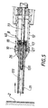
- the apparatus comprises a device 16 for returning the counterweight to the firing position comprising, in addition to the buffer guide 11, the guide ring 10, the spring 8 and the front barrel part 6 ′, with its groove 12, a ring of braking 17, and a pair of braking balls 18.
- the guide ring 10 is screwed onto an annular projection 19 of the buffer guide 11 ( Figure 4).
- the braking ring 17, slidably mounted on the buffer guide 11, has a rear portion 20 of enlarged inner section relative to that of the front portion corresponding substantially to that of the outer wall of the buffer guide, and it is extended towards the 'front by two lateral support arms 21 extending through slots 25 formed in the annular projection 19. Cutouts 22 formed in the enlarged portion 20 form tongues 23 elastically deformable radially.
- the buffer guide 11 At the rear of the buffer guide 11 are drilled, diametrically opposite, two recesses 24 in which are housed the braking balls 18.
- the balls have a diameter substantially equal to that of their receiving housings 24 but greater than the thickness of the buffer guide in which they are drilled.
- the buffer guide 11 moves back and, at the end of the pressing, it comes into contact with the centering ring 15 against the action of the spring 8 via of the guide ring 10.
- the braking ring 17 Due to the support of the buffer guide 11 against the centering ring 15, the braking ring 17 has been pushed forward so that it is the enlarged section portion 20 which is located in line with the balls 18 , not pushed back by the ring 17 towards the counterweight 13. Thus, no force being exerted on the balls, no resistance is applied to the rod of the counterweight 13 after ignition. The balls 18 not being in contact with the braking ring 17, they can roll freely on the counterweight rod.
- the barrel 6,6 ' is driven forward and the cartridge 5 is released.
- the guide ring 10 is driven forward by driving with it the buffer guide 11.
- the balls 18 roll on the counterweight 13 without effort and drive the braking ring 17, by the zone connecting its two portions of different sections, until the front end 26 of the ring 17 abuts against the front bottom 27 of the groove 12.
- the braking ring 17 slides backwards and its front portion, of "narrowed" section, comes into contact with the balls 18, pushes them radially towards the counterweight 13 to exert pressure on the counterweight and thus secure the buffer guide 11 and this flyweight 13.
- the buffer guide 11 After the introduction of a new buffer 1 into the buffer guide 11, when the apparatus is brought into contact again, against the action of the spring 8, the buffer guide 11, by the ring and the braking balls, drives the counterweight 13 in the firing position, before the centering ring 15 pushes the braking ring 17 forward and thus releases the balls 18 to separate the counterweight 13 from the buffer guide 11.
- the latter carries, behind the recesses 24 for receiving the braking balls 18, a rod 40 which performs two functions.
- the first is to prevent, by abutment effect, that the braking ring 17 does not separate from the buffer guide.
- the second function is to ensure a positive connection between the counterweight and the ring while still serving as a stop for the braking ring 17 which is pushed backwards under the action of the braking balls 18 subjected to the force of the counterweight 13 which, when the device is supported, tends to cause them to rotate.
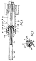
- a portion 131 of the rod of the counterweight 13 has a cross section of smaller diameter than that of the bore 111 of the buffer guide 11. Thanks to this, the balls of braking 18 can more easily protrude into the bore 111 without having to overcome the resistance of the counterweight rod. In addition, at the time of implementation support, the reaction of the balls 18 in contact with the counterweight rod 131 is more effective.
- the counterweight 13 has a portion of rod 131 with a narrowed section
- the braking ring 17 is rotatably mounted on the buffer guide 11 and in the return position under the action of a torsion spring 117 fixed to the braking ring 17 and to the guide ring 10
- the braking ring 17 has two internal recesses 217, for partially receiving the braking balls 18 allowing them to disappear and move away from the counterweight rod
- the braking ring 17 has an outer cam surface 317 intended to cooperate with a finger, fixed in rotation, of the barrel 6, to rotate it against the action of the torsion spring 117.
- This cam surface is in this case an inclined peripheral ramp, from the rear transverse edge 417 of the ring 17, both on the axis 30 of the device and on a perpendicular plane In this axis 30, that of Figure 7 for example, the finger of the barrel 6 projecting axially forward.
- the spring 8 drives the guide ring 10 and the buffer guide 11 forward until the front edge 106 of the ring 10 comes into abutment against the front bottom 27 of the groove 12, without neither the braking ring 17 nor the counterweight 13 having been moved relative to the buffer guide 11.
- the counterweight is released by rotation of the braking ring 17 by the finger of the barrel 6 and spacing of the balls 18 and reception in the recesses 217 of the ring 17.
Landscapes
- Engineering & Computer Science (AREA)
- Mechanical Engineering (AREA)
- Chemical & Material Sciences (AREA)
- Combustion & Propulsion (AREA)
- Portable Nailing Machines And Staplers (AREA)
- Clamps And Clips (AREA)
- Sheet Holders (AREA)
- Braking Arrangements (AREA)
- Closures For Containers (AREA)
- Heating, Cooling, Or Curing Plastics Or The Like In General (AREA)
- Sealing Devices (AREA)
- Seal Device For Vehicle (AREA)
- Absorbent Articles And Supports Therefor (AREA)
- Cable Accessories (AREA)
- Connector Housings Or Holding Contact Members (AREA)
- Pipe Accessories (AREA)
Applications Claiming Priority (2)
| Application Number | Priority Date | Filing Date | Title |
|---|---|---|---|
| FR9514763 | 1995-12-13 | ||
| FR9514763A FR2742375B1 (fr) | 1995-12-13 | 1995-12-13 | Appareil de scellement de tampons de fixation |
Publications (2)
| Publication Number | Publication Date |
|---|---|
| EP0779132A1 true EP0779132A1 (de) | 1997-06-18 |
| EP0779132B1 EP0779132B1 (de) | 2002-06-05 |
Family
ID=9485452
Family Applications (1)
| Application Number | Title | Priority Date | Filing Date |
|---|---|---|---|
| EP96402380A Expired - Lifetime EP0779132B1 (de) | 1995-12-13 | 1996-11-08 | Vorrichtung zum Festsetzen von Befestigungselementen |
Country Status (9)
| Country | Link |
|---|---|
| US (1) | US5881940A (de) |
| EP (1) | EP0779132B1 (de) |
| JP (1) | JPH09183078A (de) |
| KR (1) | KR100195827B1 (de) |
| AT (1) | ATE218415T1 (de) |
| AU (1) | AU676818B1 (de) |
| DE (1) | DE69621572T2 (de) |
| FR (1) | FR2742375B1 (de) |
| NZ (1) | NZ299885A (de) |
Cited By (1)
| Publication number | Priority date | Publication date | Assignee | Title |
|---|---|---|---|---|
| FR2772298A1 (fr) * | 1997-12-15 | 1999-06-18 | Hilti Ag | Outil de scellement actionne par des gaz a haute pression |
Families Citing this family (18)
| Publication number | Priority date | Publication date | Assignee | Title |
|---|---|---|---|---|
| DE19800847A1 (de) * | 1997-12-04 | 1999-06-17 | Gerd Dr Ing Kellner | Gerät zum Setzen eines Befestigungselementes in einen Setzuntergrund und Verwendung des Gerätes |
| FR2786420B1 (fr) | 1998-11-30 | 2001-01-05 | Prospection & Inventions | Procede de pose d'une embase de fixation de piece et outil de fixation pour la mise en oeuvre du procede |
| DE19962696C1 (de) * | 1999-12-23 | 2001-06-07 | Hilti Ag | Brennkraftbetriebenes Arbeitsgerät mit Bremseinrichtung für seinen Kolben |
| DE10105880C2 (de) * | 2001-02-09 | 2003-04-10 | Hilti Ag | Kolbenhalterung |
| DE10105879C2 (de) * | 2001-02-09 | 2002-12-12 | Hilti Ag | Kolbenhalterung |
| DE10105885C1 (de) * | 2001-02-09 | 2002-06-13 | Hilti Ag | Kolbenhalterung |
| DE10105882C2 (de) * | 2001-02-09 | 2002-12-05 | Hilti Ag | Kolbenhalterung |
| US6679411B2 (en) * | 2001-12-21 | 2004-01-20 | Illinois Tool Works Inc. | Piston retention system for a fastener driving tool |
| DE10254964B4 (de) * | 2002-11-26 | 2014-02-13 | Hilti Aktiengesellschaft | Setzgerät |
| FR2848489B1 (fr) * | 2002-12-11 | 2006-02-03 | Prospection & Inventions | Appareil de scellement a tir indirect |
| US9566692B2 (en) * | 2011-04-05 | 2017-02-14 | Ingersoll-Rand Company | Rotary impact device |
| US9463557B2 (en) | 2014-01-31 | 2016-10-11 | Ingersoll-Rand Company | Power socket for an impact tool |
| US10427277B2 (en) | 2011-04-05 | 2019-10-01 | Ingersoll-Rand Company | Impact wrench having dynamically tuned drive components and method thereof |
| JP2013111719A (ja) * | 2011-11-30 | 2013-06-10 | Makita Corp | 打込み工具 |
| EP2923799A1 (de) * | 2014-03-28 | 2015-09-30 | HILTI Aktiengesellschaft | Eintreibgerät |
| CN110757413B (zh) * | 2018-07-26 | 2022-08-26 | 创科无线普通合伙 | 气动工具 |
| US11338420B2 (en) * | 2019-12-18 | 2022-05-24 | Wang-Kuan Lin | Powder actuated nail gun |
| US11453107B2 (en) * | 2020-02-21 | 2022-09-27 | Joe Lin | Apparatus for installing explosively driven fasteners |
Citations (6)
| Publication number | Priority date | Publication date | Assignee | Title |
|---|---|---|---|---|
| DE1058950B (de) | 1951-07-12 | 1959-06-04 | Pierre Termet | Geraet zum Eintreiben von Bolzen od. dgl. in Steinwaende oder andere Aufnahme-koerper mittels eines durch Pulvergase beaufschlagbaren Kolbens |
| GB943640A (en) * | 1960-09-26 | 1963-12-04 | Olin Mathieson | Explosive actuated tools for driving studs or other fastener elements |
| DE1478814A1 (de) * | 1962-12-24 | 1969-03-06 | Bettermann Elektro Ohg | Setzgeraet zum Eintreiben von Bolzen od.dgl. in ein Bauteil mittels einer Treibladung |
| US4533077A (en) * | 1981-12-28 | 1985-08-06 | Hilti Aktiengesellschaft | Stop device for a driving piston in a fastening member setting device |
| EP0346275A1 (de) | 1988-06-10 | 1989-12-13 | HILTI Aktiengesellschaft | Pulverkraftbetriebenes Setzgerät |
| DE4313504A1 (de) * | 1993-04-24 | 1994-10-27 | Hilti Ag | Pulverkraftbetriebenes Setzgerät |
Family Cites Families (5)
| Publication number | Priority date | Publication date | Assignee | Title |
|---|---|---|---|---|
| US4358041A (en) * | 1980-06-12 | 1982-11-09 | Olin Corporation | Powder-actuated tool with power adjustment and angle-fire control |
| US4349141A (en) * | 1980-06-12 | 1982-09-14 | Olin Corporation | Piston return for powder actuated piston tool |
| DE3241528C2 (de) * | 1982-11-10 | 1986-04-10 | Eugen Lutz GmbH u. Co Maschinenfabrik, 7130 Mühlacker | Werkzeugspannfutter für einen Bohrhammer |
| US4651912A (en) * | 1985-05-28 | 1987-03-24 | Uniset Corporation | Hammer-activated fastener tool |
| US5269450A (en) * | 1993-02-10 | 1993-12-14 | Illinois Tool Works, Inc. | Hammer-strikable, powder-actuated, fastener-driving tool |
-
1995
- 1995-12-13 FR FR9514763A patent/FR2742375B1/fr not_active Expired - Fee Related
-
1996
- 1996-10-21 AU AU70299/96A patent/AU676818B1/en not_active Ceased
- 1996-10-29 KR KR1019960049368A patent/KR100195827B1/ko not_active Expired - Fee Related
- 1996-11-08 EP EP96402380A patent/EP0779132B1/de not_active Expired - Lifetime
- 1996-11-08 AT AT96402380T patent/ATE218415T1/de not_active IP Right Cessation
- 1996-11-08 DE DE69621572T patent/DE69621572T2/de not_active Expired - Lifetime
- 1996-12-05 NZ NZ299885A patent/NZ299885A/en unknown
- 1996-12-13 JP JP8334139A patent/JPH09183078A/ja not_active Ceased
- 1996-12-13 US US08/766,256 patent/US5881940A/en not_active Expired - Fee Related
Patent Citations (6)
| Publication number | Priority date | Publication date | Assignee | Title |
|---|---|---|---|---|
| DE1058950B (de) | 1951-07-12 | 1959-06-04 | Pierre Termet | Geraet zum Eintreiben von Bolzen od. dgl. in Steinwaende oder andere Aufnahme-koerper mittels eines durch Pulvergase beaufschlagbaren Kolbens |
| GB943640A (en) * | 1960-09-26 | 1963-12-04 | Olin Mathieson | Explosive actuated tools for driving studs or other fastener elements |
| DE1478814A1 (de) * | 1962-12-24 | 1969-03-06 | Bettermann Elektro Ohg | Setzgeraet zum Eintreiben von Bolzen od.dgl. in ein Bauteil mittels einer Treibladung |
| US4533077A (en) * | 1981-12-28 | 1985-08-06 | Hilti Aktiengesellschaft | Stop device for a driving piston in a fastening member setting device |
| EP0346275A1 (de) | 1988-06-10 | 1989-12-13 | HILTI Aktiengesellschaft | Pulverkraftbetriebenes Setzgerät |
| DE4313504A1 (de) * | 1993-04-24 | 1994-10-27 | Hilti Ag | Pulverkraftbetriebenes Setzgerät |
Cited By (1)
| Publication number | Priority date | Publication date | Assignee | Title |
|---|---|---|---|---|
| FR2772298A1 (fr) * | 1997-12-15 | 1999-06-18 | Hilti Ag | Outil de scellement actionne par des gaz a haute pression |
Also Published As
| Publication number | Publication date |
|---|---|
| FR2742375B1 (fr) | 1998-02-13 |
| ATE218415T1 (de) | 2002-06-15 |
| AU676818B1 (en) | 1997-03-20 |
| JPH09183078A (ja) | 1997-07-15 |
| EP0779132B1 (de) | 2002-06-05 |
| KR970033611A (ko) | 1997-07-22 |
| FR2742375A1 (fr) | 1997-06-20 |
| DE69621572D1 (de) | 2002-07-11 |
| KR100195827B1 (ko) | 1999-06-15 |
| US5881940A (en) | 1999-03-16 |
| DE69621572T2 (de) | 2003-01-09 |
| NZ299885A (en) | 1998-04-27 |
Similar Documents
| Publication | Publication Date | Title |
|---|---|---|
| EP0779132B1 (de) | Vorrichtung zum Festsetzen von Befestigungselementen | |
| EP0308322B1 (de) | Indirekt wirkendes Setzgerät mit Leistungssteuerung | |
| FR2634132A1 (fr) | Dispositif de fixation notamment pour chaussure de ski de fond | |
| FR2658052A1 (fr) | Instrument de peinture par liquide. | |
| EP0002632B1 (de) | Verschleissnachstellvorrichtung für Bremsen und Bremse versehen mit einer solchen Vorrichtung | |
| FR2690370A1 (fr) | Appareil pour la pose d'elements de fixation, a masselotte, cliquet de rappel de masselotte et guide-tampon pivotant. | |
| FR2761631A1 (fr) | Appareil de scellement de tampon a retenue de canon effacable | |
| WO2001017831A1 (fr) | Servomoteur pneumatique a auto-assistance selective et controlee en effort | |
| FR2848897A1 (fr) | Outil de scellement a combustion pour elements de fixation | |
| FR2507547A1 (fr) | Crayon mecanique a avance de mine automatique | |
| CA2540651A1 (fr) | Instrument d'ecriture a bouton lateral | |
| CA2591973A1 (fr) | Cle a cliquet | |
| EP1428628B1 (de) | Setzgerät mit Treibkolben | |
| FR2820669A1 (fr) | Porte-piston | |
| FR2614597A1 (fr) | Dispositif pour actionner le changement de vitesses d'une bicyclette | |
| FR2723994A1 (fr) | Dispositif de commande d'embrayage a rattrapage d'usure | |
| EP1226769A1 (de) | Sportschuh mit in Querrichtung verstellbarer Spannvorrichtung | |
| EP1675732A1 (de) | Mechanischer schreibstift | |
| BE1005385A3 (fr) | Dispositif permettant la reduction du poids de depart de la detente d'une carabine. | |
| EP2359990B1 (de) | Sicherheitsmesser | |
| EP0349368B1 (de) | Einstellbare Scheibenbremse | |
| EP0106711A1 (de) | Betätigungshebel für Fahrradkettenschaltung | |
| FR2796140A1 (fr) | Dispositif de mise a feu pour artillerie par percussion d'une etoupille | |
| FR2859406A1 (fr) | Outil se scellement | |
| BE532085A (de) |
Legal Events
| Date | Code | Title | Description |
|---|---|---|---|
| PUAI | Public reference made under article 153(3) epc to a published international application that has entered the european phase |
Free format text: ORIGINAL CODE: 0009012 |
|
| AK | Designated contracting states |
Kind code of ref document: A1 Designated state(s): AT BE CH DE ES FR GB IT LI NL SE |
|
| 17P | Request for examination filed |
Effective date: 19971013 |
|
| 17Q | First examination report despatched |
Effective date: 20000119 |
|
| GRAG | Despatch of communication of intention to grant |
Free format text: ORIGINAL CODE: EPIDOS AGRA |
|
| GRAG | Despatch of communication of intention to grant |
Free format text: ORIGINAL CODE: EPIDOS AGRA |
|
| GRAH | Despatch of communication of intention to grant a patent |
Free format text: ORIGINAL CODE: EPIDOS IGRA |
|
| GRAH | Despatch of communication of intention to grant a patent |
Free format text: ORIGINAL CODE: EPIDOS IGRA |
|
| GRAA | (expected) grant |
Free format text: ORIGINAL CODE: 0009210 |
|
| AK | Designated contracting states |
Kind code of ref document: B1 Designated state(s): AT BE CH DE ES FR GB IT LI NL SE |
|
| PG25 | Lapsed in a contracting state [announced via postgrant information from national office to epo] |
Ref country code: AT Free format text: LAPSE BECAUSE OF FAILURE TO SUBMIT A TRANSLATION OF THE DESCRIPTION OR TO PAY THE FEE WITHIN THE PRESCRIBED TIME-LIMIT Effective date: 20020605 |
|
| REF | Corresponds to: |
Ref document number: 218415 Country of ref document: AT Date of ref document: 20020615 Kind code of ref document: T |
|
| REG | Reference to a national code |
Ref country code: GB Ref legal event code: FG4D Free format text: NOT ENGLISH |
|
| REG | Reference to a national code |
Ref country code: CH Ref legal event code: EP |
|
| REF | Corresponds to: |
Ref document number: 69621572 Country of ref document: DE Date of ref document: 20020711 |
|
| GBT | Gb: translation of ep patent filed (gb section 77(6)(a)/1977) |
Effective date: 20020729 |
|
| PG25 | Lapsed in a contracting state [announced via postgrant information from national office to epo] |
Ref country code: SE Free format text: LAPSE BECAUSE OF FAILURE TO SUBMIT A TRANSLATION OF THE DESCRIPTION OR TO PAY THE FEE WITHIN THE PRESCRIBED TIME-LIMIT Effective date: 20020905 |
|
| PG25 | Lapsed in a contracting state [announced via postgrant information from national office to epo] |
Ref country code: LI Free format text: LAPSE BECAUSE OF NON-PAYMENT OF DUE FEES Effective date: 20021130 Ref country code: CH Free format text: LAPSE BECAUSE OF NON-PAYMENT OF DUE FEES Effective date: 20021130 |
|
| PG25 | Lapsed in a contracting state [announced via postgrant information from national office to epo] |
Ref country code: ES Free format text: LAPSE BECAUSE OF FAILURE TO SUBMIT A TRANSLATION OF THE DESCRIPTION OR TO PAY THE FEE WITHIN THE PRESCRIBED TIME-LIMIT Effective date: 20021220 |
|
| PLBE | No opposition filed within time limit |
Free format text: ORIGINAL CODE: 0009261 |
|
| STAA | Information on the status of an ep patent application or granted ep patent |
Free format text: STATUS: NO OPPOSITION FILED WITHIN TIME LIMIT |
|
| 26N | No opposition filed |
Effective date: 20030306 |
|
| REG | Reference to a national code |
Ref country code: CH Ref legal event code: PL |
|
| PGFP | Annual fee paid to national office [announced via postgrant information from national office to epo] |
Ref country code: NL Payment date: 20051016 Year of fee payment: 10 |
|
| PGFP | Annual fee paid to national office [announced via postgrant information from national office to epo] |
Ref country code: GB Payment date: 20051102 Year of fee payment: 10 |
|
| PGFP | Annual fee paid to national office [announced via postgrant information from national office to epo] |
Ref country code: BE Payment date: 20051208 Year of fee payment: 10 |
|
| PG25 | Lapsed in a contracting state [announced via postgrant information from national office to epo] |
Ref country code: BE Free format text: LAPSE BECAUSE OF NON-PAYMENT OF DUE FEES Effective date: 20061130 |
|
| PGFP | Annual fee paid to national office [announced via postgrant information from national office to epo] |
Ref country code: IT Payment date: 20061130 Year of fee payment: 11 |
|
| PG25 | Lapsed in a contracting state [announced via postgrant information from national office to epo] |
Ref country code: NL Free format text: LAPSE BECAUSE OF NON-PAYMENT OF DUE FEES Effective date: 20070601 |
|
| GBPC | Gb: european patent ceased through non-payment of renewal fee |
Effective date: 20061108 |
|
| NLV4 | Nl: lapsed or anulled due to non-payment of the annual fee |
Effective date: 20070601 |
|
| PG25 | Lapsed in a contracting state [announced via postgrant information from national office to epo] |
Ref country code: GB Free format text: LAPSE BECAUSE OF NON-PAYMENT OF DUE FEES Effective date: 20061108 |
|
| BERE | Be: lapsed |
Owner name: SOC. DE PROSPECTION ET D'INVENTIONS TECHNIQUES *SP Effective date: 20061130 |
|
| PG25 | Lapsed in a contracting state [announced via postgrant information from national office to epo] |
Ref country code: IT Free format text: LAPSE BECAUSE OF NON-PAYMENT OF DUE FEES Effective date: 20071108 |
|
| PGFP | Annual fee paid to national office [announced via postgrant information from national office to epo] |
Ref country code: DE Payment date: 20091127 Year of fee payment: 14 |
|
| REG | Reference to a national code |
Ref country code: DE Ref legal event code: R119 Ref document number: 69621572 Country of ref document: DE Effective date: 20110601 Ref country code: DE Ref legal event code: R119 Ref document number: 69621572 Country of ref document: DE Effective date: 20110531 |
|
| PG25 | Lapsed in a contracting state [announced via postgrant information from national office to epo] |
Ref country code: DE Free format text: LAPSE BECAUSE OF NON-PAYMENT OF DUE FEES Effective date: 20110531 |
|
| PGFP | Annual fee paid to national office [announced via postgrant information from national office to epo] |
Ref country code: FR Payment date: 20121206 Year of fee payment: 17 |
|
| REG | Reference to a national code |
Ref country code: FR Ref legal event code: ST Effective date: 20140731 |
|
| PG25 | Lapsed in a contracting state [announced via postgrant information from national office to epo] |
Ref country code: FR Free format text: LAPSE BECAUSE OF NON-PAYMENT OF DUE FEES Effective date: 20131202 |