EP0779210A1 - Machine à former, remplir et sceller - Google Patents
Machine à former, remplir et sceller Download PDFInfo
- Publication number
- EP0779210A1 EP0779210A1 EP97200373A EP97200373A EP0779210A1 EP 0779210 A1 EP0779210 A1 EP 0779210A1 EP 97200373 A EP97200373 A EP 97200373A EP 97200373 A EP97200373 A EP 97200373A EP 0779210 A1 EP0779210 A1 EP 0779210A1
- Authority
- EP
- European Patent Office
- Prior art keywords
- forming
- tube
- web
- strip
- heat sealing
- Prior art date
- Legal status (The legal status is an assumption and is not a legal conclusion. Google has not performed a legal analysis and makes no representation as to the accuracy of the status listed.)
- Withdrawn
Links
- 238000007789 sealing Methods 0.000 claims abstract description 49
- 239000000463 material Substances 0.000 claims abstract description 21
- 238000011144 upstream manufacturing Methods 0.000 claims abstract description 6
- 230000001131 transforming effect Effects 0.000 claims abstract description 5
- 239000004698 Polyethylene Substances 0.000 description 4
- -1 polyethylene Polymers 0.000 description 4
- 229920000573 polyethylene Polymers 0.000 description 4
- 229910000746 Structural steel Inorganic materials 0.000 description 3
- 238000000034 method Methods 0.000 description 3
- 239000004743 Polypropylene Substances 0.000 description 2
- 239000004809 Teflon Substances 0.000 description 2
- 229920006362 Teflon® Polymers 0.000 description 2
- 238000005096 rolling process Methods 0.000 description 2
- 239000000853 adhesive Substances 0.000 description 1
- 238000010438 heat treatment Methods 0.000 description 1
- 229920001155 polypropylene Polymers 0.000 description 1
- 230000000630 rising effect Effects 0.000 description 1
- 229920001169 thermoplastic Polymers 0.000 description 1
- 239000004416 thermosoftening plastic Substances 0.000 description 1
- 239000002699 waste material Substances 0.000 description 1
Images

Classifications
-
- B—PERFORMING OPERATIONS; TRANSPORTING
- B65—CONVEYING; PACKING; STORING; HANDLING THIN OR FILAMENTARY MATERIAL
- B65B—MACHINES, APPARATUS OR DEVICES FOR, OR METHODS OF, PACKAGING ARTICLES OR MATERIALS; UNPACKING
- B65B9/00—Enclosing successive articles, or quantities of material, e.g. liquids or semiliquids, in flat, folded, or tubular webs of flexible sheet material; Subdividing filled flexible tubes to form packages
- B65B9/10—Enclosing successive articles, or quantities of material, in preformed tubular webs, or in webs formed into tubes around filling nozzles, e.g. extruded tubular webs
- B65B9/20—Enclosing successive articles, or quantities of material, in preformed tubular webs, or in webs formed into tubes around filling nozzles, e.g. extruded tubular webs the webs being formed into tubes in situ around the filling nozzles
- B65B9/213—Enclosing successive articles, or quantities of material, in preformed tubular webs, or in webs formed into tubes around filling nozzles, e.g. extruded tubular webs the webs being formed into tubes in situ around the filling nozzles the web having intermittent motion
-
- B—PERFORMING OPERATIONS; TRANSPORTING
- B65—CONVEYING; PACKING; STORING; HANDLING THIN OR FILAMENTARY MATERIAL
- B65B—MACHINES, APPARATUS OR DEVICES FOR, OR METHODS OF, PACKAGING ARTICLES OR MATERIALS; UNPACKING
- B65B61/00—Auxiliary devices, not otherwise provided for, for operating on sheets, blanks, webs, binding material, containers or packages
- B65B61/20—Auxiliary devices, not otherwise provided for, for operating on sheets, blanks, webs, binding material, containers or packages for adding cards, coupons or other inserts to package contents
- B65B61/202—Auxiliary devices, not otherwise provided for, for operating on sheets, blanks, webs, binding material, containers or packages for adding cards, coupons or other inserts to package contents for attaching articles to the outside of a container
Definitions
- the apparatus relates to a form, fill and seal apparatus, in particular to an apparatus for forming bags from a web of heat sealable material, filling them with a product and consequently sealing the bags by heat sealing.
- a rolled up web of, for example, polyethylene or polypropylene film is rolled off from a roll and guided over a forming shoulder with a forming tube, around which the film is wrapped to form a tube moving in the course of the further process downward over and from the forming tube.
- the forming shoulder is open at the top and and forms there the beginning of a filling sleeve for products which are to be put into the bags which extends vertically through the forming tube.
- Two double transversely disposed heat sealing rods are located on either side of the downwardly extending tube beneath the heat sealing rod, which are periodically moved towards each other in order to clamp the tube film between themselves and then to be activated to form a seal, after which a certain quantity of the product to be packed is dispensed, which will fall downward through the forming shoulder and the forming tube. At the same time the tube is pulled down over the rise of one bag by the heat sealing rods which still clamp the film tube.
- the double heat sealing rods are moved away from the film tube again, are moved to the top over the rise of a bag and are consequently brought into heat sealing engagement with the film tube so as to form at the same time the upper transverse seal of the bag just filled and the lower transverse seal of the bag following behind, which is still to be formed.
- a cutting means arranged between the double heat sealing rods is then activated, so that a bag, divided and sealed off by a longitudinal seam, an upper transverse seam and a lower transverse seam, and filled with the product is obtained.
- the film web can be printed with all kinds of information about the product to be packed into the future bags before it is delivered for use in the form, fill and seal apparatus. Printing the film web is done by a supply company. For each separate product the company using the form, fill and seal apparatus will have to have a separate roll of film web with the appropriate print for that product in stock.
- the bags are made of a film web material which is provided with holes, wherein the holes can be placed quite close to one another.
- the film web is provided with holes the surface thereof is less suitable for printing information onto; a large part of the illustrations and the letters can be lost.
- self-adhesive stickers are sometimes placed on the formed bags in a separate operation. This is, however, laborious and moreover results in a sometimes considerable number of the holes being closed off.
- the bag is then made up of several materials, this being disadvantageous for the possible retrieval for reuse of material from the future waste.
- Another way of providing information on the bags made of film web which is provided with holes consists of omitting the holes from a part of the film web so that there a strip is provided which is suitable to be printed on.
- the result is that two parts containing a different quantity of material can be distinguished in the film web, that is the part without holes and the part with holes. This difference in thickness gives rise to difficulties when rolling up the film web.
- An object of the invention is to provide a form, fill and seal machines which is an improvement on the circumstances described above.
- the invention provides an apparatus for forming bags from synthetic film, for filling and sealing them, comprising forming means for transforming a fed flat web of heat sealable material into a tubular form with overlapping margins, first heat sealing means for forming a longitudinal sealing seam in the formed tube at the overlapping margins by heat sealing and second heat sealing means for forming transverse sealing seams in the formed tube by heat sealing, as well as means for supplying a strip of the same material up to and parallel to the tubularly formed web at the location upstream from the second heat sealing means which form the transverse sealing seam and downstream from the location where the film web is transformed to a tube.
- the fed strip of heat sealable material can serve here as an information carrier so that the film web itself does not have to be printed on beforehand. In this way far less material in roll form need be kept in stock. Only the rolls with the strip will each be related to a certain product and these rolls with strips will take up less space and contain less material than the rolls of film web.
- the strip which is of the same material as the heat sealable film web material, will simultaneously be sealed at the location of the second heat sealing means which form the transverse sealing seams.
- the film web is provided with holes no part of the surface of the film web need be realized as being closed, but instead a film web with a regular hole pattern can be used. In spite of this, a sufficient information carrying area is provided by the strip.
- the strip feeding during the bag forming process no special operations are required.
- the only thing that has to be taken care of is that the roll of the strip is replaced in time and that the strip is introduced into the apparatus in the correct way. Not only the film tube and with that the film web are moved through the apparatus by the activated second heat sealing means, which form the transverse seams, but also a length of strip from the roll of the strip material is unrolled.
- the supply means for the strip are adapted to supply the strip at a location aligned with and upstream from the first heat sealing means up to and parallel to the tubularly formed web.
- the strip is sealed together with the overlapping margins by the first heat sealing means, that is over the whole length of the future bag.
- the form means are adapted for transforming the film web into a film tube advancing in a downward direction.
- this closing strip is sealed on the one hand to the margin and on the other hand to the other margin.
- the closing strip is provided with intermating profiles, which form a resealable upper opening of the finished bag during use.
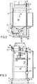
- the form, fill and seal machine 1 in figures 1, 2, and 3 comprises a frame 2 which can be placed on a fixed base by means of adjustable legs 4.
- An electric driving unit 26, a housing 27, a control cabinet 3 and a roll holder 5 are placed on the frame 2.
- the roll holder comprises a post 28, on the upper end of which a transverse shaft is rotatably attached.
- This transverse shaft 6 is free at its other end, so that a roll 7 of synthetic monofilm, for example PE can easily be put thereon.
- the film can be provided with holes on its entire surface.
- the housing 27 On the righthand side (figure 1) of the housing 27 outriggers 10 are hingedly and resiliently attached on either side thereof, between which compensation rolls 9 are arranged. On its upper surface the housing 27 forms a guiding table 29 over which a film web B, originating from the roll 7, can be supported and guided. On either side of the guiding surface 29 there are guiding rails 11 which are provided with follower rolls 12 at their upstream ends, which are supported in the guiding rails 11 with their ends, the follower rails being situated above the compensation rolls 9.
- a combined forming shoulder/filling funnel 8 is placed, whereby the feed funnel merges into a forming tube 33 at its lower end.
- the combined forming shoulder/filling funnel is supported on projecting ends of the guiding rails 11 and on outrigger 13, attached to the housing 27.
- a roll 16 of printed strip material 5 made of PP is rotatably put onto a shaft 17.
- a first angle iron is attached, consisting of a vertical attachment plate, which is welded to the rail 11, and a horizontal strip feed-through plate 19, provided with a strip feed-through slot 19' situated at 45° in relation to a vertical longitudinal plane of the apparatus.
- a second angle iron 20 is arranged, supported by a transverse rod 30, which itself is carried by the rail 11.
- the angle iron 20 comprises a horizontal strip feed-through plate 21 which is provided with a strip feed-through slot 20' arranged at 45° in relation to the previously mentioned longitudinal plane and a strip feed-through plate 22 rising vertically from the plate 21, provided with a horizontal strip feed-through slot 22'.
- the plate 22 is located at a minor distance in front of the surface of the forming tube 33, where the overlapping margins of the film web which has been transformed into a tube will be situated during operation of the apparatus.
- a transverse rod 31 is mounted to move back and forth in the E directions.
- a heated longitudinal seam forming rod 14 is perpendicularly arranged on this cross rod 31 which together with the cross rod 31 can be moved to the surface of the forming tube 33 and away from it again.
- the rod 14 is of a length minimally equal to the height of the bag and is covered with a layer of teflon.
- the arrangement is such that the strip feed-through plate 22 is placed immediately above the upper end of the longitudinal seam forming rod 14.
- an outrigger 32 is mounted to the housing 27 to move back and forth in the F directions.
- Two transversely placed support rods 25 are mounted on the outrigger 32 which are movable towards and away from each other in the D directions.
- On their surfaces facing each other the transverse rods 25 carry heated transverse seam forming double rods 15.
- a cutting means (not shown) is located between each of the double rods 15. These rods too are provided with a teflon covering.
- the space in which the sealing seam forming rods are arranged and where they move is screened off by means of a movable, transparent panel 20.
- All movable parts of the apparatus 1 can be operated pneumatically.
- a roll of film web 7 is put on the shaft 6 of a roll holder 5.
- the film web B is manually rolled off over a certain length and guided about the compensation rolls 9 and the follower rolls 12, as can be seen in figur 1, and then laid over the guiding table 29, laid about the forming shoulder 8 and guided about the forming tube 12 so that the film web acquires a tubular form, all this until the then tubular film web extends up to below the working area of the transverse seam forming rods 15.
- a delivery apparatus for products to be packed in bags, which is adjusted for delivering suitable doses is placed above the forming shoulder/filling funnel.
- the apparatus 1 is then put into working order by allowing it to operate for a while without being fed with products.
- the transverse seam forming rods 15 are operated so as to clamp the tube film B in between themselves and to pull it downward over a distance equal to the height of the bag to be formed. Because the transverse seam forming rods 15 tightly clamp the film web, during this stroke period the film web B is pulled and will be rolled off and will move along in the direction of arrow A.
- the strip 5 has also been prepared by rolling it off over a length of the roll 16 in direction G (figure 4), bringing it up to the strip feed-through slot 19,' inserting it through there from below to above, bringing it subsequently in direction H up to below the plate 21, and inserting the strip S from below to above through the feed-through slot 22' up to the forming tube 12 (figure 4) and finally leading it directly downward in direction I up to the operating area of the transverse seam forming rods 15.
- the rods 15 therefore clamp the film tube B and pull it along in their descending movement not only the roll 7 of the film web B is rolled off, but also the roll 16 of the strip S.
- the stroke period ends and the rods 15 are moved away from each other so that the film tube is no longer clamped.
- the film web B and the strip S will then come to a standstill.
- the transverse rod 31 is moved towards the forming tube 12 in the E direction until the longitudinal seam forming rod 14 presses the film tube B against the forming tube 33.
- the film web B is led in such a way about the forming shoulder and the forming tube 33, that in the area of contact with the longitudinal seam forming rod 14 an overlap area is located, where the longitudinal margins of the film web B are placed over each other.
- the strip S is located between the rod 14 and the overlap area so that at the same time the strip S is welded by the rod 14 onto the overlap area and the overlap area is sealed by the heat sealing.
- the product delivery apparatus too - not shown - is brought into action.
- a start is made with the stroke period in which the transverse seam forming rods 15 are moved towards each other to clamp the film tube B.
- the heating elements in the transverse seam forming rods 15 are operated so that a double transverse sealing seam is formed by heat sealing.
- the strip S is sealed as well.
- a command is given by suitable means to the delivery apparatus to release a measured quantity of products, this measured quantity falling into the filling funnel 8 and through the forming tube 12 into the film tube B, until this quantity of products is restrained at the lower end of the film tube B which is closed by the transverse seam forming rods.
- transverse seam forming rods 15 are each made up of two heated rods placed above one another, an upper seam of the lowest, previous bag and a bottom seam of the subsequent bag are formed simultaneously. Between these double heated rods a knife (not shown) is arranged, which is operated when the transverse seam forming rods 15 have arrived at the end of the descending stroke. At the end of every stroke a filled, cut off bag will therefore be delivered.
- the vertical stroke can be continuously adjusted by a hand wheel 23.
- the compensation- and follower rolls 9 and 12 ensure that the film web B remains under tension.
- film bags filled with a measured out quantity of product are delivered by the apparatus 1 on the lefthand side thereof, the bags being sealed by means of a bottom seam, a top seam and a longitudinal seam, wherein also a strip extending over the length of the bag is sealed onto the longitudinal seam, on which the information relating to the product is printed.
Landscapes
- Engineering & Computer Science (AREA)
- Mechanical Engineering (AREA)
- Containers And Plastic Fillers For Packaging (AREA)
- Seal Device For Vehicle (AREA)
- Making Paper Articles (AREA)
- Ropes Or Cables (AREA)
Applications Claiming Priority (5)
| Application Number | Priority Date | Filing Date | Title |
|---|---|---|---|
| NL9200526 | 1992-03-23 | ||
| NL9200526A NL9200526A (nl) | 1992-03-23 | 1992-03-23 | Vorm-, vul- en sluitmachine. |
| NL9200527A NL9200527A (nl) | 1992-03-23 | 1992-03-23 | Vorm-, vul en sluitmachine. |
| NL9200527 | 1992-03-23 | ||
| EP93200834A EP0562690B1 (fr) | 1992-03-23 | 1993-03-23 | Machine à former, remplir et sceller |
Related Parent Applications (1)
| Application Number | Title | Priority Date | Filing Date |
|---|---|---|---|
| EP93200834.5 Division | 1993-03-23 |
Publications (1)
| Publication Number | Publication Date |
|---|---|
| EP0779210A1 true EP0779210A1 (fr) | 1997-06-18 |
Family
ID=26646953
Family Applications (2)
| Application Number | Title | Priority Date | Filing Date |
|---|---|---|---|
| EP97200373A Withdrawn EP0779210A1 (fr) | 1992-03-23 | 1993-03-23 | Machine à former, remplir et sceller |
| EP93200834A Expired - Lifetime EP0562690B1 (fr) | 1992-03-23 | 1993-03-23 | Machine à former, remplir et sceller |
Family Applications After (1)
| Application Number | Title | Priority Date | Filing Date |
|---|---|---|---|
| EP93200834A Expired - Lifetime EP0562690B1 (fr) | 1992-03-23 | 1993-03-23 | Machine à former, remplir et sceller |
Country Status (3)
| Country | Link |
|---|---|
| EP (2) | EP0779210A1 (fr) |
| AT (1) | ATE157316T1 (fr) |
| DE (1) | DE69313332T2 (fr) |
Families Citing this family (1)
| Publication number | Priority date | Publication date | Assignee | Title |
|---|---|---|---|---|
| DE102013225051A1 (de) | 2013-01-08 | 2014-07-10 | Robert Bosch Gmbh | Vorrichtung zum Aufbringen einer ein Auftragsbild aufweisenden Klebstoffschicht auf eine endlose Verpackungsmaterialbahn sowie Verwendung einer Vorrichtung |
Citations (2)
| Publication number | Priority date | Publication date | Assignee | Title |
|---|---|---|---|---|
| US4894975A (en) * | 1988-03-09 | 1990-01-23 | Minigrip, Inc. | Method and apparatus for making reclosable bags with fastener strips in a form fill and seal machine |
| US5046300A (en) * | 1990-10-19 | 1991-09-10 | Reynolds Consumer Products, Inc. | Method and apparatus for forming a reclosable package |
Family Cites Families (5)
| Publication number | Priority date | Publication date | Assignee | Title |
|---|---|---|---|---|
| US3557525A (en) * | 1968-01-18 | 1971-01-26 | Hesser Ag Maschf | Apparatus for making and filling bags |
| NL7513157A (en) * | 1975-11-10 | 1977-05-12 | Procter & Gamble | Equipment for making successive sachets of absorbent wadding - with automatic filling and provision of a pull cord |
| US4077308A (en) * | 1976-06-04 | 1978-03-07 | Pneumatic Scale Corporation | Control for bag making machine |
| US4322929A (en) * | 1980-03-12 | 1982-04-06 | The Specialty Papers Company | Packaging method using an adhesive coated web |
| US4517787A (en) * | 1982-08-17 | 1985-05-21 | Frito-Lay, Inc. | Method and apparatus for sealing bags |
-
1993
- 1993-03-23 EP EP97200373A patent/EP0779210A1/fr not_active Withdrawn
- 1993-03-23 EP EP93200834A patent/EP0562690B1/fr not_active Expired - Lifetime
- 1993-03-23 AT AT93200834T patent/ATE157316T1/de not_active IP Right Cessation
- 1993-03-23 DE DE69313332T patent/DE69313332T2/de not_active Expired - Fee Related
Patent Citations (3)
| Publication number | Priority date | Publication date | Assignee | Title |
|---|---|---|---|---|
| US4894975A (en) * | 1988-03-09 | 1990-01-23 | Minigrip, Inc. | Method and apparatus for making reclosable bags with fastener strips in a form fill and seal machine |
| US4894975B1 (fr) * | 1988-03-09 | 1991-12-03 | Minigrip Inc | |
| US5046300A (en) * | 1990-10-19 | 1991-09-10 | Reynolds Consumer Products, Inc. | Method and apparatus for forming a reclosable package |
Also Published As
| Publication number | Publication date |
|---|---|
| EP0562690B1 (fr) | 1997-08-27 |
| ATE157316T1 (de) | 1997-09-15 |
| EP0562690A2 (fr) | 1993-09-29 |
| EP0562690A3 (en) | 1993-12-01 |
| DE69313332D1 (de) | 1997-10-02 |
| DE69313332T2 (de) | 1998-03-26 |
Similar Documents
| Publication | Publication Date | Title |
|---|---|---|
| US3977152A (en) | Method and apparatus for automatically packaging flexible flat goods | |
| US4581764A (en) | Sack, and a method and apparatus for filling, removing air from, and closing the sack | |
| US2847806A (en) | Packing machines | |
| US4452597A (en) | Method and apparatus for forming stacks of sacks | |
| RU2228888C2 (ru) | Способ и система расфасовки товаров в пакеты, подаваемые из взаимосвязанных серий пакетов | |
| US6393809B2 (en) | Servo-controlled pouch making apparatus | |
| US4353196A (en) | Package and automatic method of forming same | |
| US4586318A (en) | Bag forming and bagger apparatus and method | |
| US4548018A (en) | Apparatus for horizontally forming, filling and sealing film pouch material | |
| EP0999130A2 (fr) | Machine d'emballage possédant un mode d'opération continu et intermittant | |
| US6481184B1 (en) | Method and apparatus for fastening of tubular bags on a hanger strip | |
| GB1195959A (en) | Packaging Method and Machine for Forming and Filling Bags of Different Lenghts and Widths. | |
| JPH02180105A (ja) | 包装機械 | |
| EP0187803A1 (fr) | Machine de fabrication de blague a tabac | |
| US3952480A (en) | Packaging apparatus | |
| WO2007106916A1 (fr) | Machine de formage, remplissage, scellage verticale a mouvement continu | |
| CA2273415C (fr) | Appareil et methode de fabrication et d'emballage de sacs en aluminium | |
| US3938299A (en) | Packaging system and method | |
| US2928217A (en) | Process and apparatus for wrapping bales | |
| US3557525A (en) | Apparatus for making and filling bags | |
| US3331183A (en) | Sealing packages | |
| US3221474A (en) | Automatic packaging machine | |
| EP0779210A1 (fr) | Machine à former, remplir et sceller | |
| US3319539A (en) | Machine for making double-wall packages | |
| US3594978A (en) | Apparatus for packaging articles |
Legal Events
| Date | Code | Title | Description |
|---|---|---|---|
| PUAI | Public reference made under article 153(3) epc to a published international application that has entered the european phase |
Free format text: ORIGINAL CODE: 0009012 |
|
| AC | Divisional application: reference to earlier application |
Ref document number: 562690 Country of ref document: EP |
|
| AK | Designated contracting states |
Kind code of ref document: A1 Designated state(s): BE DE DK ES FR GB IT NL SE |
|
| 17P | Request for examination filed |
Effective date: 19971119 |
|
| 17Q | First examination report despatched |
Effective date: 19990113 |
|
| GRAG | Despatch of communication of intention to grant |
Free format text: ORIGINAL CODE: EPIDOS AGRA |
|
| 17Q | First examination report despatched |
Effective date: 19990113 |
|
| GRAG | Despatch of communication of intention to grant |
Free format text: ORIGINAL CODE: EPIDOS AGRA |
|
| GRAH | Despatch of communication of intention to grant a patent |
Free format text: ORIGINAL CODE: EPIDOS IGRA |
|
| STAA | Information on the status of an ep patent application or granted ep patent |
Free format text: STATUS: THE APPLICATION IS DEEMED TO BE WITHDRAWN |
|
| 18D | Application deemed to be withdrawn |
Effective date: 20001201 |