EP0779237A2 - Grue mobile avec un appareil de sécurité anti-surcharge - Google Patents
Grue mobile avec un appareil de sécurité anti-surcharge Download PDFInfo
- Publication number
- EP0779237A2 EP0779237A2 EP96118130A EP96118130A EP0779237A2 EP 0779237 A2 EP0779237 A2 EP 0779237A2 EP 96118130 A EP96118130 A EP 96118130A EP 96118130 A EP96118130 A EP 96118130A EP 0779237 A2 EP0779237 A2 EP 0779237A2
- Authority
- EP
- European Patent Office
- Prior art keywords
- boom
- rotation
- sliding
- angle
- overload protection
- Prior art date
- Legal status (The legal status is an assumption and is not a legal conclusion. Google has not performed a legal analysis and makes no representation as to the accuracy of the status listed.)
- Granted
Links
- 238000013459 approach Methods 0.000 claims description 5
- 238000012806 monitoring device Methods 0.000 claims description 5
Images
Classifications
-
- B—PERFORMING OPERATIONS; TRANSPORTING
- B66—HOISTING; LIFTING; HAULING
- B66C—CRANES; LOAD-ENGAGING ELEMENTS OR DEVICES FOR CRANES, CAPSTANS, WINCHES, OR TACKLES
- B66C23/00—Cranes comprising essentially a beam, boom, or triangular structure acting as a cantilever and mounted for translatory of swinging movements in vertical or horizontal planes or a combination of such movements, e.g. jib-cranes, derricks, tower cranes
- B66C23/88—Safety gear
- B66C23/90—Devices for indicating or limiting lifting moment
Definitions
- the invention relates to a crane vehicle with an overload protection device, with a boom articulated on its superstructure, preferably a telescopic boom, which can be rocked by a rocker cylinder articulated on this and the superstructure, with extendable sliding spars arranged on the opposite end regions of the long sides of the undercarriage Ends are provided with extendable support feet, and with a device measuring the angle of rotation of the boom, the signals of which are fed to a processing device of the overload protection device, in which the overload protection device generates a warning signal and / or stops the crane operation when the crane approaches or exceeds its stability-threatening limits .
- the stability of a crane vehicle with a telescopic boom depends not only on the size of the load hanging on the telescopic boom, but also on the luffing angle, the extension length of the telescopic boom, the deflection of the telescopic boom and in particular also on the angle of rotation of the uppercarriage with the telescopic boom to the undercarriage and the support legs of the sliding beams defined stand square.
- the safety of the crane is greatest when the boom points in the direction of the most extended sliding beam.
- Sliding bars with extended support feet ensure greater stability in the longitudinal direction of the undercarriage than in the direction of its transverse axis.
- the overload safety device must therefore always take into account the extended state of the sliding struts, which is problematic in that the stability changes even with different extending lengths of the individual sliding struts.
- the object of the invention is therefore to create a crane vehicle of the type specified at the outset, in which the overload protection device reliably takes into account the different extension lengths of the sliding struts.
- this object is achieved in a crane vehicle of the type specified at the outset in that a monitoring device is provided which detects the extension state or the extension length of the sliding spars, which supplies the signals of the overload protection device corresponding to the respective extension length of the individual sliding spars, and that the processing device of the overload protection device from the Signals of the monitoring device for the extension length of the sliding spars and from the signals of the device measuring the angle of rotation of the boom for each angle of rotation of the boom determine the stability of the standing square resulting from the extended state of the sliding spars.
- the signals generated by the angle of rotation measuring device and the monitoring device of the sliding spars in accordance with the angle of rotation or the extension lengths of the sliding spars are processed by the processing device, which contains a microcomputer, by comparison with the other values determining the stability, the overload protection device generating a signal stopping the crane operation when the crane approaches or exceeds its stability-threatening limits.
- the 360 ° rotation angle of the boom is divided into a plurality of rotation angle ranges and that for each of these rotation angle ranges, the booms located in this area result from the extension lengths of the Stability safety values resulting in sliding beams are stored in a table (bit map), from which the processing unit reads the current stability values of the standing square in accordance with the measured extension lengths of the sliding beams.
- each sliding beam has only three support positions in which it is bolted, namely once a retracted position in which the support foot is located in the area of the longitudinal side of the undercarriage, a middle position and a fully extended position . If only these three support positions are taken into account when calculating the stability for each of the four sliding spars, the safety values for each of the areas can be stored in a clear table.
- the computing work of the processing device can be reduced even further by dividing the 360 ° angle of rotation of the boom into four quadrants for determining the stability values of the standing rectangle. For each of these four quadrants, the stability values for all possible extension lengths of the sliding beams are stored in such a way that the smallest values valid for them are valid for the entire quadrant.
- the angular ranges lying in the safety range are determined from the measured values of the angle of rotation of the boom and the extension lengths of the sliding beams which the boom can be rotated at a predetermined load to a predetermined smallest luffing angle of the boom.
- variable angular ranges are defined in which the boom can be rotated safely with the load attached to it. For each of these angular ranges, the smallest rocking angle that is permissible in this angular range is assumed. This definition of variable angular ranges also simplifies the calculation since the permissible safety values do not have to be taken into account for every angle of the jib.
- the reduction in the angular ranges has the advantage that the crane operator does not have to fear in larger angular ranges to approach an angular limit at which the overload safety device responds.
- the choice of larger angular ranges means that the higher loads that are permissible in certain areas, for example by pivoting the boom to smaller luffing angles, cannot be used in these.
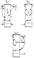
- FIG. 1 schematically shows an undercarriage 1 of a crane vehicle, from which the sliding spars 2 are extended to different extents, which support legs 3 at their ends, which can be extended vertically against the ground by hydraulic cylinders at right angles to the sliding spars. Threaded spindles can also be provided to extend the support feet.
- the sliding beams 2 are located in the end regions of the two long sides of the undercarriage 1 and can be extended at right angles to its longitudinal center plane.
- the sliding beams can be extended in three stages, in which they must each be bolted in their guides. These steps correspond to a retracted position in which the support lengths of the sliding spars are smallest, an intermediate position and an extended position in which the support length is greatest.
- the two sliding beams 2 on the left side are in their middle position, the upper sliding beam on the right side in its most extended position and the sliding beam on the lower right in its retracted position Position.
- This extension pattern of the sliding spars and the resulting support lengths result in a standing square, which is able to take up different rocking forces over the angle of rotation of the boom.
- angular ranges have been defined in the standing square, which result from the lines drawn from the axis of rotation 4 of the boom to the ends of the sliding spars 2 or through the support lines of the support feet 3.
- certain permissible cantilever moments have been defined, the different sizes of which are indicated by the radius of the circular arc spanning the angular ranges.
- a uniform permissible cantilever torque is defined for each angular range, which corresponds to the largest permissible cantilever torque for this angular range.
- the different four-angle ranges resulting from the different extension lengths of the sliding beams as well as the largest cantilever moments permitted for each of these angle ranges are stored in a payload table from which these values can be read out for processing in the processing unit with the overload protection device.
Landscapes
- Engineering & Computer Science (AREA)
- Mechanical Engineering (AREA)
- Jib Cranes (AREA)
Applications Claiming Priority (2)
| Application Number | Priority Date | Filing Date | Title |
|---|---|---|---|
| DE29519928U DE29519928U1 (de) | 1995-12-15 | 1995-12-15 | Kranfahrzeug mit einer Überlastsicherungseinrichtung |
| DE29519928U | 1995-12-15 |
Publications (3)
| Publication Number | Publication Date |
|---|---|
| EP0779237A2 true EP0779237A2 (fr) | 1997-06-18 |
| EP0779237A3 EP0779237A3 (fr) | 1997-07-09 |
| EP0779237B1 EP0779237B1 (fr) | 2001-10-10 |
Family
ID=8016782
Family Applications (1)
| Application Number | Title | Priority Date | Filing Date |
|---|---|---|---|
| EP96118130A Expired - Lifetime EP0779237B1 (fr) | 1995-12-15 | 1996-11-12 | Grue mobile avec un appareil de sécurité anti-surcharge |
Country Status (5)
| Country | Link |
|---|---|
| US (1) | US5887735A (fr) |
| EP (1) | EP0779237B1 (fr) |
| JP (1) | JPH09175785A (fr) |
| KR (1) | KR100427506B1 (fr) |
| DE (2) | DE29519928U1 (fr) |
Cited By (5)
| Publication number | Priority date | Publication date | Assignee | Title |
|---|---|---|---|---|
| EP1925585A1 (fr) * | 2006-11-21 | 2008-05-28 | Liebherr-Werk Ehingen GmbH | Grue mobile |
| CN105271025A (zh) * | 2014-06-03 | 2016-01-27 | 利勃海尔工厂埃英根有限公司 | 具有支腿和用于加宽支撑基座的加长梁的移动式作业机械 |
| IT201700037143A1 (it) * | 2017-04-05 | 2018-10-05 | Jacques Tranchero | Gru con sistema antiribaltamento settoriale |
| CN108892038A (zh) * | 2018-06-07 | 2018-11-27 | 河南华电工控技术有限公司 | 一种起重机械远程无线安全监控管理系统 |
| US11142438B2 (en) | 2017-08-28 | 2021-10-12 | Manitowoc Crane Companies, Llc | Graphical working range diagrams for displaying allowable and projected loads |
Families Citing this family (16)
| Publication number | Priority date | Publication date | Assignee | Title |
|---|---|---|---|---|
| US6269635B1 (en) | 1999-01-20 | 2001-08-07 | Manitowoc Crane Group, Inc. | Control and hydraulic system for a liftcrane |
| JP3683571B2 (ja) * | 2003-04-10 | 2005-08-17 | 古河機械金属株式会社 | クレーンの転倒防止装置 |
| DE202005013310U1 (de) * | 2005-08-23 | 2007-01-04 | Liebherr-Hydraulikbagger Gmbh | Überlastwarneinrichtung für Bagger |
| WO2007033273A2 (fr) * | 2005-09-13 | 2007-03-22 | Romer Incorporated | Véhicule muni d’un dispositif d’articulation |
| DE102006031257A1 (de) * | 2006-07-06 | 2008-01-10 | Putzmeister Ag | Autobetonpumpe mit Knickmast |
| DE102008055625A1 (de) * | 2008-11-03 | 2010-05-06 | Putzmeister Concrete Pumps Gmbh | Fahrbare Arbeitsmaschine mit Stützauslegern |
| CN101746675B (zh) * | 2009-12-31 | 2012-05-02 | 三一汽车制造有限公司 | 起重机超起装置及其控制系统和控制方法 |
| DE102010056584B4 (de) | 2010-12-30 | 2018-03-29 | Asm Automation Sensorik Messtechnik Gmbh | Mobile Arbeitsmaschine |
| AT511234B1 (de) * | 2011-04-08 | 2013-05-15 | Palfinger Ag | Standsicherheitsüberwachung eines auf einem fahrzeug montierten ladekrans |
| DE102011119654B4 (de) * | 2011-11-29 | 2015-11-12 | Liebherr-Werk Ehingen Gmbh | Mobile Arbeitsmaschine, insbesondere Fahrzeugkran |
| DE102012011871B4 (de) * | 2012-06-13 | 2020-09-03 | Liebherr-Werk Ehingen Gmbh | Verfahren zur Überwachung der Kransicherheit sowie Kran |
| AT13517U1 (de) * | 2012-10-19 | 2014-02-15 | Palfinger Ag | Sicherheitseinrichtung für einen Kran |
| CN103043581B (zh) * | 2012-12-21 | 2016-04-06 | 三一重工股份有限公司 | 一种转台限位装置、方法及工程机械 |
| DE102013201860A1 (de) * | 2013-02-05 | 2014-08-07 | Terex Cranes Germany Gmbh | Verfahren zur Beeinflussung einer auf einen Seiltrieb wirkenden Seilwindenkraft und Vorrichtung zur Durchführung eines derartigen Verfahrens |
| FR3002799B1 (fr) * | 2013-03-01 | 2015-07-31 | Haulotte Group | Cellule de mesure d'effort pour nacelle elevatrice et nacelle elevatrice comprenant une telle cellule |
| CN109592567A (zh) * | 2018-12-10 | 2019-04-09 | 中联重科股份有限公司 | 用于工程机械的控制系统、方法及工程机械 |
Family Cites Families (7)
| Publication number | Priority date | Publication date | Assignee | Title |
|---|---|---|---|---|
| DE2230840C2 (de) * | 1972-06-23 | 1982-05-06 | Carl Metz Gmbh, 7500 Karlsruhe | Trägerfahrzeug mit einem hinsichtlich seiner Länge und seiner Stellung im Raum veränderbaren Tragbalken |
| FR2501390A1 (fr) * | 1981-03-05 | 1982-09-10 | Camiva | Dispositif de commande a microprocesseur pour echelle orientable deployable ou bras elevateur analogue |
| DE3420596C2 (de) * | 1984-06-01 | 1986-10-02 | Dr.-Ing. Ludwig Pietzsch Gmbh & Co, 7505 Ettlingen | Überwachungs- und Steuersystem für Auslegerkrane |
| DE3605462A1 (de) * | 1986-02-24 | 1987-08-27 | Mo N Proizv Ob Str Dorozh Mash | Verfahren zur sicherung eines gefahrlosen betriebes von selbstfahrenden auslegerkranen und system zur durchfuehrung desselben |
| US4833615A (en) * | 1986-10-15 | 1989-05-23 | A.G.A. Credit | System for the protection of an aerial device having a pivotable boom |
| JPH085623B2 (ja) * | 1989-09-27 | 1996-01-24 | 株式会社神戸製鋼所 | クレーンの安全装置 |
| JP2564060B2 (ja) * | 1991-10-24 | 1996-12-18 | 株式会社神戸製鋼所 | 建設機械の安全装置 |
-
1995
- 1995-12-15 DE DE29519928U patent/DE29519928U1/de not_active Expired - Lifetime
-
1996
- 1996-11-12 EP EP96118130A patent/EP0779237B1/fr not_active Expired - Lifetime
- 1996-11-12 DE DE59607876T patent/DE59607876D1/de not_active Expired - Lifetime
- 1996-12-12 KR KR1019960064722A patent/KR100427506B1/ko not_active Expired - Fee Related
- 1996-12-16 JP JP8335671A patent/JPH09175785A/ja not_active Revoked
-
1997
- 1997-09-29 US US08/939,188 patent/US5887735A/en not_active Expired - Lifetime
Non-Patent Citations (1)
| Title |
|---|
| None |
Cited By (7)
| Publication number | Priority date | Publication date | Assignee | Title |
|---|---|---|---|---|
| EP1925585A1 (fr) * | 2006-11-21 | 2008-05-28 | Liebherr-Werk Ehingen GmbH | Grue mobile |
| CN105271025A (zh) * | 2014-06-03 | 2016-01-27 | 利勃海尔工厂埃英根有限公司 | 具有支腿和用于加宽支撑基座的加长梁的移动式作业机械 |
| IT201700037143A1 (it) * | 2017-04-05 | 2018-10-05 | Jacques Tranchero | Gru con sistema antiribaltamento settoriale |
| WO2018185632A1 (fr) * | 2017-04-05 | 2018-10-11 | Jacques Tranchero | Grue à système de commande anti-basculement |
| US11623848B2 (en) | 2017-04-05 | 2023-04-11 | Jacques Tranchero | Crane with anti-tipping control system |
| US11142438B2 (en) | 2017-08-28 | 2021-10-12 | Manitowoc Crane Companies, Llc | Graphical working range diagrams for displaying allowable and projected loads |
| CN108892038A (zh) * | 2018-06-07 | 2018-11-27 | 河南华电工控技术有限公司 | 一种起重机械远程无线安全监控管理系统 |
Also Published As
| Publication number | Publication date |
|---|---|
| EP0779237A3 (fr) | 1997-07-09 |
| EP0779237B1 (fr) | 2001-10-10 |
| KR100427506B1 (ko) | 2004-07-14 |
| KR970042227A (ko) | 1997-07-24 |
| DE59607876D1 (de) | 2001-11-15 |
| DE29519928U1 (de) | 1996-04-04 |
| JPH09175785A (ja) | 1997-07-08 |
| US5887735A (en) | 1999-03-30 |
Similar Documents
| Publication | Publication Date | Title |
|---|---|---|
| EP0779237A2 (fr) | Grue mobile avec un appareil de sécurité anti-surcharge | |
| EP1659235B1 (fr) | Moyen mobile de travail avec dispositif de surveillance de la stabilité | |
| EP1925585B1 (fr) | Grue mobile | |
| EP1937913A1 (fr) | Mat operationnel destine notamment a des manipulateurs de grandes dimensions et a des pompes a beton mobiles | |
| DE102016104358B4 (de) | Verfahren zum Ermitteln der Tragfähigkeit eines Krans sowie Kran | |
| DE102011119654B4 (de) | Mobile Arbeitsmaschine, insbesondere Fahrzeugkran | |
| DE2629031A1 (de) | Last- und radiusanzeigeanordnung fuer einen kran mit variabler auslegerlaenge | |
| DE3135302A1 (de) | Fahrzeugkran oder hebebuehne | |
| DE4106371A1 (de) | Scherenhubtisch | |
| DE10128986A1 (de) | Fahrzeugkran mit teleskopierbarem Hauptausleger | |
| DE2441278A1 (de) | Kran | |
| DE2006722A1 (de) | Auslegerbelastungsanzeigesystem | |
| DE3807966C2 (fr) | ||
| EP0779238B1 (fr) | Grue montée sur un véhicule | |
| EP3954495A1 (fr) | Dispositif de maintien et/ou de manutention pour pièces lourdes | |
| DE102006049487A1 (de) | Arbeitsmast, insbesondere für Großmanipulatoren und fahrbare Betonpumpen | |
| DE2400310C3 (de) | Kippmomentsicherung für einen Teleskop-Auslegerkran | |
| DE102020134714B4 (de) | Fahrzeugkran mit einem wippbaren Hauptausleger und mit einem Zusatzauslegersystem | |
| DE3607865A1 (de) | Einrichtung zum transportieren von containern oder stueckgut | |
| DE2345280C3 (de) | Deckskran | |
| EP4083348A1 (fr) | Dispositif d'appui pour une pompe à béton sur camion | |
| DE3337445A1 (de) | Belastungswaechter mit momentkapazitaetsbegrenzer zur verwendung in einem hydraulikkreis | |
| DE3041826C2 (fr) | ||
| DE2032968A1 (de) | Einrichtung zur Lastmomentbegrenzung | |
| DE4331777C2 (de) | Weitwinkel-Schwenkantrieb für den Grundausleger einer Lademaschine |
Legal Events
| Date | Code | Title | Description |
|---|---|---|---|
| PUAI | Public reference made under article 153(3) epc to a published international application that has entered the european phase |
Free format text: ORIGINAL CODE: 0009012 |
|
| PUAL | Search report despatched |
Free format text: ORIGINAL CODE: 0009013 |
|
| AK | Designated contracting states |
Kind code of ref document: A2 Designated state(s): DE FR GB |
|
| AK | Designated contracting states |
Kind code of ref document: A3 Designated state(s): DE FR GB |
|
| 17P | Request for examination filed |
Effective date: 19971029 |
|
| 17Q | First examination report despatched |
Effective date: 19981209 |
|
| GRAG | Despatch of communication of intention to grant |
Free format text: ORIGINAL CODE: EPIDOS AGRA |
|
| GRAG | Despatch of communication of intention to grant |
Free format text: ORIGINAL CODE: EPIDOS AGRA |
|
| GRAH | Despatch of communication of intention to grant a patent |
Free format text: ORIGINAL CODE: EPIDOS IGRA |
|
| GRAH | Despatch of communication of intention to grant a patent |
Free format text: ORIGINAL CODE: EPIDOS IGRA |
|
| GRAA | (expected) grant |
Free format text: ORIGINAL CODE: 0009210 |
|
| AK | Designated contracting states |
Kind code of ref document: B1 Designated state(s): DE FR GB |
|
| REF | Corresponds to: |
Ref document number: 59607876 Country of ref document: DE Date of ref document: 20011115 |
|
| REG | Reference to a national code |
Ref country code: GB Ref legal event code: IF02 |
|
| GBT | Gb: translation of ep patent filed (gb section 77(6)(a)/1977) |
Effective date: 20011220 |
|
| ET | Fr: translation filed | ||
| PLBE | No opposition filed within time limit |
Free format text: ORIGINAL CODE: 0009261 |
|
| STAA | Information on the status of an ep patent application or granted ep patent |
Free format text: STATUS: NO OPPOSITION FILED WITHIN TIME LIMIT |
|
| 26N | No opposition filed | ||
| PGFP | Annual fee paid to national office [announced via postgrant information from national office to epo] |
Ref country code: GB Payment date: 20121126 Year of fee payment: 17 |
|
| PGFP | Annual fee paid to national office [announced via postgrant information from national office to epo] |
Ref country code: FR Payment date: 20131118 Year of fee payment: 18 |
|
| GBPC | Gb: european patent ceased through non-payment of renewal fee |
Effective date: 20131112 |
|
| PG25 | Lapsed in a contracting state [announced via postgrant information from national office to epo] |
Ref country code: GB Free format text: LAPSE BECAUSE OF NON-PAYMENT OF DUE FEES Effective date: 20131112 |
|
| REG | Reference to a national code |
Ref country code: FR Ref legal event code: ST Effective date: 20150731 |
|
| PG25 | Lapsed in a contracting state [announced via postgrant information from national office to epo] |
Ref country code: FR Free format text: LAPSE BECAUSE OF NON-PAYMENT OF DUE FEES Effective date: 20141201 |
|
| PGFP | Annual fee paid to national office [announced via postgrant information from national office to epo] |
Ref country code: DE Payment date: 20151125 Year of fee payment: 20 |
|
| REG | Reference to a national code |
Ref country code: DE Ref legal event code: R071 Ref document number: 59607876 Country of ref document: DE |