EP0779431A2 - Ventilanordnung für einem Verdichter - Google Patents
Ventilanordnung für einem Verdichter Download PDFInfo
- Publication number
- EP0779431A2 EP0779431A2 EP96308775A EP96308775A EP0779431A2 EP 0779431 A2 EP0779431 A2 EP 0779431A2 EP 96308775 A EP96308775 A EP 96308775A EP 96308775 A EP96308775 A EP 96308775A EP 0779431 A2 EP0779431 A2 EP 0779431A2
- Authority
- EP
- European Patent Office
- Prior art keywords
- suction
- chamber
- discharge
- pressure
- compressor
- Prior art date
- Legal status (The legal status is an assumption and is not a legal conclusion. Google has not performed a legal analysis and makes no representation as to the accuracy of the status listed.)
- Withdrawn
Links
- 239000003507 refrigerant Substances 0.000 claims abstract description 24
- 230000001105 regulatory effect Effects 0.000 claims abstract description 13
- 230000006835 compression Effects 0.000 claims description 13
- 238000007906 compression Methods 0.000 claims description 13
- 238000004891 communication Methods 0.000 claims description 7
- 230000035939 shock Effects 0.000 abstract description 4
- 239000012530 fluid Substances 0.000 description 6
- 238000004378 air conditioning Methods 0.000 description 5
- 238000001816 cooling Methods 0.000 description 3
- 238000006073 displacement reaction Methods 0.000 description 2
- 235000014676 Phragmites communis Nutrition 0.000 description 1
- 229910000831 Steel Inorganic materials 0.000 description 1
- 238000010009 beating Methods 0.000 description 1
- 238000010276 construction Methods 0.000 description 1
- 230000008878 coupling Effects 0.000 description 1
- 238000010168 coupling process Methods 0.000 description 1
- 238000005859 coupling reaction Methods 0.000 description 1
- 230000013011 mating Effects 0.000 description 1
- 230000002093 peripheral effect Effects 0.000 description 1
- 239000000088 plastic resin Substances 0.000 description 1
- 239000010959 steel Substances 0.000 description 1
Images


Classifications
-
- F—MECHANICAL ENGINEERING; LIGHTING; HEATING; WEAPONS; BLASTING
- F04—POSITIVE - DISPLACEMENT MACHINES FOR LIQUIDS; PUMPS FOR LIQUIDS OR ELASTIC FLUIDS
- F04B—POSITIVE-DISPLACEMENT MACHINES FOR LIQUIDS; PUMPS
- F04B39/00—Component parts, details, or accessories, of pumps or pumping systems specially adapted for elastic fluids, not otherwise provided for in, or of interest apart from, groups F04B25/00 - F04B37/00
- F04B39/12—Casings; Cylinders; Cylinder heads; Fluid connections
-
- F—MECHANICAL ENGINEERING; LIGHTING; HEATING; WEAPONS; BLASTING
- F04—POSITIVE - DISPLACEMENT MACHINES FOR LIQUIDS; PUMPS FOR LIQUIDS OR ELASTIC FLUIDS
- F04B—POSITIVE-DISPLACEMENT MACHINES FOR LIQUIDS; PUMPS
- F04B27/00—Multi-cylinder pumps specially adapted for elastic fluids and characterised by number or arrangement of cylinders
- F04B27/08—Multi-cylinder pumps specially adapted for elastic fluids and characterised by number or arrangement of cylinders having cylinders coaxial with, or parallel or inclined to, main shaft axis
- F04B27/10—Multi-cylinder pumps specially adapted for elastic fluids and characterised by number or arrangement of cylinders having cylinders coaxial with, or parallel or inclined to, main shaft axis having stationary cylinders
- F04B27/1036—Component parts, details, e.g. sealings, lubrication
-
- F—MECHANICAL ENGINEERING; LIGHTING; HEATING; WEAPONS; BLASTING
- F04—POSITIVE - DISPLACEMENT MACHINES FOR LIQUIDS; PUMPS FOR LIQUIDS OR ELASTIC FLUIDS
- F04B—POSITIVE-DISPLACEMENT MACHINES FOR LIQUIDS; PUMPS
- F04B27/00—Multi-cylinder pumps specially adapted for elastic fluids and characterised by number or arrangement of cylinders
- F04B27/08—Multi-cylinder pumps specially adapted for elastic fluids and characterised by number or arrangement of cylinders having cylinders coaxial with, or parallel or inclined to, main shaft axis
- F04B27/10—Multi-cylinder pumps specially adapted for elastic fluids and characterised by number or arrangement of cylinders having cylinders coaxial with, or parallel or inclined to, main shaft axis having stationary cylinders
- F04B27/1009—Distribution members
-
- F—MECHANICAL ENGINEERING; LIGHTING; HEATING; WEAPONS; BLASTING
- F04—POSITIVE - DISPLACEMENT MACHINES FOR LIQUIDS; PUMPS FOR LIQUIDS OR ELASTIC FLUIDS
- F04B—POSITIVE-DISPLACEMENT MACHINES FOR LIQUIDS; PUMPS
- F04B49/00—Control, e.g. of pump delivery, or pump pressure of, or safety measures for, machines, pumps, or pumping installations, not otherwise provided for, or of interest apart from, groups F04B1/00 - F04B47/00
- F04B49/22—Control, e.g. of pump delivery, or pump pressure of, or safety measures for, machines, pumps, or pumping installations, not otherwise provided for, or of interest apart from, groups F04B1/00 - F04B47/00 by means of valves
- F04B49/225—Control, e.g. of pump delivery, or pump pressure of, or safety measures for, machines, pumps, or pumping installations, not otherwise provided for, or of interest apart from, groups F04B1/00 - F04B47/00 by means of valves with throttling valves or valves varying the pump inlet opening or the outlet opening
-
- F—MECHANICAL ENGINEERING; LIGHTING; HEATING; WEAPONS; BLASTING
- F04—POSITIVE - DISPLACEMENT MACHINES FOR LIQUIDS; PUMPS FOR LIQUIDS OR ELASTIC FLUIDS
- F04B—POSITIVE-DISPLACEMENT MACHINES FOR LIQUIDS; PUMPS
- F04B2205/00—Fluid parameters
- F04B2205/07—Pressure difference over the pump
Definitions
- the invention relates to a fluid displacement apparatus with a suction valve mechanism and, more particularly, to a valved suction mechanism of a piston-type refrigerant compressor used in an automotive air conditioning system.
- Piston-type compressors such as a swash plate-type compressor and a wobble plate-type compressor
- U.S. Patent No. 4,976,284 to Hovarter describes an air conditioning device used for a vehicle employing a multi-cylinder, piston-type compressor with reciprocatory piston, and a suction and discharge valve mechanism.
- the suction and discharge valve mechanism has a valve plate defining suction and discharge ports and a valve sheet defining resilient reed valves therein.
- the ends of a cylinder block are closed by front and rear housings, through the valve plate, so that suction and discharge chambers are formed in each of the housings.
- the suction chamber is in fluid communication with the compression chambers through a suction valve mechanism having suction ports, which are formed in the valve plate, and suction valves, which are arranged on the inner side of the valve plate.
- Discharge chambers are in fluid communication with the compression chambers through a discharge valve mechanism.
- the discharge valve mechanism includes discharge ports, which are formed in the valve plate, and discharge valves, which are arranged on the outer side of the valve plate.
- the housing is provided with inlet ports, which permit refrigerant gas to be introduced from the eternal portions of the air conditioning circuit and to flow into the suction chambers, and outlet ports, which permit a compressed refrigerant gas to flow from the discharge chambers into the air conditioning circuit.
- a free end of each suction valve is resiliently bent and moves away from the valve plate due to the differential between pressure within the compression chambers and that within the suction chamber during the suction stroke of the reciprocating piston in the compression chamber.
- each suction valve When the discharge stroke ends and the subsequent suction stroke begins, each suction valve is bent to an open position by the differential between a reduced pressure within the compression chamber and the pressure prevailing in the suction chamber of the housing. The suction port is opened to allow the refrigerant gas in the suction chamber to be drawn into the compression chamber.
- each suction valve returns to the closed position, to close the suction port under the high pressure of the compressed refrigerant gas, and the associated discharge valve is moved to the open position, to open the discharge ports by the high pressure of the compression gas.
- each suction port is designed to be significantly reduced.
- the discharge ability of the compressor is reduced due to the pressure loss of the refrigerant gas through small suction ports. Therefore, it is difficult to simultaneously resolve each of the above-mentioned problems.
- a refrigerant compressor comprises a compressor housing divided, e.g. , at least partially divided, by a valve plate into a first chamber and a second chamber.
- the second chamber includes a discharge chamber and a suction chamber.
- the first chamber is linked to the second chamber by linking means including a plurality of suction and discharge conduits.
- the first chamber is linked to the suction chamber by a plurality of suction conduits.
- the first chamber is linked to the discharge chamber by a plurality of discharge conduits.
- a plurality of suction valve members are responsive to a difference in pressure between the first chamber and the suction chamber to bend to open and to close the open end of a corresponding one of the suction conduits.
- a plurality of discharge valve members are responsive to a difference in pressure between the first chamber and the discharge chamber to bend to open and to close the open end of a corresponding one of the discharge conduits.
- the compressor further comprises suction conduit regulating means having a regulator for regulating an area of the open end of at least one of the suction conduits in response to a difference in pressure between the suction chamber and the discharge chamber.
- the assembly further comprises a plurality of suction conduits disposed in the valve plate for placing the compression chamber in communication with the suction chamber and suction conduit regulating means disposed in the suction chamber for regulating an area of an open end of at least one of the suction conduits in response to a difference in pressure between the suction chamber and the discharge chamber.
- Fig. 1 is a longitudinal cross-sectional view of a slant-plate type refrigerant compressor in accordance with a present invention.
- Fig. 2 is an enlarged cross-sectional view of a suction valve assembly in accordance with an embodiment of the present invention.
- Fig. 3 depicts a cover plate of suction valve assembly in accordance with the present invention.
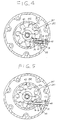
- Fig. 4 is a cross-sectional view of Fig. 1 taken along line 4-4 showing a first embodiment of the suction valve assembly stating one situation.
- Fig. 5 is a cross-sectionai view of Fig. 1 taken along line 4-4 a second embodiment of the suction valve assembly stating other situation.
- Fig. 1 depicts a fluid displacement apparatus in accordance with the present invention, in particular a slant-plate type compressor, according to one embodiment of the present invention.
- a compressor 10 comprises a cylindrical housing assembly 120 including a cylinder block 121, a front end plate 123 at one end of cylinder block 121, and a rear end plate 124 at the other end of cylinder block 121.
- a crank chamber 122 is formed between cylinder block 121 and front end plate 123, and front end plate 123 is mounted on the front end of cylinder block 121 (toward the left side of Fig. 1 ) by a plurality of bolts (not shown).
- Rear end plate 124 is mounted on cylinder block 121 at its rear end (towards the right in Fig. 1 ) by a plurality of bolts 102.
- a valve plate 125 is located between rear end plate 124 and cylinder block 121.
- An opening 231 is centrally formed in front end plate 123 for supporting drive shaft 126 by a first drive shaft bearing 130, which is disposed in opening 231.
- An inner end portion of drive shaft 126 is rotatably supported by a second drive shaft bearing 131 disposed within a center bore 210 formed in the cylinder block 121. Bore 210 extends rearward toward the end surface of cylinder block 121, wherein a valve control mechanism 119 is disposed.
- a cam rotor 140 is attached to drive shaft 126 by a pin member 261 and rotates together with drive shaft 126.
- a thrust needle bearing 132 is disposed between an inner end surface of front end plate 123 and adjacent axial end surface of cam rotor 140.
- Cam rotor 140 has an arm 141 with a pin member 142 extending therefrom.
- a slant plate 150 is adjacent cam rotor 140 and has an opening 153 through which drive shaft 126 passes.
- Slant plate 150 includes an arm 151 having a slot 152.
- Cam rotor 140 and slant plate 150 are coupled by pin member 142, which extends through slot 152 to create a hinged joint.
- Pin member 142 is slidable within slot 152 to allow adjustment of an angular position of a slant plate 150 with respect to a longitudinal axis of drive shaft 126.
- a wobble plate 160 is nutatably mounted on slant plate 150 through bearings 161 and 162.
- a fork-shaped slider 163 is attached to an outer peripheral end wobble plate 160 and slidably mounted on a sliding rail 164, which is held between front end plate 123 and cylinder block 121.
- Fork-shaped slider 163 prevents rotation of wobble plate 160.
- Wobble plate 160 nutates along rail 164 as cam rotor 140 rotates with drive shaft 126.
- Cylinder block 121 includes a plurality of peripherally-located cylinders 170, in which a plurality of corresponding pistons 171 reciprocate. Each piston 171 is connected to wobble plate 160 by a connecting rod 172.
- Rear end plate 124 has a centrally-located suction chamber 241 and a peripherally-located annular, discharge chamber 251.
- Valve plate 125 has a plurality of valved suction conduits 242 linking suction chamber 241 with the respective cylinders 170.
- Valve plate 125 also has a plurality of valved discharge conduits 252 linking discharge chamber 251 with the respective cylinders 170.
- Suction chamber 241 is connected to an evaporator (not shown) of a cooling circuit (not shown) by way of an inlet port 241a.
- Discharge chamber is provided with outlet port 251a, which is connected to a condenser (not shown) of the cooling circuit (not shown).
- First and second gaskets 127 and 128 are located between cylinder block 121 and an inner surface of valve plate 125 and between an outer surface of valve plate 125 and rear end plate 124, respectively, to seal the mating surfaces of cylinder block 121, valve plate 125, and rear end plate 124.
- a disc-shaped adjusting screw member 133 is disposed in a central region of bore 210 between beating 131 and valve control mechanism 119.
- Disc-shaped adjusting screw member 133 is screwed into bore 210 to be in contact with the inner end surface of drive shaft 126 through a washer 134 and adjusts an axial position of drive shaft 126 by the tightening or loosening screw member 133.
- Connecting rod 172 has first and second ball portions 173a and 173b formed at the front and rear ends, respectively, of rod 172. Piston 171 is connected to second ball portion 173b.
- second gasket 128 includes discharge valve 181 formed therein, which opens and closes discharge conduit 252, and valve retainer 180 formed therein for limiting the movement of discharge valve 181.
- first gasket 127 also includes suction valve 191 formed therein, which opens and closes suction conduit 242.
- a groove 190 is formed on a periphery of each cylinder 170 formed at the rear end of cylinder block 121 for restricting the opening motion of suction valve 191.
- suction valve mechanism 30 comprises a cover plate 43, which may be made of a steel or plastic resin, or the like, that is in contact with a first side surface of valve plate 125 and a supporting plate 44 slidably sandwiching cover plate 43 to valve plate 125.
- Cover plate 43 and supporting plate 44 have openings 43a and 44a, respectively, formed at central portions thereof, and are secured with together by coupling device, such as nut 80, so that axial movement of cover plate 43 and supporting plate 44 is limited.
- coupling device such as nut 80
- cover plate 43 has a core portion 43b formed at the center thereof and a plurality of projections 43c corresponding to a number of suction ports 242.
- a plurality of projections 43c are formed radially extending from the circumferential edge of circular shaped core projection 43b at equal intervals.
- Cover plate 43 includes notch portion 46 formed on a first end surface thereof and at least partially surrounding opening 43a.
- Supporting plate 44 includes cavity 44b formed therein and opened to notch portion 46.
- a ring spring 45 has a first end portion 45a extending in a radial direction and is disposed within notch portion 46, so that first end portion 45a is inserted into cavity 44b of supporting plate 44 and other end, portion 45b is in contact with an edge wall 46a of notch portion 46.
- cover plate 43 also has a pin portion 37 axially extending from a second end surface thereof.
- Rear end plate 124 contains a piston mechanism 35.
- Piston mechanism 35 includes a cylinder 39 oriented substantially perpendicular to the axis of drive shaft 126, a piston 38 disposed within cylinder 39, and a rod 36 extending from piston 38 toward suction chamber 241 and engaging pin portion 37.
- Piston 38 is preferably capable of reciprocating within cylinder 39.
- a first end of cylinder 39 is closed by a faucet 40.
- a coil spring 41 is disposed between a second end of cylinder 39 and piston 38 to urge piston 38 toward faucet 40.
- Cylinder 39 is in fluid communication with discharge chamber 251 through passage 42 formed therebetween in rear end plate 124.
- drive shaft 126 is rotated by the engine of the vehicle through electromagnetic clutch 300.
- Cam rotor 140 rotates together with drive shaft 126, thereby rotating slant plate 150, which causes wobble plate 160 to nutate.
- the nutational motion of wobble plate 160 reciprocates pistons 171 in their respective cylinders 170.
- refrigerant gas is introduced into suction chamber 241 through inlet port 241a.
- the gas then passes to cylinders 170 through suction valve mechanism 30 where it is compressed.
- the compressed refrigerant gas is discharged to discharge chamber 251 from each cylinder 170 through discharge conduits 252, and therefrom into the cooling circuit (not shown) through outlet port 251a.
- suction valve mechanism 30 The operation of suction valve mechanism 30 is now described in greater detail.
- cover plate 43 is at the position as shown in Fig. 4, such that a plurality of projections 43c cover open ends of suction ports 242, respectively, allowing a predetermined minimum opening, for example, about 10-30 percent of suction port 242 is opened to suction chamber 241.
- cover plate 43 may be designed to entirely cover the open ends of suction ports 242.
- regulaton of the extent, to which the area of the open ends of suction ports 242 is opened or closed is achieved by varying the cross-sectional area of cylinder 39; or the spring constant of springs 41 or 45, or both; the length of piston rod 36; or the location of piston rod 36.
- the pressure of discharge chamber 251 is relatively low at the time of starting the compressor.
- projection 43c only covers the open ends of suction ports 242 at predetermined minimum opening.
- a relatively small amount of refrigerant gas is introduced into cylinders 170 through suction conduit 242. Therefore, compressor 10 need not perform excessive compressive work at start-up, and refrigerant gas is gradually discharged to discharge chamber 251 from cylinder 170. As a result, torque shock of the compressor at the time of starting is reduced.
- suction ports 242 may be entirely opened to suction chamber 241 during ordinary operation of compressor 10. Thereby, fluid resistance of refrigerant gas at suction ports 242 may be reduced, and a relatively large amount of refrigerant gas may be introduced into cylinder 170 through suction port 242. Therefore, the compressor may obtain the high design volumetric efficiency.
- the present embodiment reduces the starting torque shock to the compressor while maintaining the high volumetric efficiency of the compressor.
Landscapes
- Engineering & Computer Science (AREA)
- Mechanical Engineering (AREA)
- General Engineering & Computer Science (AREA)
- Compressors, Vaccum Pumps And Other Relevant Systems (AREA)
- Compressor (AREA)
- Applications Or Details Of Rotary Compressors (AREA)
Applications Claiming Priority (2)
| Application Number | Priority Date | Filing Date | Title |
|---|---|---|---|
| JP346651/95 | 1995-12-13 | ||
| JP7346651A JPH09166075A (ja) | 1995-12-13 | 1995-12-13 | ピストン往復動式圧縮機 |
Publications (2)
| Publication Number | Publication Date |
|---|---|
| EP0779431A2 true EP0779431A2 (de) | 1997-06-18 |
| EP0779431A3 EP0779431A3 (de) | 1998-03-25 |
Family
ID=18384897
Family Applications (1)
| Application Number | Title | Priority Date | Filing Date |
|---|---|---|---|
| EP96308775A Withdrawn EP0779431A3 (de) | 1995-12-13 | 1996-12-04 | Ventilanordnung für einem Verdichter |
Country Status (5)
| Country | Link |
|---|---|
| US (1) | US5873706A (de) |
| EP (1) | EP0779431A3 (de) |
| JP (1) | JPH09166075A (de) |
| KR (1) | KR970045523A (de) |
| TW (1) | TW348201B (de) |
Cited By (1)
| Publication number | Priority date | Publication date | Assignee | Title |
|---|---|---|---|---|
| FR2938050A1 (fr) * | 2008-11-06 | 2010-05-07 | Valeo Systemes Thermiques | Boucle de climatisation comprenant une vanne en entree du compresseur |
Families Citing this family (7)
| Publication number | Priority date | Publication date | Assignee | Title |
|---|---|---|---|---|
| DE19710379C1 (de) * | 1997-03-13 | 1998-08-20 | Luk Fahrzeug Hydraulik | Sauggedrosselte Pumpe |
| JPH10281059A (ja) * | 1997-04-02 | 1998-10-20 | Sanden Corp | プーリー直結型容量可変型斜板式圧縮機 |
| JP2000016068A (ja) * | 1998-07-08 | 2000-01-18 | Sanden Corp | 温度自動膨張弁 |
| JP4034883B2 (ja) | 1998-07-08 | 2008-01-16 | サンデン株式会社 | 温度自動膨張弁 |
| JP4181274B2 (ja) * | 1998-08-24 | 2008-11-12 | サンデン株式会社 | 圧縮機 |
| US9062665B2 (en) | 2013-01-15 | 2015-06-23 | Husco International, Inc. | Hydraulic piston pump with throttle control |
| US11378074B2 (en) * | 2020-09-01 | 2022-07-05 | Zf Cv Systems Europe Bv | Discharge cut-off valve |
Citations (1)
| Publication number | Priority date | Publication date | Assignee | Title |
|---|---|---|---|---|
| US4976284A (en) | 1990-01-16 | 1990-12-11 | General Motors Corporation | Reed valve for piston machine |
Family Cites Families (15)
| Publication number | Priority date | Publication date | Assignee | Title |
|---|---|---|---|---|
| DE2357578A1 (de) * | 1973-11-19 | 1975-05-22 | Billstein Spezialfab Wilhelm | Regelbare zungenventileinrichtung fuer kolbenverdichter |
| US4011029A (en) * | 1974-05-17 | 1977-03-08 | Sankyo Electric Company Limited | Fluid suction and discharge apparatus |
| US4330999A (en) * | 1977-07-27 | 1982-05-25 | Kabushiki Kaisha Toyoda Jidoshokki Seisakusho | Refrigerant compressor |
| US4432698A (en) * | 1980-11-04 | 1984-02-21 | Tokico, Ltd. | Compressor having a starting load reducing apparatus |
| JPS5965582A (ja) * | 1982-10-08 | 1984-04-13 | Diesel Kiki Co Ltd | 多シリンダ式の可変容量圧縮機 |
| JPS59113279A (ja) * | 1982-12-20 | 1984-06-29 | Toyoda Autom Loom Works Ltd | 可変容量冷媒圧縮機 |
| DE3329790C2 (de) * | 1983-08-18 | 1995-11-30 | Wabco Gmbh | Ventilträger für Kolbenverdichter |
| AU615200B2 (en) * | 1987-06-30 | 1991-09-26 | Sanden Corporation | Refrigerant circuit with passageway control mechanism |
| JP2564225Y2 (ja) * | 1991-07-03 | 1998-03-04 | サンデン株式会社 | 多気筒型圧縮機 |
| JP3024315B2 (ja) * | 1991-10-16 | 2000-03-21 | 株式会社豊田自動織機製作所 | 可変容量圧縮機 |
| US5183395A (en) * | 1992-03-13 | 1993-02-02 | Vilter Manufacturing Corporation | Compressor slide valve control |
| JPH06147116A (ja) * | 1992-11-13 | 1994-05-27 | Toyota Autom Loom Works Ltd | ピストン型圧縮機 |
| WO1994028305A1 (en) * | 1993-05-21 | 1994-12-08 | Kabushiki Kaisha Toyoda Jidoshokki Seisakusho | Reciprocating type compressor |
| JPH07324678A (ja) * | 1994-05-31 | 1995-12-12 | Nippondenso Co Ltd | 斜板型圧縮機 |
| JP3505233B2 (ja) * | 1994-09-06 | 2004-03-08 | サンデン株式会社 | 圧縮機 |
-
1995
- 1995-12-13 JP JP7346651A patent/JPH09166075A/ja active Pending
-
1996
- 1996-12-04 EP EP96308775A patent/EP0779431A3/de not_active Withdrawn
- 1996-12-06 US US08/761,821 patent/US5873706A/en not_active Expired - Fee Related
- 1996-12-09 TW TW085115192A patent/TW348201B/zh active
- 1996-12-10 KR KR1019960063415A patent/KR970045523A/ko not_active Withdrawn
Patent Citations (1)
| Publication number | Priority date | Publication date | Assignee | Title |
|---|---|---|---|---|
| US4976284A (en) | 1990-01-16 | 1990-12-11 | General Motors Corporation | Reed valve for piston machine |
Cited By (1)
| Publication number | Priority date | Publication date | Assignee | Title |
|---|---|---|---|---|
| FR2938050A1 (fr) * | 2008-11-06 | 2010-05-07 | Valeo Systemes Thermiques | Boucle de climatisation comprenant une vanne en entree du compresseur |
Also Published As
| Publication number | Publication date |
|---|---|
| US5873706A (en) | 1999-02-23 |
| TW348201B (en) | 1998-12-21 |
| KR970045523A (ko) | 1997-07-26 |
| JPH09166075A (ja) | 1997-06-24 |
| EP0779431A3 (de) | 1998-03-25 |
Similar Documents
| Publication | Publication Date | Title |
|---|---|---|
| EP0340024B1 (de) | Schiefscheibenverdichter mit variablem Hubmechanismus | |
| US5765464A (en) | Reciprocating pistons of piston-type compressor | |
| CA1235402A (en) | Refrigerant compressor with a capacity adjusting mechanism | |
| EP0318316B1 (de) | Schiefscheibenverdichter mit Vorrichtung zur Hubveränderung | |
| US5632609A (en) | Valved discharge mechanism of a refrigerant compressor | |
| US5425303A (en) | Slant plate-type compressor with variable displacement mechanism | |
| US5533871A (en) | Single-headed-piston-type swash-plate compressor having pulsation damping system | |
| EP1368568A1 (de) | Axialkolbenverdichter mit taumelscheibenaktuator | |
| EP0547812B1 (de) | Schiefscheibenverdichter mit variablem Hubmechanismus | |
| US5688111A (en) | Valved suction mechanism of a refrigerant compressor | |
| US6336795B1 (en) | Fluid displacement apparatus with suction reed valve stopper | |
| EP0325168B1 (de) | Schiefscheibenverdichter mit Vorrichtung zur Hubänderung | |
| EP0437314A1 (de) | Auslassventil-Mechanismus eines Kühlverdichters | |
| US5873706A (en) | Valved suction mechanism for refrigerant compressor | |
| US6120259A (en) | Swash plate type compressor | |
| US5255569A (en) | Slant plate type compressor with variable displacement mechanism | |
| EP0499343B1 (de) | Taumelscheibenkompressor | |
| EP0844389B1 (de) | Schrägscheibenverdichter | |
| CA1326475C (en) | Slant plate type compressor with variable displacement mechanism | |
| US6224349B1 (en) | Reciprocating type compressor having orbiting valve plate |
Legal Events
| Date | Code | Title | Description |
|---|---|---|---|
| PUAI | Public reference made under article 153(3) epc to a published international application that has entered the european phase |
Free format text: ORIGINAL CODE: 0009012 |
|
| AK | Designated contracting states |
Kind code of ref document: A2 Designated state(s): DE FR GB IT SE |
|
| PUAL | Search report despatched |
Free format text: ORIGINAL CODE: 0009013 |
|
| AK | Designated contracting states |
Kind code of ref document: A3 Designated state(s): DE FR GB IT SE |
|
| 17P | Request for examination filed |
Effective date: 19980911 |
|
| 17Q | First examination report despatched |
Effective date: 20000105 |
|
| STAA | Information on the status of an ep patent application or granted ep patent |
Free format text: STATUS: THE APPLICATION IS DEEMED TO BE WITHDRAWN |
|
| 18D | Application deemed to be withdrawn |
Effective date: 20011220 |