EP0779476A2 - Regelklappe, insbesondere für Heissgase - Google Patents
Regelklappe, insbesondere für Heissgase Download PDFInfo
- Publication number
- EP0779476A2 EP0779476A2 EP96660096A EP96660096A EP0779476A2 EP 0779476 A2 EP0779476 A2 EP 0779476A2 EP 96660096 A EP96660096 A EP 96660096A EP 96660096 A EP96660096 A EP 96660096A EP 0779476 A2 EP0779476 A2 EP 0779476A2
- Authority
- EP
- European Patent Office
- Prior art keywords
- axle
- control damper
- flange
- component
- gap
- Prior art date
- Legal status (The legal status is an assumption and is not a legal conclusion. Google has not performed a legal analysis and makes no representation as to the accuracy of the status listed.)
- Withdrawn
Links
- 239000007789 gas Substances 0.000 title claims abstract description 4
- 238000003754 machining Methods 0.000 claims abstract description 13
- 238000009413 insulation Methods 0.000 claims abstract description 4
- 238000009423 ventilation Methods 0.000 claims description 2
- 238000010276 construction Methods 0.000 description 4
- UGFAIRIUMAVXCW-UHFFFAOYSA-N Carbon monoxide Chemical compound [O+]#[C-] UGFAIRIUMAVXCW-UHFFFAOYSA-N 0.000 description 1
- 238000010586 diagram Methods 0.000 description 1
- 239000006185 dispersion Substances 0.000 description 1
- 239000003546 flue gas Substances 0.000 description 1
- 238000000034 method Methods 0.000 description 1
- 230000000284 resting effect Effects 0.000 description 1
- 238000003466 welding Methods 0.000 description 1
Images

Classifications
-
- F—MECHANICAL ENGINEERING; LIGHTING; HEATING; WEAPONS; BLASTING
- F23—COMBUSTION APPARATUS; COMBUSTION PROCESSES
- F23L—SUPPLYING AIR OR NON-COMBUSTIBLE LIQUIDS OR GASES TO COMBUSTION APPARATUS IN GENERAL ; VALVES OR DAMPERS SPECIALLY ADAPTED FOR CONTROLLING AIR SUPPLY OR DRAUGHT IN COMBUSTION APPARATUS; INDUCING DRAUGHT IN COMBUSTION APPARATUS; TOPS FOR CHIMNEYS OR VENTILATING SHAFTS; TERMINALS FOR FLUES
- F23L13/00—Construction of valves or dampers for controlling air supply or draught
- F23L13/02—Construction of valves or dampers for controlling air supply or draught pivoted about a single axis but having not other movement
Definitions
- the object of the invention is a control damper, particularly for hot gases, which includes an insulated duct component and a blade component that rotates inside it on an axle, in which the axle is supported, at least on one side, by means of a support bearing placed outside the insulation.
- a problem in the aforementioned type of damper is the strong flow of heat along the axle, which heats the bearing unreasonably.
- the temperature of the flue gas is, for example 500 - 800°C, it is difficult to keep the bearing at a reasonable operating temperature (less than 150°C).
- the axle and the gaskets are cooled by means of an air current, such as that described in the French patent publication FR 2320548.
- the principal parts of the control damper are the duct component 2, which includes internal and external jackets 3 and 4, and the rotatable blade 2 supported by axle 7.
- the axle is rotated by means of rotating devices 9 and 10, in a manner that is, as such, known. Between the jacket components 3 and 4 there is thermal insulation 6, through which axle 7 is led.
- the bearing 9 is supported on an auxiliary structure resting on frame 1.
- the bearing 9 carries axle 7, the end of which is separated from the heat section by means of heat gap 8.
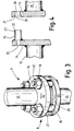
- FIG. 3 shows this heat gap in detail, in which axle 7 is shown by the first, hot axle 12, and its continuation axle 11. At the ends of these are flange components 13 and 14, which are set opposite one another, and which are kept at a distance from one another by collars 15. These collars are welded to the first component 14, while the securing proper takes place by means of bolted connections 16, 17. It is advantageous to use spring washers 19 under nuts 17, to even the compressive force.
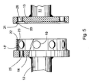
- Figure 4 shows the construction of the heat gap in greater detail, which is used to align the continuation axle 11 with the hot axle 12.
- the welded collars 15 of the first flange 14 are machined in the direction of the axle, i.e. axially, in which case the axial machining 22 is made precisely at right angles to the line of the axle.
- the ends of the collars 15 are machined for a short distance from a point touching a common circumference creating radial machining 23, which is precisely concentric with the first part 12 of the axle.
- Axial machining 20 is correspondingly formed in the flange 13 of the second component of axle 7, and is precisely at right angles to the continuation of the axle and correspondingly concentric with machining 21.
- the radial machining 21 and 23 correspond to one another with a suitable tolerance and determine the precise location of the continuation of the axle concentrically with the hot axle 12 and correspondingly end machining 20 and 22 align the axles precisely with one another. It is quite essential, that an undemanding level of precision of the axles, in engineering workshop terms, is sufficient.
- the precision of the location of continuation axle 11 is, in any event, considerably better that what could be achieved in, for example, a welded joint construction. The machining thus corrects the small faults that take place in the welding of the flanges and collars.
- the heat gap breaks the direct thermal conductivity of the first component 12 and offers a large heat dispersion surface between the flanges.
- the internal diameter of the collars 15 is 10 - 15 % larger than the external diameter of the bolts 16.
- the diameter of flanges 13, 14 is advantageously 250 - 300 % of the diameter of hot axle 12 and their thickness 20 - 35 % of the diameter of the hot axle 12.
- the total cross-sectional surface of the components should be minimized.
Landscapes
- Engineering & Computer Science (AREA)
- Chemical & Material Sciences (AREA)
- Combustion & Propulsion (AREA)
- Mechanical Engineering (AREA)
- General Engineering & Computer Science (AREA)
- Air-Flow Control Members (AREA)
- Lift Valve (AREA)
Applications Claiming Priority (2)
| Application Number | Priority Date | Filing Date | Title |
|---|---|---|---|
| FI950529U | 1995-12-15 | ||
| FI950529U FI2289U1 (fi) | 1995-12-15 | 1995-12-15 | Säätöpelti erityisesti kuumia kaasuja varten |
Publications (2)
| Publication Number | Publication Date |
|---|---|
| EP0779476A2 true EP0779476A2 (de) | 1997-06-18 |
| EP0779476A3 EP0779476A3 (de) | 1998-08-05 |
Family
ID=8542791
Family Applications (1)
| Application Number | Title | Priority Date | Filing Date |
|---|---|---|---|
| EP96660096A Withdrawn EP0779476A3 (de) | 1995-12-15 | 1996-12-12 | Regelklappe, insbesondere für Heissgase |
Country Status (2)
| Country | Link |
|---|---|
| EP (1) | EP0779476A3 (de) |
| FI (1) | FI2289U1 (de) |
Cited By (4)
| Publication number | Priority date | Publication date | Assignee | Title |
|---|---|---|---|---|
| EP0937872A3 (de) * | 1998-02-24 | 2003-05-07 | Sammet Dampers OY | Abgasleitungssystem in einem Mehrmotorsystem und eine Schliessklappe dafür |
| US20150168005A1 (en) * | 2013-12-18 | 2015-06-18 | Honeywell International Inc. | Hvac actuator with taping flange |
| WO2016097678A1 (en) * | 2014-12-19 | 2016-06-23 | Norgren Limited | Valve with bearing isolation |
| US10941960B2 (en) | 2013-12-18 | 2021-03-09 | Ademco Inc. | HVAC actuator with position indicator |
Citations (1)
| Publication number | Priority date | Publication date | Assignee | Title |
|---|---|---|---|---|
| FR2320548A1 (fr) | 1975-08-08 | 1977-03-04 | Secr Social Service Brit | Appareil et procede pour examiner des echantillons |
Family Cites Families (4)
| Publication number | Priority date | Publication date | Assignee | Title |
|---|---|---|---|---|
| FR2320458A1 (fr) * | 1975-08-08 | 1977-03-04 | Europ Turb Vapeur | Dispositif de refroidissement d'un joint |
| DE2801360A1 (de) * | 1978-01-13 | 1979-07-19 | Walter Dreizler Gmbh & Co Kg W | Abgas-drosseleinrichtung |
| DE2802038C2 (de) * | 1978-01-18 | 1982-06-16 | Lorenz 7208 Spaichingen Mattes | Absperrvorrichtung für Rauchabzugrohr |
| DE3217685A1 (de) * | 1982-05-11 | 1985-02-14 | Rische, Bernward, 8039 Puchheim | Waermeverschlussklappe typ back-o-spar zur energieeinsparung (oel und gas) durch waermebalance und neuentwickelter waermeentkopplung |
-
1995
- 1995-12-15 FI FI950529U patent/FI2289U1/fi active
-
1996
- 1996-12-12 EP EP96660096A patent/EP0779476A3/de not_active Withdrawn
Patent Citations (1)
| Publication number | Priority date | Publication date | Assignee | Title |
|---|---|---|---|---|
| FR2320548A1 (fr) | 1975-08-08 | 1977-03-04 | Secr Social Service Brit | Appareil et procede pour examiner des echantillons |
Cited By (6)
| Publication number | Priority date | Publication date | Assignee | Title |
|---|---|---|---|---|
| EP0937872A3 (de) * | 1998-02-24 | 2003-05-07 | Sammet Dampers OY | Abgasleitungssystem in einem Mehrmotorsystem und eine Schliessklappe dafür |
| US20150168005A1 (en) * | 2013-12-18 | 2015-06-18 | Honeywell International Inc. | Hvac actuator with taping flange |
| US9623523B2 (en) * | 2013-12-18 | 2017-04-18 | Honeywell International Inc. | HVAC actuator with taping flange |
| US10184681B2 (en) | 2013-12-18 | 2019-01-22 | Honeywell International Inc. | HVAC actuator |
| US10941960B2 (en) | 2013-12-18 | 2021-03-09 | Ademco Inc. | HVAC actuator with position indicator |
| WO2016097678A1 (en) * | 2014-12-19 | 2016-06-23 | Norgren Limited | Valve with bearing isolation |
Also Published As
| Publication number | Publication date |
|---|---|
| FIU950529U0 (fi) | 1995-12-15 |
| FI2289U1 (fi) | 1996-01-25 |
| EP0779476A3 (de) | 1998-08-05 |
Similar Documents
| Publication | Publication Date | Title |
|---|---|---|
| US5272869A (en) | Turbine frame | |
| US5328324A (en) | Aerofoil blade containment | |
| US6358001B1 (en) | Turbine frame assembly | |
| US4281941A (en) | Device for high thermal stress connection between a part made of a ceramic material and a part made of a metallic material | |
| US6428272B1 (en) | Bolted joint for rotor disks and method of reducing thermal gradients therein | |
| US6439841B1 (en) | Turbine frame assembly | |
| EP0562534B1 (de) | Luftspaltabdichtungsring für eine dynamoelektrische Maschine | |
| EP1331364B1 (de) | Elastische Verbindungsmuffe für ein Dienstrohr in einem Doppelmantellagergehäuse | |
| US4235846A (en) | Converter for exhaust gas with removable insert housings having monolithic catalyst therein | |
| US4201426A (en) | Bearing clamping assembly for a gas turbine engine | |
| US6807803B2 (en) | Gas turbine exhaust diffuser | |
| EP0815995A3 (de) | Verfahren zur Herstellung von zylindrischen Strukturen mit Kühlkanalen | |
| CN1003952B (zh) | 废气管道的固定装置 | |
| CA1062618A (en) | Single case low pressure turbine | |
| EP1867909B1 (de) | Rohrdurchdringungssystem | |
| JPS5831036Y2 (ja) | 内部で絶縁されたベロ−ズ構体 | |
| US3019035A (en) | Mounting mechanism for labyrinth seal disc | |
| GB2215406A (en) | Turbine clearance control duct arrangement | |
| KR100582607B1 (ko) | 가스 터어빈 팽창 조인트용 가요성 시일 | |
| EP0664416A1 (de) | Verbindungsmittel für Abgasrohre bei Brennkraftmaschinen | |
| CN1014341B (zh) | 具有进口套管振动抑制器的轴流式可压缩流体涡轮机 | |
| JP3125594B2 (ja) | 蒸気タービンの排気管 | |
| US4218186A (en) | Insulated hub arrangement for high temperature centrifugal fan | |
| GB2206682A (en) | A rotary regenerative heat exchanger | |
| EP0779476A3 (de) | Regelklappe, insbesondere für Heissgase |
Legal Events
| Date | Code | Title | Description |
|---|---|---|---|
| PUAI | Public reference made under article 153(3) epc to a published international application that has entered the european phase |
Free format text: ORIGINAL CODE: 0009012 |
|
| AK | Designated contracting states |
Kind code of ref document: A2 Designated state(s): DE ES FR GB SE |
|
| PUAL | Search report despatched |
Free format text: ORIGINAL CODE: 0009013 |
|
| AK | Designated contracting states |
Kind code of ref document: A3 Designated state(s): DE ES FR GB SE |
|
| 17P | Request for examination filed |
Effective date: 19990111 |
|
| STAA | Information on the status of an ep patent application or granted ep patent |
Free format text: STATUS: THE APPLICATION IS DEEMED TO BE WITHDRAWN |
|
| 18D | Application deemed to be withdrawn |
Effective date: 20010703 |