EP0779487A2 - Refroidisseur à trempe - Google Patents
Refroidisseur à trempe Download PDFInfo
- Publication number
- EP0779487A2 EP0779487A2 EP96810776A EP96810776A EP0779487A2 EP 0779487 A2 EP0779487 A2 EP 0779487A2 EP 96810776 A EP96810776 A EP 96810776A EP 96810776 A EP96810776 A EP 96810776A EP 0779487 A2 EP0779487 A2 EP 0779487A2
- Authority
- EP
- European Patent Office
- Prior art keywords
- gas
- quench cooler
- water
- jacket
- line
- Prior art date
- Legal status (The legal status is an assumption and is not a legal conclusion. Google has not performed a legal analysis and makes no representation as to the accuracy of the status listed.)
- Granted
Links
Images
Classifications
-
- F—MECHANICAL ENGINEERING; LIGHTING; HEATING; WEAPONS; BLASTING
- F02—COMBUSTION ENGINES; HOT-GAS OR COMBUSTION-PRODUCT ENGINE PLANTS
- F02C—GAS-TURBINE PLANTS; AIR INTAKES FOR JET-PROPULSION PLANTS; CONTROLLING FUEL SUPPLY IN AIR-BREATHING JET-PROPULSION PLANTS
- F02C7/00—Features, components parts, details or accessories, not provided for in, or of interest apart form groups F02C1/00 - F02C6/00; Air intakes for jet-propulsion plants
- F02C7/12—Cooling of plants
- F02C7/16—Cooling of plants characterised by cooling medium
- F02C7/18—Cooling of plants characterised by cooling medium the medium being gaseous, e.g. air
- F02C7/185—Cooling means for reducing the temperature of the cooling air or gas
-
- F—MECHANICAL ENGINEERING; LIGHTING; HEATING; WEAPONS; BLASTING
- F28—HEAT EXCHANGE IN GENERAL
- F28C—HEAT-EXCHANGE APPARATUS, NOT PROVIDED FOR IN ANOTHER SUBCLASS, IN WHICH THE HEAT-EXCHANGE MEDIA COME INTO DIRECT CONTACT WITHOUT CHEMICAL INTERACTION
- F28C3/00—Other direct-contact heat-exchange apparatus
- F28C3/06—Other direct-contact heat-exchange apparatus the heat-exchange media being a liquid and a gas or vapour
- F28C3/08—Other direct-contact heat-exchange apparatus the heat-exchange media being a liquid and a gas or vapour with change of state, e.g. absorption, evaporation, condensation
-
- F—MECHANICAL ENGINEERING; LIGHTING; HEATING; WEAPONS; BLASTING
- F05—INDEXING SCHEMES RELATING TO ENGINES OR PUMPS IN VARIOUS SUBCLASSES OF CLASSES F01-F04
- F05D—INDEXING SCHEME FOR ASPECTS RELATING TO NON-POSITIVE-DISPLACEMENT MACHINES OR ENGINES, GAS-TURBINES OR JET-PROPULSION PLANTS
- F05D2260/00—Function
- F05D2260/20—Heat transfer, e.g. cooling
- F05D2260/232—Heat transfer, e.g. cooling characterized by the cooling medium
- F05D2260/2322—Heat transfer, e.g. cooling characterized by the cooling medium steam
Definitions
- the invention relates to a quench cooler for cooling a hot flowing gas, consisting essentially of a cylindrical jacket which is connected to a hot gas line via a gas inlet connection and to a cold gas line via a gas outlet connection, and which means for injecting water having. It also relates to the use of such a quench cooler in an open gas turbine plant.
- the object of the invention is therefore to create a quench cooler with a high degree of utilization for high gas and liquid temperatures and high pressures.
- the special thermohydraulic requirements for this class of apparatus provided they are used in modern gas turbine systems, are as follows: high gas inlet temperature between 300-530 ° C, high pressure on the gas side between 20 and 35 bar, low gas and liquid pressure losses and relatively high cooling span of the gas greater than 250 ° C.
- this object is achieved in that a packed column which fills the cross section of the jacket through which the flow is through is arranged downstream of the water injection means. It is particularly favorable if the packed column is designed as a cartridge which can be inserted into the cylindrical jacket and has its own jacket.
- the advantage of this measure can be seen in particular in the compact, maintenance-friendly design of the apparatus. This is particularly important because space requirements can play a decisive role in both installation and maintenance.
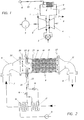
- FIG. 1 is compressed in the gas turbine cycle with 1 atmospheric fresh air drawn in a compressor 2 to the working pressure.
- the compressed air is strongly heated in a combustion chamber 3 fired with natural gas, for example; the resulting fuel gas is expanded in a gas turbine 4 while performing work.
- the energy obtained in this way is delivered to a generator 5 or the compressor 2.
- the exhaust gases from the gas turbine are passed outside via the exhaust line 6 and a chimney, not shown.
- an air line 7 branches off from the outlet of the compressor 2 to a quench cooler 8. After flowing through it, the cooled air reaches the various consumers via a cooling line 9. On the water side, the quench cooler is fed via line 22 with a water pump 15.
- the medium to be cooled enters the apparatus via the hot gas line 7 - here the air line from the compressor.
- the apparatus essentially consists of the gas inlet connection 11, which is flanged to the air line 7 on the one hand and is connected to the cylindrical jacket 10 on the other hand via a flange.
- this jacket 10 is in turn connected via a flange to the gas outlet connector 12, which is also flanged to the cold gas line 9 - here the cooling line.
- the water injection means are arranged distributed over the circular cross section. These are a plurality of pressure atomizing nozzles 30. They are fed with water on the one hand from an annular chamber 20 surrounding the apparatus, and on the other hand with steam from an annular chamber 21 surrounding the apparatus. The steam serves to atomize the water, droplets in microns at the nozzle outlet -Size can be achieved.
- the steam treatment for the water atomization in the water injection means 30 expediently takes place in the hot gas line, here in the air line 7, which leads from the compressor to the quench cooler 8.
- the working medium first reaches a water preheater 16.
- the major part of the water is conducted via the water line 22 to the annular chamber 20.
- a control valve 18 is arranged in this water line 22.
- part of the water is branched off and led into the water evaporator 17.
- This water evaporator is connected upstream of the preheater in the hot gas line.
- the generated steam passes from the evaporator via a steam line 23, in which a pressure-maintaining valve 19 is arranged, into the annular chamber 21.
- the flow-through circular cross section of the jacket 10 is provided with a static mixer in the form of a packed column 13.
- a static mixer in the form of a packed column 13.
- packing can be a filling, i.e. a so-called random packing.
- An orderly filling is more suitable, which offers the advantages of a higher mixing performance with a lower pressure drop through homogeneously targeted distribution.
- Stainless steel or ceramic can be used as material for such packs known per se, all of which are characterized by good wettability in aqueous systems.
- the injected water and air flow through the several layers of the regular pack in cocurrent.
- the two phases are completely mixed in the package, the water content evaporating.
- the hot air supplies the enthalpy of vaporization so that the air temperature in the apparatus is reduced isenthalpically.
- the entry state of the air to be cooled is approx. 34 bar and approx. 500 ° C; the air volume is approx. 35 kg / sec. The amount of water injected is approx. 10 kg / s.
- the working medium then leaves the apparatus as cooling air at a temperature of approximately 170 ° C. via the air outlet connection 12. In the present In this case, the air is cooled down by 330 ° C.
- Such an apparatus is characterized by a compact design and works without significant pressure losses.
- the compactness and the short lines required only allow the quench cooler to be installed in the immediate vicinity of the machine, so that it can be advantageously included in the sound insulation of the thermal block.
- the power of the gas turbine is increased in that the mass flow acting on the gas turbine is at least partially increased by the evaporated water fraction; After performing its cooling function, the coolant is used for work in the gas turbine blading.
- the packing is held in the column in its own casing 14 in the form of a thin sheet and is thus designed as a cartridge which can be inserted into the cylindrical casing 10.
- This has the advantage that evaporation residues cannot deposit on the actual apparatus jacket 10.
- the column is removed for maintenance, the evaporation residues that form a layer thus remain inside the cartridge. The risk of particles breaking off from the jacket wall 10 and their possible transport into the consumers to be cooled is thus eliminated.
- a cooling air flow leading into the hot part of the gas turbine must not contain any water droplets, since these can cause damage when they hit the hot parts. If water is found in the cooling air flow, the machine must be shut down.
- Water detection means for the present high pressure and temperature conditions in modern gas turbines are not currently available on the market.
- the remedy here is a temperature measurement in static Mixer itself, for which purpose a plurality of appropriately switched thermocouples 25 are arranged inside the package. Just as water hits the walls of the packing, their temperature drops quickly. If the water flow is large enough, the temperature of the pack will drop to the wet steam temperature. Such a measurement is therefore suitable for detecting water hitting the packing in a very short time.
- thermocouples 26 and 27 are passed through the jacket 10 in a suitable manner and appropriately distributed in the cross-section through which they flow. Detecting a temperature difference between the mixer inlet and outlet indicates proper evaporation.
- any condensate accumulating in the quench cooler is introduced via a drain line 24 into the exhaust line 6 leading to the chimney.
- the usual flash boxes can be dispensed with, in which the pressurized condensate is expanded to atmospheric pressure and cooled down by mixing with cold water.
- the invention is of course not limited to the exemplary embodiment shown and described.
- the new apparatus concept can basically be used in all processes in which the work equipment involved has high temperatures and even high pressures.
Landscapes
- Engineering & Computer Science (AREA)
- Chemical & Material Sciences (AREA)
- Combustion & Propulsion (AREA)
- Mechanical Engineering (AREA)
- General Engineering & Computer Science (AREA)
- Turbine Rotor Nozzle Sealing (AREA)
- Physical Or Chemical Processes And Apparatus (AREA)
- Heat-Exchange Devices With Radiators And Conduit Assemblies (AREA)
Applications Claiming Priority (2)
| Application Number | Priority Date | Filing Date | Title |
|---|---|---|---|
| DE19546726A DE19546726A1 (de) | 1995-12-14 | 1995-12-14 | Quench-Kühler |
| DE19546726 | 1995-12-14 |
Publications (3)
| Publication Number | Publication Date |
|---|---|
| EP0779487A2 true EP0779487A2 (fr) | 1997-06-18 |
| EP0779487A3 EP0779487A3 (fr) | 1998-11-25 |
| EP0779487B1 EP0779487B1 (fr) | 2001-03-28 |
Family
ID=7780142
Family Applications (1)
| Application Number | Title | Priority Date | Filing Date |
|---|---|---|---|
| EP96810776A Expired - Lifetime EP0779487B1 (fr) | 1995-12-14 | 1996-11-12 | Refroidisseur à trempe |
Country Status (4)
| Country | Link |
|---|---|
| US (1) | US5839271A (fr) |
| EP (1) | EP0779487B1 (fr) |
| JP (1) | JPH09178369A (fr) |
| DE (2) | DE19546726A1 (fr) |
Families Citing this family (12)
| Publication number | Priority date | Publication date | Assignee | Title |
|---|---|---|---|---|
| DE10027842A1 (de) * | 2000-06-05 | 2001-12-20 | Alstom Power Nv | Verfahren zum Kühlen einer Gasturbinenanlage sowie Gasturbinenanlage zur Durchführung des Verfahrens |
| DE10234119A1 (de) * | 2002-07-26 | 2004-02-05 | Linde Ag | Verfahren und Vorrichtung zum Abkühlen eines einer Gasturbine zuzuführenden Luftstromes |
| AU2003299245A1 (en) * | 2002-12-17 | 2004-07-09 | Hydrogensource Llc | Evaporator |
| JP4100316B2 (ja) | 2003-09-30 | 2008-06-11 | 株式会社日立製作所 | ガスタービン設備 |
| US7491263B2 (en) | 2004-04-05 | 2009-02-17 | Technology Innovation, Llc | Storage assembly |
| DE102015004735A1 (de) | 2015-04-11 | 2016-10-13 | Fritz Curtius | Quench-Kühler zur Aufheizung von Wasser |
| CN106017130A (zh) * | 2016-06-27 | 2016-10-12 | 广西农垦糖业集团红河制糖有限公司 | 喷射式热水冷却装置 |
| CN107131772B (zh) * | 2017-06-27 | 2022-10-21 | 江苏正丹化学工业股份有限公司 | 一种乙烯基甲苯生产过程中的急冷器 |
| US20190309685A1 (en) * | 2018-04-05 | 2019-10-10 | United Technologies Corporation | Fluid injection cooling |
| US10677767B2 (en) * | 2018-06-12 | 2020-06-09 | Vuv Analytics, Inc. | Vacuum ultraviolet absorption spectroscopy system and method |
| EP3599440A1 (fr) * | 2018-07-24 | 2020-01-29 | Siemens Aktiengesellschaft | Procédé et dispositif de génération d'un gaz |
| CN114396803B (zh) * | 2021-12-30 | 2025-08-26 | 拉普拉斯新能源科技股份有限公司 | 一种高温气体快速降温装置 |
Family Cites Families (16)
| Publication number | Priority date | Publication date | Assignee | Title |
|---|---|---|---|---|
| US2838135A (en) * | 1954-01-26 | 1958-06-10 | Pilo Claes Wilhelm | Process for the recovery of heat from hot gases |
| US3686830A (en) * | 1970-08-03 | 1972-08-29 | Richard L Huntington | Multiple compartment cross flow absorber |
| DE7104981U (de) * | 1971-02-10 | 1971-07-29 | Kunststofftechnik Gmbh U Co Kg | Nassabscheider fuer luftreinigungsanlage |
| GB1360628A (en) * | 1972-07-07 | 1974-07-17 | Decafix Ltd | Gas cooling |
| US3842615A (en) * | 1972-11-06 | 1974-10-22 | Standard Havens | Evaporative cooler |
| EP0060267A1 (fr) * | 1980-09-10 | 1982-09-22 | Foster-Miller Associates, Inc. | Refroidisseur a eau pulverisee |
| US4537023A (en) * | 1981-12-10 | 1985-08-27 | Mitsubishi Gas Chemical Company, Inc. | Regenerative gas turbine cycle |
| JPS59160032A (ja) * | 1983-03-01 | 1984-09-10 | Agency Of Ind Science & Technol | ガスタ−ビン |
| US4672820A (en) * | 1986-03-17 | 1987-06-16 | Goettl Adam D | Evaporative cooler pad assembly |
| DE8900464U1 (de) * | 1989-01-17 | 1989-03-16 | Bochumer Maschinenfabrik Arthur Schneider GmbH & Co KG, 4630 Bochum | Dampfkühleinrichtung |
| US4991391A (en) * | 1989-01-27 | 1991-02-12 | Westinghouse Electric Corp. | System for cooling in a gas turbine |
| US5160096A (en) * | 1991-10-11 | 1992-11-03 | United Technologies Corporation | Gas turbine cycle |
| DE4142375A1 (de) * | 1991-12-20 | 1993-07-08 | Siemens Ag | Kuehlluftkuehler fuer gasturbinen |
| GB9208647D0 (en) * | 1992-04-22 | 1992-06-10 | Boc Group Plc | Air separation |
| EP1064980B1 (fr) * | 1993-10-06 | 2003-02-12 | The Kansai Electric Power Co., Inc. | Procédé pour éliminer le dioxide de carbone de gaz de combustion |
| US5579631A (en) * | 1994-04-28 | 1996-12-03 | Westinghouse Electric Corporation | Steam cooling of gas turbine with backup air cooling |
-
1995
- 1995-12-14 DE DE19546726A patent/DE19546726A1/de not_active Withdrawn
-
1996
- 1996-11-12 DE DE59606667T patent/DE59606667D1/de not_active Expired - Fee Related
- 1996-11-12 EP EP96810776A patent/EP0779487B1/fr not_active Expired - Lifetime
- 1996-11-18 US US08/751,719 patent/US5839271A/en not_active Expired - Fee Related
- 1996-12-11 JP JP8330931A patent/JPH09178369A/ja active Pending
Non-Patent Citations (1)
| Title |
|---|
| None |
Also Published As
| Publication number | Publication date |
|---|---|
| US5839271A (en) | 1998-11-24 |
| DE19546726A1 (de) | 1997-06-19 |
| EP0779487A3 (fr) | 1998-11-25 |
| DE59606667D1 (de) | 2001-05-03 |
| JPH09178369A (ja) | 1997-07-11 |
| EP0779487B1 (fr) | 2001-03-28 |
Similar Documents
| Publication | Publication Date | Title |
|---|---|---|
| EP0779423A2 (fr) | Refroidisseur à trempe | |
| DE69635318T2 (de) | Injektionsvorrichtung für tröpfchenförmige Flüssigkeit | |
| DE102012011294B4 (de) | Verfahren zum Kühlen einer Gasturbinenanlage sowie Gasturbinenanlage zur Durchführung des Verfahrens | |
| EP0566868B1 (fr) | Procédé pour utilisation d'une installation pour turbine à gaz | |
| EP1682750B1 (fr) | Centrale electrique | |
| EP0779487B1 (fr) | Refroidisseur à trempe | |
| EP0602040A1 (fr) | Refroidissement d'une turbine a vapeur basse pression en mode ventilation. | |
| DE2035488A1 (de) | Verfahren und Vorrichtung zum Ver dampfen von flussigem Erdgas | |
| EP1704313A1 (fr) | Procede pour faire fonctionner une centrale electrique | |
| CH701545A2 (de) | System und Verfahren zum Liefern von Brennstoff an eine Gasturbine. | |
| DE2235125C3 (fr) | ||
| DE2163096A1 (de) | Verfahren und vorrichtung zur aufheizung eines gasstromes, der durch vergasung von kohle bzw. kohlenstaub gewonnen wird | |
| DE10230610A1 (de) | Verfahren und Vorrichtung zur Verhinderung von Ablagerungen in Dampfsystemen | |
| DE19808119C2 (de) | Wasserstoffverbrennungsturbinenanlage | |
| EP0924406A1 (fr) | Turbine à gaz avec un générateur de vapeur et un récupérateur disposés en parallèle dans les gaz d'échappement | |
| DE2630456A1 (de) | Brennkraftmaschine | |
| EP0476449A2 (fr) | Procédé et dispositif pour le séchage du gaz naturel et pour le recyclage du solvant de l'eau utilisé en cela | |
| DE19638573A1 (de) | Quench-Kühler | |
| EP0425941A1 (fr) | Dispositif de dégazage et de chauffage d'eau | |
| EP0919707A1 (fr) | Refroidisseur à air froid pour turbines à gaz | |
| DE1667613A1 (de) | Verfahren und Vorrichtung zur Herstellung von Inertgas | |
| DE2442054C3 (de) | Kühlturm | |
| DE958441C (de) | Arbeitsverfahren fuer den Waermeaustausch des Arbeitsmittels von Heissluft- bzw. Gasturbinen-Anlagen sowie Vorrichtung zur Ausuebung des Verfahrens | |
| DE1601654B2 (de) | Vorrichtung zum schutz einer mindestens zweiwelligen geschlos senen gasturbinenanlage | |
| EP0903483A1 (fr) | Procédé et dispositif pour le refroidissement d'un courant gazeux dans une turbine à gaz |
Legal Events
| Date | Code | Title | Description |
|---|---|---|---|
| PUAI | Public reference made under article 153(3) epc to a published international application that has entered the european phase |
Free format text: ORIGINAL CODE: 0009012 |
|
| AK | Designated contracting states |
Kind code of ref document: A2 Designated state(s): DE GB NL |
|
| PUAL | Search report despatched |
Free format text: ORIGINAL CODE: 0009013 |
|
| AK | Designated contracting states |
Kind code of ref document: A3 Designated state(s): DE GB NL |
|
| 17P | Request for examination filed |
Effective date: 19990503 |
|
| GRAG | Despatch of communication of intention to grant |
Free format text: ORIGINAL CODE: EPIDOS AGRA |
|
| 17Q | First examination report despatched |
Effective date: 20000621 |
|
| GRAG | Despatch of communication of intention to grant |
Free format text: ORIGINAL CODE: EPIDOS AGRA |
|
| GRAH | Despatch of communication of intention to grant a patent |
Free format text: ORIGINAL CODE: EPIDOS IGRA |
|
| GRAH | Despatch of communication of intention to grant a patent |
Free format text: ORIGINAL CODE: EPIDOS IGRA |
|
| GRAA | (expected) grant |
Free format text: ORIGINAL CODE: 0009210 |
|
| AK | Designated contracting states |
Kind code of ref document: B1 Designated state(s): DE GB NL |
|
| PG25 | Lapsed in a contracting state [announced via postgrant information from national office to epo] |
Ref country code: NL Free format text: LAPSE BECAUSE OF FAILURE TO SUBMIT A TRANSLATION OF THE DESCRIPTION OR TO PAY THE FEE WITHIN THE PRESCRIBED TIME-LIMIT Effective date: 20010328 Ref country code: GB Free format text: LAPSE BECAUSE OF FAILURE TO SUBMIT A TRANSLATION OF THE DESCRIPTION OR TO PAY THE FEE WITHIN THE PRESCRIBED TIME-LIMIT Effective date: 20010328 |
|
| REF | Corresponds to: |
Ref document number: 59606667 Country of ref document: DE Date of ref document: 20010503 |
|
| EN | Fr: translation not filed | ||
| NLV1 | Nl: lapsed or annulled due to failure to fulfill the requirements of art. 29p and 29m of the patents act | ||
| GBV | Gb: ep patent (uk) treated as always having been void in accordance with gb section 77(7)/1977 [no translation filed] |
Effective date: 20010328 |
|
| PLBE | No opposition filed within time limit |
Free format text: ORIGINAL CODE: 0009261 |
|
| STAA | Information on the status of an ep patent application or granted ep patent |
Free format text: STATUS: NO OPPOSITION FILED WITHIN TIME LIMIT |
|
| 26N | No opposition filed | ||
| PGFP | Annual fee paid to national office [announced via postgrant information from national office to epo] |
Ref country code: DE Payment date: 20051110 Year of fee payment: 10 |
|
| PG25 | Lapsed in a contracting state [announced via postgrant information from national office to epo] |
Ref country code: DE Free format text: LAPSE BECAUSE OF NON-PAYMENT OF DUE FEES Effective date: 20070601 |