EP0779531A2 - Dispositif d'affichage stéréoscopique - Google Patents
Dispositif d'affichage stéréoscopique Download PDFInfo
- Publication number
- EP0779531A2 EP0779531A2 EP96119334A EP96119334A EP0779531A2 EP 0779531 A2 EP0779531 A2 EP 0779531A2 EP 96119334 A EP96119334 A EP 96119334A EP 96119334 A EP96119334 A EP 96119334A EP 0779531 A2 EP0779531 A2 EP 0779531A2
- Authority
- EP
- European Patent Office
- Prior art keywords
- display
- stereoscopic display
- barrier
- moving
- display system
- Prior art date
- Legal status (The legal status is an assumption and is not a legal conclusion. Google has not performed a legal analysis and makes no representation as to the accuracy of the status listed.)
- Granted
Links
- 230000004888 barrier function Effects 0.000 claims abstract description 125
- 239000004973 liquid crystal related substance Substances 0.000 claims description 17
- 230000010287 polarization Effects 0.000 claims description 12
- 239000013078 crystal Substances 0.000 claims 1
- 230000000694 effects Effects 0.000 abstract description 6
- 206010047571 Visual impairment Diseases 0.000 description 3
- 239000011521 glass Substances 0.000 description 3
- 230000001360 synchronised effect Effects 0.000 description 3
- 230000000903 blocking effect Effects 0.000 description 1
- 238000010276 construction Methods 0.000 description 1
- 230000008602 contraction Effects 0.000 description 1
- 230000003247 decreasing effect Effects 0.000 description 1
- 230000001419 dependent effect Effects 0.000 description 1
Images


Classifications
-
- H—ELECTRICITY
- H04—ELECTRIC COMMUNICATION TECHNIQUE
- H04N—PICTORIAL COMMUNICATION, e.g. TELEVISION
- H04N13/00—Stereoscopic video systems; Multi-view video systems; Details thereof
- H04N13/30—Image reproducers
- H04N13/366—Image reproducers using viewer tracking
- H04N13/376—Image reproducers using viewer tracking for tracking left-right translational head movements, i.e. lateral movements
-
- G—PHYSICS
- G02—OPTICS
- G02B—OPTICAL ELEMENTS, SYSTEMS OR APPARATUS
- G02B30/00—Optical systems or apparatus for producing three-dimensional [3D] effects, e.g. stereoscopic images
- G02B30/20—Optical systems or apparatus for producing three-dimensional [3D] effects, e.g. stereoscopic images by providing first and second parallax images to an observer's left and right eyes
- G02B30/22—Optical systems or apparatus for producing three-dimensional [3D] effects, e.g. stereoscopic images by providing first and second parallax images to an observer's left and right eyes of the stereoscopic type
- G02B30/25—Optical systems or apparatus for producing three-dimensional [3D] effects, e.g. stereoscopic images by providing first and second parallax images to an observer's left and right eyes of the stereoscopic type using polarisation techniques
-
- G—PHYSICS
- G02—OPTICS
- G02B—OPTICAL ELEMENTS, SYSTEMS OR APPARATUS
- G02B30/00—Optical systems or apparatus for producing three-dimensional [3D] effects, e.g. stereoscopic images
- G02B30/20—Optical systems or apparatus for producing three-dimensional [3D] effects, e.g. stereoscopic images by providing first and second parallax images to an observer's left and right eyes
- G02B30/26—Optical systems or apparatus for producing three-dimensional [3D] effects, e.g. stereoscopic images by providing first and second parallax images to an observer's left and right eyes of the autostereoscopic type
- G02B30/27—Optical systems or apparatus for producing three-dimensional [3D] effects, e.g. stereoscopic images by providing first and second parallax images to an observer's left and right eyes of the autostereoscopic type involving lenticular arrays
-
- G—PHYSICS
- G02—OPTICS
- G02B—OPTICAL ELEMENTS, SYSTEMS OR APPARATUS
- G02B30/00—Optical systems or apparatus for producing three-dimensional [3D] effects, e.g. stereoscopic images
- G02B30/20—Optical systems or apparatus for producing three-dimensional [3D] effects, e.g. stereoscopic images by providing first and second parallax images to an observer's left and right eyes
- G02B30/26—Optical systems or apparatus for producing three-dimensional [3D] effects, e.g. stereoscopic images by providing first and second parallax images to an observer's left and right eyes of the autostereoscopic type
- G02B30/30—Optical systems or apparatus for producing three-dimensional [3D] effects, e.g. stereoscopic images by providing first and second parallax images to an observer's left and right eyes of the autostereoscopic type involving parallax barriers
- G02B30/31—Optical systems or apparatus for producing three-dimensional [3D] effects, e.g. stereoscopic images by providing first and second parallax images to an observer's left and right eyes of the autostereoscopic type involving parallax barriers involving active parallax barriers
-
- G—PHYSICS
- G02—OPTICS
- G02B—OPTICAL ELEMENTS, SYSTEMS OR APPARATUS
- G02B30/00—Optical systems or apparatus for producing three-dimensional [3D] effects, e.g. stereoscopic images
- G02B30/20—Optical systems or apparatus for producing three-dimensional [3D] effects, e.g. stereoscopic images by providing first and second parallax images to an observer's left and right eyes
- G02B30/26—Optical systems or apparatus for producing three-dimensional [3D] effects, e.g. stereoscopic images by providing first and second parallax images to an observer's left and right eyes of the autostereoscopic type
- G02B30/30—Optical systems or apparatus for producing three-dimensional [3D] effects, e.g. stereoscopic images by providing first and second parallax images to an observer's left and right eyes of the autostereoscopic type involving parallax barriers
- G02B30/32—Optical systems or apparatus for producing three-dimensional [3D] effects, e.g. stereoscopic images by providing first and second parallax images to an observer's left and right eyes of the autostereoscopic type involving parallax barriers characterised by the geometry of the parallax barriers, e.g. staggered barriers, slanted parallax arrays or parallax arrays of varying shape or size
-
- H—ELECTRICITY
- H04—ELECTRIC COMMUNICATION TECHNIQUE
- H04N—PICTORIAL COMMUNICATION, e.g. TELEVISION
- H04N13/00—Stereoscopic video systems; Multi-view video systems; Details thereof
- H04N13/30—Image reproducers
- H04N13/302—Image reproducers for viewing without the aid of special glasses, i.e. using autostereoscopic displays
- H04N13/31—Image reproducers for viewing without the aid of special glasses, i.e. using autostereoscopic displays using parallax barriers
-
- H—ELECTRICITY
- H04—ELECTRIC COMMUNICATION TECHNIQUE
- H04N—PICTORIAL COMMUNICATION, e.g. TELEVISION
- H04N13/00—Stereoscopic video systems; Multi-view video systems; Details thereof
- H04N13/30—Image reproducers
- H04N13/366—Image reproducers using viewer tracking
- H04N13/373—Image reproducers using viewer tracking for tracking forward-backward translational head movements, i.e. longitudinal movements
-
- H—ELECTRICITY
- H04—ELECTRIC COMMUNICATION TECHNIQUE
- H04N—PICTORIAL COMMUNICATION, e.g. TELEVISION
- H04N13/00—Stereoscopic video systems; Multi-view video systems; Details thereof
- H04N13/30—Image reproducers
- H04N13/398—Synchronisation thereof; Control thereof
-
- H—ELECTRICITY
- H04—ELECTRIC COMMUNICATION TECHNIQUE
- H04N—PICTORIAL COMMUNICATION, e.g. TELEVISION
- H04N13/00—Stereoscopic video systems; Multi-view video systems; Details thereof
- H04N13/30—Image reproducers
- H04N13/302—Image reproducers for viewing without the aid of special glasses, i.e. using autostereoscopic displays
- H04N13/305—Image reproducers for viewing without the aid of special glasses, i.e. using autostereoscopic displays using lenticular lenses, e.g. arrangements of cylindrical lenses
-
- H—ELECTRICITY
- H04—ELECTRIC COMMUNICATION TECHNIQUE
- H04N—PICTORIAL COMMUNICATION, e.g. TELEVISION
- H04N13/00—Stereoscopic video systems; Multi-view video systems; Details thereof
- H04N13/30—Image reproducers
- H04N13/332—Displays for viewing with the aid of special glasses or head-mounted displays [HMD]
- H04N13/334—Displays for viewing with the aid of special glasses or head-mounted displays [HMD] using spectral multiplexing
-
- H—ELECTRICITY
- H04—ELECTRIC COMMUNICATION TECHNIQUE
- H04N—PICTORIAL COMMUNICATION, e.g. TELEVISION
- H04N13/00—Stereoscopic video systems; Multi-view video systems; Details thereof
- H04N13/30—Image reproducers
- H04N13/332—Displays for viewing with the aid of special glasses or head-mounted displays [HMD]
- H04N13/337—Displays for viewing with the aid of special glasses or head-mounted displays [HMD] using polarisation multiplexing
-
- H—ELECTRICITY
- H04—ELECTRIC COMMUNICATION TECHNIQUE
- H04N—PICTORIAL COMMUNICATION, e.g. TELEVISION
- H04N13/00—Stereoscopic video systems; Multi-view video systems; Details thereof
- H04N13/30—Image reproducers
- H04N13/332—Displays for viewing with the aid of special glasses or head-mounted displays [HMD]
- H04N13/341—Displays for viewing with the aid of special glasses or head-mounted displays [HMD] using temporal multiplexing
Definitions
- the invention relates to a stereoscopic display system, which generates the impression of a stereoscopic image by binocular parallax.
- a stereoscopic display system uses a display comprising a pixel plane, wherein right and left images are depicted either alternating for the whole screen or alternating between adjacent pixels.
- Known stereoscopic display systems use special glasses, for example red and blue filter glasses, LCD shutter goggles or polarizing filter glasses.
- Other known prior stereoscopic displays use a parallax barrier with a fixed slit pitch or use a lenticular lens sheet. All these known stereoscopic display systems have the disadvantages that they show pseudoscopic images in the outer areas of the viewing area and/or that the viewing position is fixed due to the fixed geometry of the system.
- a first embodiment of the stereoscopic display system has a display comprising a pixel plane for alternating displaying right and left images and a parallax barrier made of barrier strips, which are arranged in front of the display, wherein the distance or pitch between adjacent barrier strips is variable. Therefore it is possible to vary the viewing position, which is a function of the distance.
- the barrier strips can be realised by any light blocking elements, like e.g. liquid crystal display elements or by mechanical elements.
- the variation of the distance can be done by a pantograph, wherein each barrier strip is connected to the pantograph.
- each barrier strip is connected to each joint-pivot of the pantograph, wherein one joint-pivot of the pantograph can be fixed in space, so that the position of the pantograph relativ to the display is fixed.
- the movement of the pantograph can be accomplished by a moving rod mechanism connected to the pantograph, which is controlled by a controller.
- each barrier strip is rotatable, so that the angle between the barriers and the display panel can be varied.
- a barrier width which results by the projection of the barriers onto the display panel can be adjusted in addition to the distance between said barriers.
- the rotation of the barriers can be performed by a rack and pinion mechanism.
- the rack can be moved linearly.
- the stereoscopic display system is further provided with a controller for controlling a moving-rack mechanism. It is further possible that the pantograph is controlled on both ends by a moving-rod mechanism.
- adjacent pixels of the pixel plane alternate between left and right images.
- a stereoscopic display system includes a display comprising a pixel plane for displaying right and left images, the system further comprises moving barriers arranged in front of the display to line between right and left eye, wherein the barriers are set in a first mode to a first angle, which directs the right image to the right eye when a right image is depicted, and is set in a second mode to a second angle, which directs the left image to the left eye when a left image is depicted on the display.
- the barrier of the stereoscopic display system is set on the display essentially perpendicular, i.e. in an intermediate position the angle between the barriers and the surface of the display is approximately 90°.
- the switching between left and right viewing directions is fast enough so that the impression of a continuous image is generated because of the afterimage property of the human eye.
- the barriers of the stereoscopic display are connected to a switching means which switches the barriers between left and right image viewing positions.
- a switching means can be formed by a joint arm.
- the stereoscopic display system further comprises a moving barrier controller and a display controller to switch between left and right images, both of which are controlled by a common timing signal.
- the switching means of the stereoscopic display system comprises a fixed and a joint arm, so that the moving barrier part is independent of the display screen.
- the stereoscopic display system includes a barrier which consists of a fixed barrier set perpendicular on to the display, and a moving barrier set on top of the fixed barrier, so that in a first state one position of the moving barrier is realised in which the right eye only sees the right image, whereas in the other state another position is realised where the left eye only sees the left image.
- the switching between the two positions has to be fast enough, so that the impression of a steady image is generated.
- the moving barrier can move in dependence on the state in a plane parallel to the pixel plane, and the moving barrier can be formed by a sheet with rectangular openings arranged parallel to each other.
- the system can further comprise a controller, a switcher (i.e. a display controller) and a moving mechanism, wherein the controller and the switcher are controlled by a common timing signal.
- the moving barrier is formed by a liquid crystal consisting of stripe type shutters, which can be switched in dependence on the state between transparent and not transparent.
- a system further comprises a controller for controlling the liquid crystal shutters and a switcher for switching between left and right images, which can be both controlled by a common timing signal.
- a polarizing device which can switch between two states of polarization, is arranged in front of the display followed by a polarizing prism sheet comprising a plurality of prisms, which are arranged one prism next to the other, so that a column type prism sheet is formed, wherein one polarization is deflected by the prisms in a first direction, and the other polarization is deflected in a second direction.
- each pixel column of the display corresponds to one polarizing prism of the polarizing prism sheet.
- each polarizing prism covers one pixel column.
- the stereoscopic display system comprises a polarizing device controller and a switching means to switch between left and right images, both of which are controlled by a common timing signal.
- each polarizing prism of the polarizing prism sheet differs from one another.
- each outer prism of the polarizing prism sheet overlaps the adjacent inner prism.
- Fig. 18 shows the basic principles of a parallax barrier system, comprising a display 1, which forms an image plane or pixel plane comprising alternating left image pixels 2 and right image pixels 3.
- the image is a so-called mixed strip image, wherein pixels for the left and right image form vertical rows, respectively.
- right image pixels 3 are blocked by the parallax barrier 4 for their way to the left eye, wherein left image pixels 2 are blocked for the right eye.
- using a parallax barrier 4 with a fixed pitch between the barrier strips results in a fixed viewing distance for the left and right eye LE, RE.
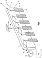
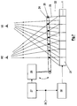
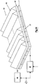
- Fig. 1 shows an example of a parallax barrier system with a variable viewing distance, wherein the parallax barrier system 4 is arranged in front of a display 1 and consists of a plurality of barrier strips 5, which are arranged parallel to each other and connected with a shaft 9 to a pantograph 6 at a joint pivot 8.
- the pantograph 6 has normal pivots 7 and joint pivots 8.
- the pantograph is connected with a moving rod 11 to a moving rod mechanism 12, which is controlled by a controller 13.
- one barrier strip 5, preverably the one in the middle is connected by a shaft 9f to a fixed point 10 in space.
- An according movement is controlled through the controller 13 by a viewer and/or by a control signal, value of which depends on the distance between the viewer and the display 1.
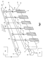
- Fig. 2 shows another embodiment of the inventive parallax barrier system, wherein the shafts 9 of the barrier strips 5 are connected to a rack and pinion mechanism 14 comprising a movable rack 15, which is linear, and pinions 16, which are arranged on top of the shafts 9 of the barrier strips 5.
- a rack and pinion mechanism 14 comprising a movable rack 15, which is linear, and pinions 16, which are arranged on top of the shafts 9 of the barrier strips 5.
- a moving rack mechanism 17 which is controlled by a controller 18
- the barrier strips 5 can be rotated, so that the angle between the barrier strips 5 and the display panel 1 will be changed, in other words the projection of the barrier strip area onto a plane parallel to the display plane 1 is changed.
- this system it is possible to achieve a suitable width of the barrier strips for the chosen pitch of the barrier strips.
- Controllers 13, 18 can be controlled e.g. by not shown input means by a viewer and/or by control signals, value of which depends on the distance between the viewer and the display 1.
- Fig. 3 shows a further embodiment of the parallax barrier system according to Fig. 1, wherein the parallax barrier system 4 is driven simultaneously from both sides with a moving rod 11 and 19 through a moving rod mechanism 12 and 20, which are both controlled by a single controller 13.
- Another difference of the embodiment according to Fig. 3 is, that none of the barrier strips is connected to a fixed point in space. Therefore, it is possible that the pantograph cannot only expand or contract, but also move parallel to the flat panel display 1 without expansion and contraction. Therefore the barrier strips move parallel to the flat panel display 1 and expands or contracts as parallel moving of viewer to the display and changing of viewing distance.
- the barriers 5 of the preferred embodiment can also be rotated.
- means 19 and 20 can also be provided without means 16 to 18.
- the pixels 2 dedicated to the right eye and pixels 3 dedicated to the left eye can be adopted accordingly by not shown controller means.
- FIG. 1 - 3 Another (not shown) embodiment of the principle shown by Fig. 1 - 3 can be realised by a liquid crystal element.
- an element can be light-transparent or non-transparent in dependence on according control signals, according light-blocking barriers can be displayed by the liquid crystal elements.
- the size and the distance between the barriers can be controlled by control signals, which can be determined by signals of input means and/or by signals of sensor means.
- the signal of the input means may be defined by a viewer or user, respectively and the sensor means may generate a signal e.g. in dependence on the distance between the viewer or user, respectively and the display 1.
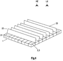
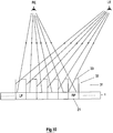
- Fig. 4 shows an embodiment of a moving barrier system 22, which is set on a flat panel display 1 consisting of pixels 21.
- the movable barrier system 22 consists of a plurality of movable barrier strips 23, which are set essentially perpendicular to the surface of the flat panel display 1, so that strips or columns of pixels are formed in the vertical direction.
- the enclosed angle between the movable barrier strips 23 and the surface of the flat panel display 1 can be changed, so that the rays can be directed to the right eye RE or left eye LA, respectively. This will be explained in more detall in fig. 5 and 6.
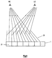
- Fig. 5 shows a cross section of the embodiment according to Fig. 4.
- the left eye LE which in turn means, that the flat panel display 1 displays in this case a complete left image.
- the right eye does not see any image from the surface from the flat panel display 1, but only sees the surfaces of the movable barrier strips.
- Fig. 6 shows the other case, wherein the surface of the flat panel display 1 consisting of the pixels 21 can only be seen by the right eye RE, because of the orientation of the movable barrier strips 23. For this reason, in this case the flat panel display 1 has to display a right image.
- the movable barrier strips 23 have to be changed in their directions according to the presence of the left respectively right image.
- the movement of the barrier strips has to be fast enough, e.g. more than 20 times per second, so that using the afterimage of the human eye a stereoscopic impression is created.
- Fig. 7 shows a cross section of an embodiment, wherein the movable barrier strips 23 of the movable barrier system 22 are moved by a joint arm 24.
- each movable barrier strip 23 is connected to a pivot 25 of the joint arm 24.
- the joint arm 24 is moved by a moving mechanism 26, which is controlled by a moving barrier controller 27.
- the display 1 is controlled by a display controller 28. Both controllers, the moving barrier controller 27 and the display controller 28, are controlled by a common timing signal 29, so that the movement of the joint arm 24 is synchronised with the change of the images depicted on the display 1.
- Fig. 8 shows another embodiment of a stereoscopic display system using a movable barrier system 22, which is not connected to the display 1, i.e. is independent from the display 1.
- the movable barrier system consists of a fixed arm 13 to which the movable barrier strips 23 are connected.
- the movable barrier strips 23 are moved by a joint arm 24 through the pivots 25 with a moving system 26. Control of the movement of the movable barrier system 22 and the images on the display 1 is done by the same controller arrangement as in the embodiment according to Fig. 7.
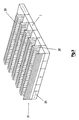
- Fig. 9 shows a stereoscopic display system, wherein the light rays between left and right eye are blocked in dependence on the state by a barrier system 31 consisting of fixed barrier strips 32 and movable barrier strips 33.
- the fixed barrier strips 32 are set perpendicular on top of the surface of the flat panel display 1, so that columns of pixels 21 are formed.
- On top of each fixed barrier strip 32 a movable barrier strip 33 is provided, which is in both viewing positions parallel to the surface of the display 1.
- Fig. 10 shows a cross section of the embodiment according to Fig. 9, wherein the movable barrier strips 33 are pointing to the left of Fig. 10, so that only the right eye can see the image on the surface of the display 1. The left eye only sees the surfaces of the fixed and/or movable barrier strips 32, 33.
- Fig. 11 shows the other case, in which only the left eye can see the image of the surface of the display 1, which in turn means that now the display 1 has to display a left image.
- the movable barrier strips 33 are now pointing to the right of Fig. 11.
- Fig. 12 shows another embodiment using the principle of Fig. 9.
- a plate or sheet 33a with parallel rectangular openings 33b and according frame 33b is provided on top of the fixed barrier strips 32 .
- the frame 33b forms the movable barrier strips.
- the plate as a whole can be moved by a moving mechanism 34, which is controlled by a controller 35.
- the image of the display 1 consisting of pixel 21 is controlled by a display controller 36.
- a common timing signal 37 switches between left image signals and right image signals and causes the exact synchronous movement of the plate of movable barrier strips 33.
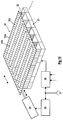
- Fig. 13 shows a second embodiment of the stereoscopic display system using a plate or sheet 33a.
- the openings 33b and the frame 33c are formed by a liquid crystal system 38.
- the orientation of the liquid crystal system is parallel to the image plane of the flat panel display 1.
- the liquid crystal system 38 comprises strips of liquid crystal shutters 39 and 40, which are arranged along the pixel columns and function as moving barriers 33. These liquid crystal shutters 39 and 40 can switch in dependence on the state from transparent to not-transparent and vice versa, which gives the same function as the moving barriers 33 in the Figures 9 and 12.
- shutter 39 realises the frame 33c and shutter 40 realises openings 33b.
- the function of the liquid crystal shutters is controlled by a controller 41, which is synchronised with the display controller 36 through the common timing signal 37.
- the display 1 is controlled by the controller 36 such that no loss of picture images occur.
- the according effect is indicated in Fig. 10 and 11, where it can be seen that only a part of the right pixel RP can be seen by the right eye RE (Fig. 10) and that only a part of the left pixel LP can be seen by the left eye LE (Fig. 11).
- the controller 36 can be controlled accordingly by an input of a user and/or by a signal, value of which depends on the distance between a viewer (who can be identical with the user) and the display 1.
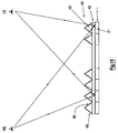
- Fig. 14 shows a stereoscopic display system using polarized light for creating the stereoscopic effect.
- a polarizing device 42 On top of a flat panel display 1 consisting of pixels 21 a polarizing device 42 is provided, which polarizes the light emanating from the pixels 21.
- rows of polarizing prisms 43 are provided, so that the bottom of each prism 43 covers one row of pixels 21.
- These polarizing prisms 43 form a polarizing prism sheet 44.
- the polarizing device 44 is controlled by a controller 45, whereas the display 1 is controlled by a display controller 46. Both controllers 45, 46 are timed by a common timing signal 47.
- Fig. 15 shows the stereoscopic display system according to Fig. 14 in cross section.
- the flat panel display 1 is overlaid by the polarizing device 42, on top of which a polarizing prism sheet 44 consisting of rows of prisms 43 rests.
- the left eye LE sees only the right side surface 48 of the polarizing prisms 43
- the right eye RE only sees the left side surface 49 of the polarizing prism.
- the flat panel display displays left eye image.
- the rays of the flat panel display 1 are not able to project from the left side surface 49 of the polarizing prism 43, because the polarization direction of the polarizing device 42 is perpendicular to the polarization direction of the left side surface of the polarizing prism 43.
- the polarization direction of the polarizing device 42 is changed to the other direction and it is parallel to polarizing direction of the left side surface 49 of the polarizing prism 43.
- the flat panel display displays right eye image.
- rays of the flat panel display are not able to project from right side surface 48 of the polarizing prism.
- the polarizing direction of the polarizing device 42 is changed again to the first polarization direction.
- the display 1 displays right eye image and left eye image alternately, so that the right eye sees only right image and the left sees only left image in a time sharing manner. Therefore, if the above operation is fast enough, a stereoscopic image by the effect of after image and binocular parallax is created.
- Fig. 16 shows a cross section through a stereoscopic display using polarized light, wherein the shapes of the polarizing prisms 43 of the polarizing prism sheet 44 differ from each other.
- the height of the prisms 42 decrease from the outer areas to the middle of the display 1, i.e an "outer" prism is higher than it adjacent "inner” prism. With such an arrangement the cross talk of left image ray and right image ray is decreased in comparison to the prism shape according to Fig. 15.
- Fig. 17 shows another embodiment of the stereoscopic display system using polarized light, wherein the shapes of the polarizing prisms is different as in the embodiment of Fig. 16, but further the prisms overhang each other, seen from the outside to the middle of the display 1, i.e. an "outer"prism overlaps an adjacent inner prism. With such an arrangement and shape it is possible to use a wider display than the interpupil length.
Landscapes
- Physics & Mathematics (AREA)
- Engineering & Computer Science (AREA)
- Multimedia (AREA)
- Signal Processing (AREA)
- General Physics & Mathematics (AREA)
- Optics & Photonics (AREA)
- Geometry (AREA)
- Testing, Inspecting, Measuring Of Stereoscopic Televisions And Televisions (AREA)
- Liquid Crystal (AREA)
- Stereoscopic And Panoramic Photography (AREA)
Applications Claiming Priority (2)
| Application Number | Priority Date | Filing Date | Title |
|---|---|---|---|
| GB9525308A GB2308258A (en) | 1995-12-11 | 1995-12-11 | Stereoscopic display system |
| GB9525308 | 1995-12-11 |
Publications (3)
| Publication Number | Publication Date |
|---|---|
| EP0779531A2 true EP0779531A2 (fr) | 1997-06-18 |
| EP0779531A3 EP0779531A3 (fr) | 1999-10-13 |
| EP0779531B1 EP0779531B1 (fr) | 2003-12-03 |
Family
ID=10785252
Family Applications (1)
| Application Number | Title | Priority Date | Filing Date |
|---|---|---|---|
| EP96119334A Expired - Lifetime EP0779531B1 (fr) | 1995-12-11 | 1996-12-03 | Dispositif d'affichage stéréoscopique |
Country Status (6)
| Country | Link |
|---|---|
| US (1) | US5900972A (fr) |
| EP (1) | EP0779531B1 (fr) |
| JP (1) | JP3904643B2 (fr) |
| CN (1) | CN1119690C (fr) |
| DE (1) | DE69630939T2 (fr) |
| GB (1) | GB2308258A (fr) |
Cited By (6)
| Publication number | Priority date | Publication date | Assignee | Title |
|---|---|---|---|---|
| WO2000016158A1 (fr) * | 1998-09-10 | 2000-03-23 | Techno-Color, Spol. S R.O. | Procede de production d'une photographie a effet stereoscopique |
| WO2003019952A1 (fr) * | 2001-08-21 | 2003-03-06 | Koninklijke Philips Electronics N.V. | Affichage autostereoscopique s'adaptant a l'observateur |
| GB2405043A (en) * | 2003-08-13 | 2005-02-16 | Sharp Kk | Compensation for refraction effects in an autostereoscopic display |
| WO2005018240A1 (fr) * | 2003-08-12 | 2005-02-24 | Neuratron Group Limited | Dispositif d'imagerie stereoscopique et son moyen de construction |
| WO2007136348A1 (fr) * | 2006-05-18 | 2007-11-29 | Bracco Imaging S.P.A. | Procédés et appareils pour un affichage stéréographique |
| WO2010049741A3 (fr) * | 2008-10-27 | 2010-06-17 | Pados Karoly | Plaque d'adaptation pour dispositif d'affichage et procédé de production d'une visualisation stéréoscopique à une distance d'observation donnée |
Families Citing this family (22)
| Publication number | Priority date | Publication date | Assignee | Title |
|---|---|---|---|---|
| WO2000041399A1 (fr) * | 1999-01-06 | 2000-07-13 | Hideyoshi Horimai | Dispositif et procede de detection d'une image tridimensionnelle, dispositif et procede d'affichage d'une image tridimensionnelle, et dispositif et procede permettant de changer la position d'une image tridimensionnelle |
| EP1087627A3 (fr) * | 1999-09-24 | 2004-02-18 | SANYO ELECTRIC Co., Ltd. | Dispositif d'affichage d'images autostéréoscopiques |
| US6546208B1 (en) | 1999-11-22 | 2003-04-08 | Sl3D, Inc. | Stereoscopic telescope with camera |
| US6504649B1 (en) * | 2000-01-13 | 2003-01-07 | Kenneth J. Myers | Privacy screens and stereoscopic effects devices utilizing microprism sheets |
| AU2001253115A1 (en) * | 2000-04-27 | 2001-11-12 | Greenberg, Edward | Improved microprism sheets and privacy screens utilizing same |
| US20020101658A1 (en) * | 2001-01-29 | 2002-08-01 | Reuben Hoppenstein | Electronic virtual lens for observing 3-D or 4-D images |
| US20040017334A1 (en) * | 2002-07-26 | 2004-01-29 | Chan Hau Man | Three-dimensional image display |
| CN1751525B (zh) * | 2003-02-21 | 2012-02-01 | 皇家飞利浦电子股份有限公司 | 自动立体显示器 |
| JP4589013B2 (ja) * | 2004-02-23 | 2010-12-01 | 三洋電機株式会社 | 投写型映像表示装置用のシャッタ装置及び投写型映像表示装置 |
| CN1301420C (zh) * | 2004-03-25 | 2007-02-21 | 南京大学 | 双微偏振式自由立体成像装置及其方法 |
| JP4327758B2 (ja) * | 2005-03-24 | 2009-09-09 | 株式会社東芝 | 立体画像表示装置 |
| KR100586221B1 (ko) * | 2005-05-09 | 2006-06-07 | (주)실리콘화일 | 평면 표시 장치를 이용한 3차원 영상 표시 장치 |
| KR101320637B1 (ko) * | 2006-01-23 | 2013-11-13 | (주)쓰리디아이에스 | 망형의 입체 화상 표시 장치 |
| US8189143B2 (en) | 2006-04-17 | 2012-05-29 | Panasonic Corporation | Display device |
| JP5021389B2 (ja) * | 2007-07-30 | 2012-09-05 | 独立行政法人情報通信研究機構 | 画像表示装置 |
| CN101364364B (zh) * | 2008-07-10 | 2014-11-26 | 湖南创图视维科技有限公司 | Led大尺寸自由立体显示技术 |
| US8368690B1 (en) | 2011-07-05 | 2013-02-05 | 3-D Virtual Lens Technologies, Inc. | Calibrator for autostereoscopic image display |
| DE102012205271B3 (de) * | 2012-03-30 | 2013-07-18 | Carl Zeiss Vision International Gmbh | Visualisierungssystem für dreidimensionale Bilder |
| JP6477680B2 (ja) * | 2013-03-25 | 2019-03-06 | イェーガー、ヨーゼフ | 振動グリッド型空間生成装置 |
| CN104090378B (zh) * | 2014-07-11 | 2016-06-08 | 京东方科技集团股份有限公司 | 一种防窥装置及防窥方法 |
| CN108681155B (zh) * | 2018-05-16 | 2021-03-05 | 京东方科技集团股份有限公司 | 一种显示装置、显示系统及其控制方法 |
| DE102018129891A1 (de) * | 2018-11-27 | 2020-05-28 | Bayerische Motoren Werke Aktiengesellschaft | Darstellung von Bildinformationen in einem Kraftfahrzeug mit einem Dach-Display |
Family Cites Families (7)
| Publication number | Priority date | Publication date | Assignee | Title |
|---|---|---|---|---|
| US4740073A (en) * | 1982-12-27 | 1988-04-26 | Meacham G B Kirby | System for projecting three-dimensional images |
| US4588259A (en) * | 1984-07-31 | 1986-05-13 | Bright & Morning Star Company | Stereoscopic optical system |
| US4719507A (en) * | 1985-04-26 | 1988-01-12 | Tektronix, Inc. | Stereoscopic imaging system with passive viewing apparatus |
| US4807965A (en) * | 1987-05-26 | 1989-02-28 | Garakani Reza G | Apparatus for three-dimensional viewing |
| US4963959A (en) * | 1989-11-20 | 1990-10-16 | Drewlo Kenneth G | Three-dimensional cathode ray tube display |
| JPH05122733A (ja) * | 1991-10-28 | 1993-05-18 | Nippon Hoso Kyokai <Nhk> | 3次元画像表示装置 |
| US5264964A (en) * | 1991-12-18 | 1993-11-23 | Sades Faris | Multi-mode stereoscopic imaging system |
-
1995
- 1995-12-11 GB GB9525308A patent/GB2308258A/en not_active Withdrawn
-
1996
- 1996-12-02 JP JP32189596A patent/JP3904643B2/ja not_active Expired - Fee Related
- 1996-12-03 DE DE69630939T patent/DE69630939T2/de not_active Expired - Lifetime
- 1996-12-03 EP EP96119334A patent/EP0779531B1/fr not_active Expired - Lifetime
- 1996-12-04 CN CN96121864A patent/CN1119690C/zh not_active Expired - Lifetime
- 1996-12-09 US US08/761,955 patent/US5900972A/en not_active Expired - Lifetime
Non-Patent Citations (1)
| Title |
|---|
| None |
Cited By (6)
| Publication number | Priority date | Publication date | Assignee | Title |
|---|---|---|---|---|
| WO2000016158A1 (fr) * | 1998-09-10 | 2000-03-23 | Techno-Color, Spol. S R.O. | Procede de production d'une photographie a effet stereoscopique |
| WO2003019952A1 (fr) * | 2001-08-21 | 2003-03-06 | Koninklijke Philips Electronics N.V. | Affichage autostereoscopique s'adaptant a l'observateur |
| WO2005018240A1 (fr) * | 2003-08-12 | 2005-02-24 | Neuratron Group Limited | Dispositif d'imagerie stereoscopique et son moyen de construction |
| GB2405043A (en) * | 2003-08-13 | 2005-02-16 | Sharp Kk | Compensation for refraction effects in an autostereoscopic display |
| WO2007136348A1 (fr) * | 2006-05-18 | 2007-11-29 | Bracco Imaging S.P.A. | Procédés et appareils pour un affichage stéréographique |
| WO2010049741A3 (fr) * | 2008-10-27 | 2010-06-17 | Pados Karoly | Plaque d'adaptation pour dispositif d'affichage et procédé de production d'une visualisation stéréoscopique à une distance d'observation donnée |
Also Published As
| Publication number | Publication date |
|---|---|
| DE69630939T2 (de) | 2004-11-04 |
| CN1155092A (zh) | 1997-07-23 |
| CN1119690C (zh) | 2003-08-27 |
| GB2308258A (en) | 1997-06-18 |
| JP3904643B2 (ja) | 2007-04-11 |
| US5900972A (en) | 1999-05-04 |
| JPH09236776A (ja) | 1997-09-09 |
| EP0779531B1 (fr) | 2003-12-03 |
| DE69630939D1 (de) | 2004-01-15 |
| EP0779531A3 (fr) | 1999-10-13 |
| GB9525308D0 (en) | 1996-02-07 |
Similar Documents
| Publication | Publication Date | Title |
|---|---|---|
| US5900972A (en) | Stereoscopic display system | |
| US6710920B1 (en) | Stereoscopic display | |
| US8284241B2 (en) | High resolution autostereoscopic display apparatus with interlaced image | |
| JP3229824B2 (ja) | 立体映像表示装置 | |
| US7626644B2 (en) | Multiview autostereoscopic display | |
| US7786953B2 (en) | Apparatus displaying three-dimensional image | |
| JP2846856B2 (ja) | 立体映像表示装置 | |
| EP2062444B1 (fr) | Affichage autostéréoscopique multivue à résolution améliorée | |
| US5825541A (en) | Stereoscopic display system | |
| EP0829743B1 (fr) | Dispositif d'affichage directionnel avec système de suivi de l'observateur | |
| KR100728204B1 (ko) | 2차원 영상과 3차원 영상 겸용 디스플레이 장치 | |
| JP2004503802A (ja) | 構造化光源 | |
| JP2000503424A (ja) | 自動立体表示装置 | |
| US10750101B2 (en) | Resolution for autostereoscopic video displays | |
| US8629945B2 (en) | 3D liquid crystal display system | |
| US7607780B2 (en) | Projection-type 3-D image display using single projector | |
| JP2953433B2 (ja) | 立体表示装置 | |
| US8427591B2 (en) | 3D liquid crystal display system | |
| KR100658670B1 (ko) | 입체 영상 디스플레이 장치 | |
| EP3556087A2 (fr) | Caméra panoramique | |
| KR20050016344A (ko) | 자동 입체 디스플레이 | |
| JPH06105341A (ja) | 立体視表示方法 |
Legal Events
| Date | Code | Title | Description |
|---|---|---|---|
| PUAI | Public reference made under article 153(3) epc to a published international application that has entered the european phase |
Free format text: ORIGINAL CODE: 0009012 |
|
| AK | Designated contracting states |
Kind code of ref document: A2 Designated state(s): DE FR GB IT |
|
| RAP1 | Party data changed (applicant data changed or rights of an application transferred) |
Owner name: THOMSON MULTIMEDIA |
|
| PUAL | Search report despatched |
Free format text: ORIGINAL CODE: 0009013 |
|
| AK | Designated contracting states |
Kind code of ref document: A3 Designated state(s): DE FR GB IT |
|
| 17P | Request for examination filed |
Effective date: 20000412 |
|
| 17Q | First examination report despatched |
Effective date: 20020716 |
|
| GRAH | Despatch of communication of intention to grant a patent |
Free format text: ORIGINAL CODE: EPIDOS IGRA |
|
| GRAS | Grant fee paid |
Free format text: ORIGINAL CODE: EPIDOSNIGR3 |
|
| GRAA | (expected) grant |
Free format text: ORIGINAL CODE: 0009210 |
|
| AK | Designated contracting states |
Kind code of ref document: B1 Designated state(s): DE FR GB IT |
|
| PG25 | Lapsed in a contracting state [announced via postgrant information from national office to epo] |
Ref country code: IT Free format text: LAPSE BECAUSE OF FAILURE TO SUBMIT A TRANSLATION OF THE DESCRIPTION OR TO PAY THE FEE WITHIN THE PRE;WARNING: LAPSES OF ITALIAN PATENTS WITH EFFECTIVE DATE BEFORE 2007 MAY HAVE OCCURRED AT ANY TIME BEFORE 2007. THE CORRECT EFFECTIVE DATE MAY BE DIFFERENT FROM THE ONE RECORDED.SCRIBED TIME-LIMIT Effective date: 20031203 |
|
| REG | Reference to a national code |
Ref country code: GB Ref legal event code: FG4D |
|
| REF | Corresponds to: |
Ref document number: 69630939 Country of ref document: DE Date of ref document: 20040115 Kind code of ref document: P |
|
| ET | Fr: translation filed | ||
| PLBE | No opposition filed within time limit |
Free format text: ORIGINAL CODE: 0009261 |
|
| STAA | Information on the status of an ep patent application or granted ep patent |
Free format text: STATUS: NO OPPOSITION FILED WITHIN TIME LIMIT |
|
| 26N | No opposition filed |
Effective date: 20040906 |
|
| PGFP | Annual fee paid to national office [announced via postgrant information from national office to epo] |
Ref country code: DE Payment date: 20141219 Year of fee payment: 19 |
|
| PGFP | Annual fee paid to national office [announced via postgrant information from national office to epo] |
Ref country code: GB Payment date: 20150105 Year of fee payment: 19 Ref country code: FR Payment date: 20141215 Year of fee payment: 19 |
|
| REG | Reference to a national code |
Ref country code: DE Ref legal event code: R119 Ref document number: 69630939 Country of ref document: DE |
|
| GBPC | Gb: european patent ceased through non-payment of renewal fee |
Effective date: 20151203 |
|
| REG | Reference to a national code |
Ref country code: FR Ref legal event code: ST Effective date: 20160831 |
|
| PG25 | Lapsed in a contracting state [announced via postgrant information from national office to epo] |
Ref country code: DE Free format text: LAPSE BECAUSE OF NON-PAYMENT OF DUE FEES Effective date: 20160701 Ref country code: GB Free format text: LAPSE BECAUSE OF NON-PAYMENT OF DUE FEES Effective date: 20151203 |
|
| PG25 | Lapsed in a contracting state [announced via postgrant information from national office to epo] |
Ref country code: FR Free format text: LAPSE BECAUSE OF NON-PAYMENT OF DUE FEES Effective date: 20151231 |