EP0780065A1 - Montiermaschine für Oberteil und Sohle eines Schuhes - Google Patents
Montiermaschine für Oberteil und Sohle eines Schuhes Download PDFInfo
- Publication number
- EP0780065A1 EP0780065A1 EP96420359A EP96420359A EP0780065A1 EP 0780065 A1 EP0780065 A1 EP 0780065A1 EP 96420359 A EP96420359 A EP 96420359A EP 96420359 A EP96420359 A EP 96420359A EP 0780065 A1 EP0780065 A1 EP 0780065A1
- Authority
- EP
- European Patent Office
- Prior art keywords
- sole
- plate
- rod
- robot
- conveyor
- Prior art date
- Legal status (The legal status is an assumption and is not a legal conclusion. Google has not performed a legal analysis and makes no representation as to the accuracy of the status listed.)
- Granted
Links
- 239000003292 glue Substances 0.000 claims description 5
- 238000004519 manufacturing process Methods 0.000 claims description 5
- 230000000903 blocking effect Effects 0.000 claims description 4
- 238000009434 installation Methods 0.000 claims description 4
- 210000000078 claw Anatomy 0.000 claims description 3
- 230000007420 reactivation Effects 0.000 claims description 3
- 125000006850 spacer group Chemical group 0.000 claims description 3
- 238000001035 drying Methods 0.000 claims description 2
- 239000000853 adhesive Substances 0.000 abstract 1
- 230000001070 adhesive effect Effects 0.000 abstract 1
- 230000007246 mechanism Effects 0.000 abstract 1
- 238000000034 method Methods 0.000 description 2
- 230000000295 complement effect Effects 0.000 description 1
- 238000005457 optimization Methods 0.000 description 1
- 230000000149 penetrating effect Effects 0.000 description 1
Images


Classifications
-
- A—HUMAN NECESSITIES
- A43—FOOTWEAR
- A43D—MACHINES, TOOLS, EQUIPMENT OR METHODS FOR MANUFACTURING OR REPAIRING FOOTWEAR
- A43D111/00—Shoe machines with conveyors for jacked shoes or for shoes or shoe parts
-
- A—HUMAN NECESSITIES
- A43—FOOTWEAR
- A43D—MACHINES, TOOLS, EQUIPMENT OR METHODS FOR MANUFACTURING OR REPAIRING FOOTWEAR
- A43D117/00—Racks for receiving or transporting shoes or shoe parts; Other conveying means
-
- A—HUMAN NECESSITIES
- A43—FOOTWEAR
- A43D—MACHINES, TOOLS, EQUIPMENT OR METHODS FOR MANUFACTURING OR REPAIRING FOOTWEAR
- A43D119/00—Driving or controlling mechanisms of shoe machines; Frames for shoe machines
Definitions
- the present invention relates to a device for assembling the upper and the sole of a shoe, in an at least partially automated installation for manufacturing shoes.
- a conveyor intended for the transport of trays, some of which have shapes which are first coated with rods, and others of which carry soles.
- the object of the invention is to provide an assembly device which offers the maximum number of possibilities for making shoes, by allowing for shoes whose sole has a simple shape, such as a bowl, a fully automatic assembly, so than in other types of footwear where the sole is more complex, it must be used at least partially manual assembly.
- the trays are identified by a memory device indicating the type of products it carries, upper or sole, and also the method of product assembly, automatic assembly or manual assembly.
- a computer associated with the installation then controls the robot either to perform automatic assembly, or to transfer the rod to the manual assembly station.
- the table is equipped, in each zone corresponding to the reference position of a plate carrying a sole, with claws mounted on jacks, forming spacers intended to open the rim of the sole to facilitate mounting of the rod on this one.
- the means control successively cause the robot arm to take up a shape fitted with a rod, turn it over and transfer it to the sole against which the shape and the rod are applied after the edges of the sole have been separated, the assembly thus obtained thanks to the reactivation of the glue that the sole and / or the upper contains locally, carried out when the plates arrive on the table, then being transferred by the robot to the press, which keeps the assembly under pressure during the drying time of the glue, before a new transfer on the table top, which originally served to bring the form equipped with the rod.
- the press comprises at least one support provided with means for receiving the form equipped with the upper and the sole, identical to those equipping the plates intended for transporting the forms.
- the means for receiving the form can be constituted, for example, by two vertical and profiled fingers, while the form is equipped, for its part, with two complementary tubular elements, each tubular element possibly comprising, at its periphery, at least a groove for gripping by the robot arm.
- the manual assembly station of a rod and a sole comprises a column fixed to the ground and on the upper part of which a plate is pivotally mounted under the action of a jack between a horizontal position and a substantially vertical position, this plate carrying a support provided with means for receiving the form equipped with the rod, identical to those equipping the plates intended for transporting the forms, and means for blocking the form.
- the robot brings the form equipped with the rod, while the plate of the assembly station is in a horizontal position.
- the operator causes this plate to pivot in a vertical position in order to be able to more easily assemble the sole on the upper.
- the plate is also pivotally mounted about an axis which is perpendicular to it, and is associated with a rotary actuator intended to ensure its return movement towards the reference position, after assembly of the sole and of the rod, to allow its gripping by the robot arm.
- the operator can then freely rotate the plate and the form mounted on it around this second axis to carry out the assembly. of the sole.
- the operator need only activate a command which, by means of the rotary actuator and the pivoting actuator about a horizontal axis, returns the plate to the horizontal position, with indexing in the reference position. for the grip of the upper and sole assembly by the robot arm.
- each sole rests on a plate itself mounted on a plate using the same positioning means as those used for the shapes, this plate carrying, on its upper face, a fixed rear stop, two lateral stops. and a front stop movable longitudinally and subjected to the action of springs tending to move it backwards.
- each sole is therefore made from the heel thereof, the position of which is always the same regardless of the size of the sole.
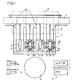
- the device according to the invention is associated with a conveyor 2 intended for the transport of trays 3, some of which have shapes 4 coated with rods 5, and the others of which carry soles 6.
- the device comprises a table 7 comprising four tracks 8 perpendicular to the conveyor and each provided with a transfer device 9 having in particular a jack, this device being capable of moving a plate 3 between the conveyor, where the plate 3 is immobilized by stops stop 10, and a reference position remote from the conveyor.
- the transfer device is also intended to make the reverse path pass through the plate, that is to say from the reference position remote from the conveyor to the conveyor.
- the device represented in FIG. 1 comprises a table 7 equipped with four tracks 8, which makes it possible to have simultaneously on the table four trays, two of which carry shapes 4 and the other two of which carry soles 6.
- a robot 12 On the side of the table opposite the conveyor is arranged a robot 12, on either side of which are mounted, on the one hand, a press 13 with two assembly zones and on the other hand, an assembly station 14 manual with two assembly zones.
- Each sole 6 rests, not directly on a plate 3, but on a plate 15.
- Each plate 15 is provided with two tubular parts 16 projecting downwards, engaged on two fingers 17 projecting from the upper face of a plate .
- the tubular elements 16 have notches 18 allowing gripping by the robot arm 12.
- the plate 15 comprises, as shown in particular in Figure 5, fixed stops 19 at the rear, to immobilize the heel, adjustable lateral stops 20, and a front stop 22 movable in the rear direction via d 'a spring 23. Consequently, the positioning of each sole 6 as a function of the size of the sole is identified from its heel since it is the heel stop 19 which is the fixed reference point.
- each track 8 intended to receive a plate 3 equipped with a sole 6 is associated with claw elements 25 mounted on jacks 26, forming spacers capable of moving outward the edge 21 of a sole in the general shape of a bowl.
- the assembly can be carried out automatically.
- the robot grips the form 4, by means of the tubular parts 27 of these engaged on the fingers 17 of the plate 3, ensures the reversal of the form and comes to apply it equipped with the rod 5 on the sole 6.
- adhesion occurs between the sole and the rod.
- the assembly is transferred by the robot 12 to the press 13, where the shape is engaged by means of its tubular parts 27 on rods 28 similar to the rods 17 of the plates 3.
- the robot performs another operation, such as for example the transfer of the shape + upper + sole assembly from the area adjacent to the press to a free plate 3, for the evacuation of the assembly thus carried out to the next station.
- the robot 12 ensures, under the conditions indicated above, the transfer of the shape and the rod to the manual assembly station 14.
- This comprises a vertical column 29 on the upper part of which is mounted a plate 30.
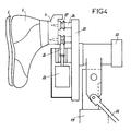
- This plate 30 is able to pivot between a horizontal position shown in FIG. 3 as far as a vertical position shown in FIG. 4 by means of a jack 32.
- This plate 30 can also pivot around an axis , which is perpendicular thereto, this second pivoting movement being associated with a rotary actuator 33.
- the plate 30 comprises two fingers 34 similar to the fingers 17 of the plates 3, intended to receive the form 4. In practice, the form 4 is brought to the plate in the position of Figure 3.
- a blocking cylinder 35 is provided, the end of the rod of which is fitted with a cleat 36 penetrating into a recess of a tubular element 27 of the shape.
- the robot arm then resumes assembly to bring it to a tray 3 waiting in the store, this tray 3 being evacuated by the jack 9 to the conveyor 2 for the further manufacture of the shoe.
- the invention brings a great improvement to the existing technique by providing a device intended for the assembly of an upper and a shoe sole, of simple design, offering a plurality of possibilities of '', and allowing an optimization of the work of the robot.
- the invention is not limited to the sole embodiment of this device described above by way of example, on the contrary it embraces all variants.
- the number of tracks of the table could be different, or that the means of movement of each tray on a track could be different, without departing from the scope of the invention.
Landscapes
- Footwear And Its Accessory, Manufacturing Method And Apparatuses (AREA)
- Automatic Assembly (AREA)
Applications Claiming Priority (2)
| Application Number | Priority Date | Filing Date | Title |
|---|---|---|---|
| FR9515207 | 1995-12-18 | ||
| FR9515207A FR2742313B1 (fr) | 1995-12-18 | 1995-12-18 | Dispositif d'assemblage de la tige et de la semelle d'une chaussure |
Publications (2)
| Publication Number | Publication Date |
|---|---|
| EP0780065A1 true EP0780065A1 (de) | 1997-06-25 |
| EP0780065B1 EP0780065B1 (de) | 2001-04-04 |
Family
ID=9485755
Family Applications (1)
| Application Number | Title | Priority Date | Filing Date |
|---|---|---|---|
| EP96420359A Expired - Lifetime EP0780065B1 (de) | 1995-12-18 | 1996-12-18 | Montiermaschine für Oberteil und Sohle eines Schuhes |
Country Status (5)
| Country | Link |
|---|---|
| US (1) | US5768732A (de) |
| EP (1) | EP0780065B1 (de) |
| AT (1) | ATE200193T1 (de) |
| DE (1) | DE69612360D1 (de) |
| FR (1) | FR2742313B1 (de) |
Cited By (8)
| Publication number | Priority date | Publication date | Assignee | Title |
|---|---|---|---|---|
| ES2142239A1 (es) * | 1997-08-04 | 2000-04-01 | Univ Murcia | Robot con vision artificial para encolado automatico de suelas de zapato. |
| EP2337675A4 (de) * | 2008-09-26 | 2014-02-19 | Nike International Ltd | Fixierungs- und montagearmatur zur schuhherstellung |
| EP2780849A4 (de) * | 2011-11-18 | 2015-10-21 | Nike Innovate Cv | Automatisierte identifizierung von schuhteilen |
| EP2780847A4 (de) * | 2011-11-18 | 2015-11-11 | Nike Innovate Cv | Automatisierte identifikation und montage von schuhteilen |
| EP3318153A1 (de) * | 2016-11-04 | 2018-05-09 | adidas AG | Verfahren und vorrichtung zum verbinden eines sohlenelements mit einem schuhoberteilelement |
| US9968163B2 (en) | 2008-09-26 | 2018-05-15 | Nike, Inc. | Unitary multi-use alignment fixture for shoe production |
| US10552551B2 (en) | 2011-11-18 | 2020-02-04 | Nike, Inc. | Generation of tool paths for shore assembly |
| US12313395B2 (en) | 2011-11-18 | 2025-05-27 | Nike, Inc. | Automated 3-D modeling of shoe parts |
Families Citing this family (7)
| Publication number | Priority date | Publication date | Assignee | Title |
|---|---|---|---|---|
| US8958901B2 (en) | 2011-11-18 | 2015-02-17 | Nike, Inc. | Automated manufacturing of shoe parts |
| CN103989293B (zh) * | 2014-05-23 | 2016-09-28 | 芜湖风雪橡胶有限公司 | 用于运输鞋具的装置 |
| CN104824920B (zh) * | 2015-05-20 | 2017-05-10 | 东莞市鑫拓智能机械科技有限公司 | 一种机器人自动垫鞋垫机 |
| CN105495869B (zh) * | 2016-01-25 | 2018-05-25 | 湖州练市辉煌鞋业有限公司 | 制鞋用皮料打磨机的输送装置 |
| CN108523314B (zh) * | 2018-05-29 | 2024-02-23 | 浙江柱达机械科技有限公司 | 中后帮弹性指压装置 |
| CN111331156B (zh) * | 2018-12-19 | 2021-06-22 | 宝成工业股份有限公司 | 自动上下料装置 |
| CN116869254B (zh) * | 2023-08-09 | 2025-11-28 | 泉州华数机器人有限公司 | 一种鞋底与鞋面精准配双的装置及方法 |
Citations (4)
| Publication number | Priority date | Publication date | Assignee | Title |
|---|---|---|---|---|
| FR2566635A1 (fr) * | 1984-06-29 | 1986-01-03 | Huber Auguste | Dispositif de transfert automatique d'une chaussure entre des machines |
| US4765011A (en) * | 1987-01-28 | 1988-08-23 | International Shoe Machine Corporation | Mechanism to transfer a footwear upper assembly between stations of a multi-station system |
| EP0591596A1 (de) * | 1992-03-27 | 1994-04-13 | COMELZ S.p.A. | Automatisches Schuhherstellungssystem, insbesondere zur Aufrauhung und Verklebung von Schuhschäften |
| FR2705872A1 (fr) * | 1993-06-04 | 1994-12-09 | Blanc Roger | Dispositif de préhension d'une forme pour la fabrication de chaussures. |
Family Cites Families (3)
| Publication number | Priority date | Publication date | Assignee | Title |
|---|---|---|---|---|
| US3024480A (en) * | 1960-05-12 | 1962-03-13 | United Shoe Machinery Corp | Shoe handling devices |
| FR2435220A1 (fr) * | 1978-09-06 | 1980-04-04 | Bonnet Pierre | Installation pour la production de chaussures |
| US4769866A (en) * | 1986-11-21 | 1988-09-13 | International Shoe Machine Corporation | Multi-station system to act upon footwear upper assemblies with transfer between stations thereof |
-
1995
- 1995-12-18 FR FR9515207A patent/FR2742313B1/fr not_active Expired - Fee Related
-
1996
- 1996-12-17 US US08/761,076 patent/US5768732A/en not_active Expired - Lifetime
- 1996-12-18 DE DE69612360T patent/DE69612360D1/de not_active Expired - Lifetime
- 1996-12-18 AT AT96420359T patent/ATE200193T1/de not_active IP Right Cessation
- 1996-12-18 EP EP96420359A patent/EP0780065B1/de not_active Expired - Lifetime
Patent Citations (4)
| Publication number | Priority date | Publication date | Assignee | Title |
|---|---|---|---|---|
| FR2566635A1 (fr) * | 1984-06-29 | 1986-01-03 | Huber Auguste | Dispositif de transfert automatique d'une chaussure entre des machines |
| US4765011A (en) * | 1987-01-28 | 1988-08-23 | International Shoe Machine Corporation | Mechanism to transfer a footwear upper assembly between stations of a multi-station system |
| EP0591596A1 (de) * | 1992-03-27 | 1994-04-13 | COMELZ S.p.A. | Automatisches Schuhherstellungssystem, insbesondere zur Aufrauhung und Verklebung von Schuhschäften |
| FR2705872A1 (fr) * | 1993-06-04 | 1994-12-09 | Blanc Roger | Dispositif de préhension d'une forme pour la fabrication de chaussures. |
Cited By (21)
| Publication number | Priority date | Publication date | Assignee | Title |
|---|---|---|---|---|
| ES2142239A1 (es) * | 1997-08-04 | 2000-04-01 | Univ Murcia | Robot con vision artificial para encolado automatico de suelas de zapato. |
| US9968163B2 (en) | 2008-09-26 | 2018-05-15 | Nike, Inc. | Unitary multi-use alignment fixture for shoe production |
| EP2337675A4 (de) * | 2008-09-26 | 2014-02-19 | Nike International Ltd | Fixierungs- und montagearmatur zur schuhherstellung |
| US9095191B2 (en) | 2008-09-26 | 2015-08-04 | Nike, Inc. | Stockfit assembly fixture for shoe production |
| US11341291B2 (en) | 2011-11-18 | 2022-05-24 | Nike, Inc. | Generation of tool paths for shoe assembly |
| US11266207B2 (en) | 2011-11-18 | 2022-03-08 | Nike, Inc. | Automated identification and assembly of shoe parts |
| US12313395B2 (en) | 2011-11-18 | 2025-05-27 | Nike, Inc. | Automated 3-D modeling of shoe parts |
| EP2780847A4 (de) * | 2011-11-18 | 2015-11-11 | Nike Innovate Cv | Automatisierte identifikation und montage von schuhteilen |
| EP3361403A1 (de) * | 2011-11-18 | 2018-08-15 | NIKE Innovate C.V. | Automatisierte identifizierung von schuhteilen |
| US10194716B2 (en) | 2011-11-18 | 2019-02-05 | Nike, Inc. | Automated identification and assembly of shoe parts |
| CN110223353A (zh) * | 2011-11-18 | 2019-09-10 | 耐克创新有限合伙公司 | 鞋零件的自动化识别和组装 |
| US10552551B2 (en) | 2011-11-18 | 2020-02-04 | Nike, Inc. | Generation of tool paths for shore assembly |
| EP3689175A1 (de) * | 2011-11-18 | 2020-08-05 | NIKE Innovate C.V. | Automatisierte identifikation und montage von schuhteilen |
| CN110223353B (zh) * | 2011-11-18 | 2024-04-26 | 耐克创新有限合伙公司 | 鞋零件的自动化识别和组装 |
| US11317681B2 (en) | 2011-11-18 | 2022-05-03 | Nike, Inc. | Automated identification of shoe parts |
| EP2780849A4 (de) * | 2011-11-18 | 2015-10-21 | Nike Innovate Cv | Automatisierte identifizierung von schuhteilen |
| EP4062790A1 (de) * | 2011-11-18 | 2022-09-28 | NIKE Innovate C.V. | Automatisierte identifizierung von schuhteilen |
| US11641911B2 (en) | 2011-11-18 | 2023-05-09 | Nike, Inc. | Automated identification and assembly of shoe parts |
| US11763045B2 (en) | 2011-11-18 | 2023-09-19 | Nike, Inc. | Generation of tool paths for shoe assembly |
| EP3318153A1 (de) * | 2016-11-04 | 2018-05-09 | adidas AG | Verfahren und vorrichtung zum verbinden eines sohlenelements mit einem schuhoberteilelement |
| CN108013544A (zh) * | 2016-11-04 | 2018-05-11 | 阿迪达斯股份公司 | 用于将鞋底元件与鞋面元件接合的方法和设备 |
Also Published As
| Publication number | Publication date |
|---|---|
| FR2742313A1 (fr) | 1997-06-20 |
| FR2742313B1 (fr) | 1998-03-13 |
| US5768732A (en) | 1998-06-23 |
| DE69612360D1 (de) | 2001-05-10 |
| ATE200193T1 (de) | 2001-04-15 |
| EP0780065B1 (de) | 2001-04-04 |
Similar Documents
| Publication | Publication Date | Title |
|---|---|---|
| EP0780065B1 (de) | Montiermaschine für Oberteil und Sohle eines Schuhes | |
| CA2004409C (fr) | Machine, notamment encartonneuse, pour mettre automatiquement un article, en particulier un flacon, dans un etui | |
| EP0229554B1 (de) | Vorrichtung zur Befestigung von Verbindungselementen an einem Förderband oder dergleichen | |
| EP0286514B1 (de) | Förderer mit Platten, die insbesondere den Transport von Behältern gestatten | |
| CH373688A (fr) | Procédé pour insérer une ébauche de séparation pliable entre des rangées de récipients à emballer et machine pour la mise en oeuvre de ce procédé | |
| EP3526025B1 (de) | Vorrichtung und verfahren zur entfernung einer schachtel von einem dorn | |
| EP0244323A1 (de) | Hebevorrichtung, insbesondere zur Handhabung und zum Öffnen von Behältern, bestehend aus zwei Klappkokillen | |
| FR2627117A1 (fr) | Dispositif d'assemblage des pieces d'un renvoi d'angle | |
| EP0220967B1 (de) | Transportvorrichtung für Behälter | |
| FR2673612A1 (fr) | Dispositif pour le depilage et la distribution automatique de barquettes. | |
| FR2627411A1 (fr) | Dispositif et procede pour la mise en place automatique de colliers de serrage | |
| FR2705872A1 (fr) | Dispositif de préhension d'une forme pour la fabrication de chaussures. | |
| FR2700487A1 (fr) | Palette de transport de pièces mécaniques usinées et installation automatisée de contrôle dimensionnel utilisant de telles palettes. | |
| FR2575629A1 (fr) | Dispositif de montage automatique sur un substrat d'elements de circuit du type puce | |
| EP0425346A1 (de) | Vorrichtung zum Greifen von Lagerbehältern und zu deren waagerechter Bewegung entlang einer Tragplatte | |
| FR2476450A1 (fr) | Dispositif pour travailler des objets en forme de feuille, notamment pour decouper des capes de cigares dans des feuilles de tabac | |
| FR2517630A1 (fr) | Machine a etiqueter pour des bouteilles en forme | |
| CH383879A (fr) | Appareil de manutention de bouteilles | |
| FR2765554A1 (fr) | Machine permettant d'ouvrir des boites en carton de maniere automatisee | |
| EP1910158B1 (de) | Verfahren zur herstellung der aussenhaut eines fahrzeugs und vorrichtung zur ausführung dieses verfahrens | |
| FR2616747A1 (fr) | Machine automatique de preformage, de remplissage et de fermeture de coffrets livres plies a plat et coffret mis en oeuvre sur une telle machine | |
| FR2579562A1 (fr) | Dispositif pour la mise en place d'un manchon etirable sur un bidon | |
| EP0219444B1 (de) | Holzspaltgerät mit drehendem Spaltkegel | |
| FR2731406A1 (fr) | Machine pour la mise en place de bandes adhesives sur la face d'un article | |
| FR2580071A1 (en) | Weighing installation for forming batches of objects whose total weight optimally approaches a predetermined reference weight |
Legal Events
| Date | Code | Title | Description |
|---|---|---|---|
| PUAI | Public reference made under article 153(3) epc to a published international application that has entered the european phase |
Free format text: ORIGINAL CODE: 0009012 |
|
| AK | Designated contracting states |
Kind code of ref document: A1 Designated state(s): AT DE ES GB GR IT PT SE |
|
| 17P | Request for examination filed |
Effective date: 19971219 |
|
| 17Q | First examination report despatched |
Effective date: 19991025 |
|
| GRAG | Despatch of communication of intention to grant |
Free format text: ORIGINAL CODE: EPIDOS AGRA |
|
| GRAG | Despatch of communication of intention to grant |
Free format text: ORIGINAL CODE: EPIDOS AGRA |
|
| GRAH | Despatch of communication of intention to grant a patent |
Free format text: ORIGINAL CODE: EPIDOS IGRA |
|
| GRAH | Despatch of communication of intention to grant a patent |
Free format text: ORIGINAL CODE: EPIDOS IGRA |
|
| GRAA | (expected) grant |
Free format text: ORIGINAL CODE: 0009210 |
|
| AK | Designated contracting states |
Kind code of ref document: B1 Designated state(s): AT DE ES GB GR IT PT SE |
|
| PG25 | Lapsed in a contracting state [announced via postgrant information from national office to epo] |
Ref country code: IT Free format text: LAPSE BECAUSE OF FAILURE TO SUBMIT A TRANSLATION OF THE DESCRIPTION OR TO PAY THE FEE WITHIN THE PRESCRIBED TIME-LIMIT;WARNING: LAPSES OF ITALIAN PATENTS WITH EFFECTIVE DATE BEFORE 2007 MAY HAVE OCCURRED AT ANY TIME BEFORE 2007. THE CORRECT EFFECTIVE DATE MAY BE DIFFERENT FROM THE ONE RECORDED. Effective date: 20010404 Ref country code: GB Free format text: LAPSE BECAUSE OF FAILURE TO SUBMIT A TRANSLATION OF THE DESCRIPTION OR TO PAY THE FEE WITHIN THE PRESCRIBED TIME-LIMIT Effective date: 20010404 Ref country code: AT Free format text: LAPSE BECAUSE OF FAILURE TO SUBMIT A TRANSLATION OF THE DESCRIPTION OR TO PAY THE FEE WITHIN THE PRESCRIBED TIME-LIMIT Effective date: 20010404 |
|
| REF | Corresponds to: |
Ref document number: 200193 Country of ref document: AT Date of ref document: 20010415 Kind code of ref document: T |
|
| REF | Corresponds to: |
Ref document number: 69612360 Country of ref document: DE Date of ref document: 20010510 |
|
| PG25 | Lapsed in a contracting state [announced via postgrant information from national office to epo] |
Ref country code: SE Free format text: LAPSE BECAUSE OF FAILURE TO SUBMIT A TRANSLATION OF THE DESCRIPTION OR TO PAY THE FEE WITHIN THE PRESCRIBED TIME-LIMIT Effective date: 20010704 Ref country code: PT Free format text: LAPSE BECAUSE OF FAILURE TO SUBMIT A TRANSLATION OF THE DESCRIPTION OR TO PAY THE FEE WITHIN THE PRESCRIBED TIME-LIMIT Effective date: 20010704 |
|
| PG25 | Lapsed in a contracting state [announced via postgrant information from national office to epo] |
Ref country code: DE Free format text: LAPSE BECAUSE OF FAILURE TO SUBMIT A TRANSLATION OF THE DESCRIPTION OR TO PAY THE FEE WITHIN THE PRESCRIBED TIME-LIMIT Effective date: 20010705 |
|
| PG25 | Lapsed in a contracting state [announced via postgrant information from national office to epo] |
Ref country code: GR Free format text: LAPSE BECAUSE OF FAILURE TO SUBMIT A TRANSLATION OF THE DESCRIPTION OR TO PAY THE FEE WITHIN THE PRESCRIBED TIME-LIMIT Effective date: 20010706 |
|
| GBV | Gb: ep patent (uk) treated as always having been void in accordance with gb section 77(7)/1977 [no translation filed] |
Effective date: 20010404 |
|
| PG25 | Lapsed in a contracting state [announced via postgrant information from national office to epo] |
Ref country code: ES Free format text: LAPSE BECAUSE OF FAILURE TO SUBMIT A TRANSLATION OF THE DESCRIPTION OR TO PAY THE FEE WITHIN THE PRESCRIBED TIME-LIMIT Effective date: 20011030 |
|
| PLBE | No opposition filed within time limit |
Free format text: ORIGINAL CODE: 0009261 |
|
| STAA | Information on the status of an ep patent application or granted ep patent |
Free format text: STATUS: NO OPPOSITION FILED WITHIN TIME LIMIT |
|
| 26N | No opposition filed |