EP0780071B1 - Tiroir muni de glissière à billes - Google Patents
Tiroir muni de glissière à billes Download PDFInfo
- Publication number
- EP0780071B1 EP0780071B1 EP96115103A EP96115103A EP0780071B1 EP 0780071 B1 EP0780071 B1 EP 0780071B1 EP 96115103 A EP96115103 A EP 96115103A EP 96115103 A EP96115103 A EP 96115103A EP 0780071 B1 EP0780071 B1 EP 0780071B1
- Authority
- EP
- European Patent Office
- Prior art keywords
- drawer
- side wall
- carcass
- slider
- wall
- Prior art date
- Legal status (The legal status is an assumption and is not a legal conclusion. Google has not performed a legal analysis and makes no representation as to the accuracy of the status listed.)
- Expired - Lifetime
Links
Images
Classifications
-
- A—HUMAN NECESSITIES
- A47—FURNITURE; DOMESTIC ARTICLES OR APPLIANCES; COFFEE MILLS; SPICE MILLS; SUCTION CLEANERS IN GENERAL
- A47B—TABLES; DESKS; OFFICE FURNITURE; CABINETS; DRAWERS; GENERAL DETAILS OF FURNITURE
- A47B88/00—Drawers for tables, cabinets or like furniture; Guides for drawers
- A47B88/40—Sliding drawers; Slides or guides therefor
- A47B88/483—Sliding drawers; Slides or guides therefor with single extensible guides or parts
- A47B88/487—Sliding drawers; Slides or guides therefor with single extensible guides or parts with rollers, ball bearings, wheels, or the like
-
- A—HUMAN NECESSITIES
- A47—FURNITURE; DOMESTIC ARTICLES OR APPLIANCES; COFFEE MILLS; SPICE MILLS; SUCTION CLEANERS IN GENERAL
- A47B—TABLES; DESKS; OFFICE FURNITURE; CABINETS; DRAWERS; GENERAL DETAILS OF FURNITURE
- A47B88/00—Drawers for tables, cabinets or like furniture; Guides for drawers
- A47B88/40—Sliding drawers; Slides or guides therefor
- A47B88/433—Drawers with a couple of pivotally retractable, roller-supporting arms at the rear of the drawer, e.g. for curved slides or guides
-
- A—HUMAN NECESSITIES
- A47—FURNITURE; DOMESTIC ARTICLES OR APPLIANCES; COFFEE MILLS; SPICE MILLS; SUCTION CLEANERS IN GENERAL
- A47B—TABLES; DESKS; OFFICE FURNITURE; CABINETS; DRAWERS; GENERAL DETAILS OF FURNITURE
- A47B2210/00—General construction of drawers, guides and guide devices
- A47B2210/0002—Guide construction for drawers
- A47B2210/0027—Drawers with coupled rear wheels
Definitions
- the invention relates to a roller pull-out guide extendable in the body of a piece of furniture Drawer with the side walls in the back of the inside of the body End area at least one at a right angle for the pull-out direction and horizontal axis rotatably mounted roller is provided, which on the respective associated body wall attachable guide rails are able to roll off the intended careers, whereby the guide rails in their outer front end area at least one each on the associated drawer side wall trained career rolling roller exhibit.
- Such drawers, on the side walls of raceways for the roller pull-out guide are integrated are known. Especially in those drawers where the drawers punched and stamped from sheet metal in the stamping-pressing process have folded sidewalls, it lends itself to the raceways for the one provided at the front end of the guide rail Roller on the drawer by one from the top Edge of the drawer sidewall and folded over with one adjoining this and provided with a downturned web To form strips of material.
- the disadvantage of such Easy roll drawers is that the drawer only as far as can be pulled out of the inside of the body until those provided at the rear end of the drawer side panels Casters up to the front end of the Push the castors provided on the body-fixed guide rail. Then the rear part of the drawer is located but still in the cabinet body and this area is opposite Drawers with a so-called full extension, i.e. where the Drawer can be pulled completely out of the body, less accessible.
- the invention is based on the object that Roller pull-out guide of a drawer through here in Question type with simple and inexpensive means so that the drawer - accordingly a drawer with a full extension - completely out the inside of the body can be pulled out.
- the respective slide component expediently has one in a cutout open to the inside of the body or a recess in the side wall arranged the cutout or the recess essentially filling Bearing plate on which the roller is rotatably mounted and there is a flat guide slide on the bearing plate which is longitudinally displaceable in a parallel system on the side wall, preferably on the to the assigned body wall facing the outside of the respective Sidewall is kept guided.
- overlapping the guide slide and on the Side wall attached guide bracket may be provided.
- This stop can be from the head one with its short Screwed shaft into a threaded hole in the guide rail Screw be formed. This has the advantage that the guide slide after unscrewing the stop forming screw easily from the drawer side wall disassembled by pulling it out of the guide bracket can be.
- the guide slide can alternatively also in one of its Width and depth correspondingly dimensioned elongated Bead in the drawer side wall itself, where then - e.g. through a short side facing away from the side wall rag overlapping the guide bracket - take care must be that the guide bracket is not perpendicular to Pull direction can emerge from the bead.
- Another advantage is an embodiment in which Slider component directly under a spring or indirectly, which attacks him in the confiscated Position preloaded in which the bearing plate in the cutout the side wall stands.
- the spring exerts pressure on the slide component Preload force suitably greater than that of the extended To keep the slide component in the extended position seeking frictional forces between the slide member and dimension the components that move it.
- the drawer provided is then the drawer self-retracting. If on the other hand then the usual one Self-closing by changing the inclination of the guide rail provided at its inner end is the Drawer overall when approaching the closed position self-retracting.
- a locking device can be provided, which the slide component in the fully extended position holds, but then by pushing in the drawer a short pressure on the front panels of the drawer disengaged is what the preload on the guide slide attacking spring takes effect and retracts the slide.
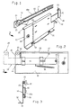
- Fig. 2 are the interacting parts of a roller pull-out guide 10 shown for drawers in which the Function of the drawer-side track in the - shown Case - made of metal by stamping and pressing Drawer side wall 12 is integrated.
- the on the associated guide rail 14 to be mounted on the body wall on the other hand, is conventional.
- the front end of the guide rail is then a second roller 24 rotatably mounted on which the drawer side wall 12 intended career of the drawer rolls.
- This career is in the case shown by one approximately at a right angle from the upper edge of the drawer side wall angled strip-shaped profile leg 26 formed, a lower one from the side facing away from the side wall strip-shaped profile leg 28 folded down which is on the one hand the roller 24 of the mounting rail encompasses the side facing away from the side and the other side stiffened upper edge of the drawer side wall and stabilized.
- a strip-shaped profile leg 30 in opposite Direction, i.e. away from the assigned body wall at right angles folded over, next to the stiffening of the side wall 12 at the same time to support the - not shown - Drawer bottom serves.
- profile leg 30 cut and edged, in a groove or recesses Serve in the drawer bottom rag 32 for fixing the drawer bottom on the profile leg 30.
- connection fitting arranged on which a second fitting part (not shown) can be fastened, that of the inner surface of an assigned drawer front panel steps forward. To the extent described so far the roller pull-out guide known.
- the slide member 38 settles in the case shown from a bearing plate 40 and one attached to the bearing plate flat elongated guide slide 42 together, which can be moved longitudinally on the parallel system Side wall 12 is held.
- the bearing plate 40 in turn is in the first retracted position in one to the inside of the body End and cutout 44 open at the top Drawer side wall 12 and it is dimensioned so that it this section in the retracted position of the slide component 38 fills in, the neckline also through an open to the back wall of the body, the bearing plate in the retracted position replaced matching receiving recess can be. If the bearing plate 40 to the level of the side wall arranged parallel offset on the guide slide 42 is the cutout 44 or the recess can also be omitted.
- the flat elongated guide slide 42 is on the to the outside of the side wall 12 facing the body wall held, being at least two in the pull-out direction the drawer spaced apart, the guide slide 42 fitting overlapping and on the side wall attached guide brackets 46a, 46b is guided.
- the screw 48 can be removed.
Landscapes
- Drawers Of Furniture (AREA)
Claims (10)
- Tiroir monté tirable dans le corps d'un meuble au moyen d'un guide de tirage à galet (10), sur chacune des parois latérales (12) duquel est prévu, dans la zone d'extrémité arrière intérieure au corps, au moins un galet (20) monté tournant autour d'un axe horizontal perpendiculaire à la direction de tirage et pouvant rouler sur des chemins de roulement (18a ; 18b) prévus sur un rail de guidage (14) pouvant être monté sur la paroi associée du corps, les rails de guidage (14) présentant chacun dans sa zone d'extrémité avant extérieure au corps au moins un galet (24) roulant sur un chemin de roulement (26) formé sur la paroi latérale associée (12) du tiroir, caractérisé par le fait que le galet (20) monté tournant sur la paroi latérale associée (12) du tiroir est placé dans la zone d'extrémité intérieure au corps d'un élément coulisseau (38) lui-même monté mobile longitudinalement sur la paroi latérale (12) d'une distance fixée dans la direction de tirage entre une position rentrée et une position sortie saillant de la paroi arrière du tiroir en direction de la paroi arrière du corps.
- Tiroir selon la revendication 1, caractérisé par le fait que chaque élément coulisseau (38) présente une plaque d'appui (40) placée dans une échancrure (44) ouverte vers l'extrémité intérieure au corps ou dans un creux de la paroi latérale (12), remplissant sensiblement juste l'échancrure (44) ou le creux et sur laquelle le galet (20) est monté tournant, et que sur la plaque d'appui (40) est monté un coulisseau de guidage plat (42) qui est monté mobile longitudinalement en appui parallèle sur la paroi latérale (12).
- Tiroir selon la revendication 2, caractérisé par le fait que le coulisseau de guidage (42) est tenu guidé sur la face extérieure dirigée vers la paroi du corps associée de la paroi latérale (12) correspondante.
- Tiroir selon la revendication 3, caractérisé par le fait que le coulisseau de guidage (42) est tenu par au moins deux étriers de guidage (46a ; 46b) espacés dans la direction de tirage du tiroir, coiffant juste le coulisseau de guidage (42) et fixés à la paroi latérale (12).
- Tiroir selon la revendication 4, caractérisé par le fait que le coulisseau de guidage (42) présente à son extrémité opposée à la plaque d'appui une butée qui fait saillie vers la paroi du corps et, dans la position tirée en arrière, vient s'appuyer contre l'étrier de guidage avant (46b).
- Tiroir selon la revendication 5, caractérisé par le fait que la butée est formée par la tête d'une vis (48) vissée par sa tige courte dans un trou taraudé fait dans le coulisseau de guidage (42).
- Tiroir selon l'une des revendications 1 et 2, caractérisé par le fait que le coulisseau de guidage (42) est guidé dans une moulure allongée dimensionnée à sa largeur et sa profondeur faite dans la paroi latérale (12) du tiroir.
- Tiroir selon l'une des revendications 1 à 7, caractérisé par le fait que sur l'élément coulisseau (38) agit directement ou indirectement un ressort en précontrainte (50) qui précontraint cet élément dans sa position rentrée dans laquelle la plaque d'appui (40) se trouve dans l'échancrure (44) de la paroi latérale (12).
- Tiroir selon la revendication 8, caractérisé par le fait que la force de précontrainte exercée par le ressort sur l'élément coulisseau (38) est supérieure aux forces de frottement entre l'élément coulisseau (38) et les éléments qui le tiennent mobile qui tendent à maintenir l'élément coulisseau (38) en position sortie.
- Tiroir selon l'une des revendications 8 et 9, caractérisé par un dispositif d'encliquetage qui maintient l'élément coulisseau (38) en position complètement sortie.
Applications Claiming Priority (2)
| Application Number | Priority Date | Filing Date | Title |
|---|---|---|---|
| DE19547685A DE19547685B4 (de) | 1995-12-20 | 1995-12-20 | Schublade mit Rollen-Ausziehführung |
| DE19547685 | 1995-12-20 |
Publications (3)
| Publication Number | Publication Date |
|---|---|
| EP0780071A2 EP0780071A2 (fr) | 1997-06-25 |
| EP0780071A3 EP0780071A3 (fr) | 2000-12-20 |
| EP0780071B1 true EP0780071B1 (fr) | 2002-11-13 |
Family
ID=7780729
Family Applications (1)
| Application Number | Title | Priority Date | Filing Date |
|---|---|---|---|
| EP96115103A Expired - Lifetime EP0780071B1 (fr) | 1995-12-20 | 1996-09-20 | Tiroir muni de glissière à billes |
Country Status (5)
| Country | Link |
|---|---|
| US (1) | US5733027A (fr) |
| EP (1) | EP0780071B1 (fr) |
| AT (1) | ATE227532T1 (fr) |
| DE (1) | DE19547685B4 (fr) |
| ES (1) | ES2181833T3 (fr) |
Families Citing this family (17)
| Publication number | Priority date | Publication date | Assignee | Title |
|---|---|---|---|---|
| DE19718256B4 (de) * | 1997-04-30 | 2005-02-24 | MEPLA-WERKE LAUTENSCHLäGER GMBH & CO. KG | Unterflur-Ausziehführung |
| US6027193A (en) * | 1999-02-26 | 2000-02-22 | Grass America, Inc. | Two-part undermount drawer guide assembly with pivot member |
| DE29923657U1 (de) * | 1999-09-17 | 2001-01-18 | Schock Metallwerk Gmbh, 73660 Urbach | Auszugführung |
| DE19944645A1 (de) * | 1999-09-17 | 2001-03-29 | Schock Metallwerk | Auszugführung |
| US20060082266A1 (en) * | 2000-05-01 | 2006-04-20 | Le Hai D | Self-moving slides and self-moving mechanisms |
| KR100473100B1 (ko) * | 2000-05-01 | 2005-03-10 | 어큐라이드 인터내셔널 인코포레이티드 | 자동 폐쇄식 슬라이드 및 자동 폐쇄식 슬라이드용 장치 |
| US6971729B1 (en) | 2000-05-01 | 2005-12-06 | Accuride International, Inc. | Self-closing slide |
| US6481812B1 (en) | 2000-09-19 | 2002-11-19 | Grass America, Inc. | Undermount drawer guide assembly |
| DE10227881A1 (de) * | 2002-06-22 | 2004-01-22 | Grass Gmbh | Schubladenführung |
| US7104691B2 (en) * | 2003-07-31 | 2006-09-12 | Accuride International, Inc. | Self-moving slide, mechanism for self-moving slide and method for self-moving a slide |
| USD492507S1 (en) | 2003-08-22 | 2004-07-06 | Suncast Corporation | Three drawer plastic cabinet |
| US20050168115A1 (en) * | 2004-02-04 | 2005-08-04 | Brian Moon | Drawer cabinet storage kit |
| US20050229360A1 (en) * | 2004-04-15 | 2005-10-20 | Lowe Mark J | Hinge |
| JP4763710B2 (ja) * | 2004-11-05 | 2011-08-31 | アキュライド インターナショナル,インコーポレイテッド | 自動性メカニズム及びこれを組み込むスライド |
| CN100556338C (zh) * | 2004-11-05 | 2009-11-04 | 艾库里德国际有限公司 | 阻尼移动机构及包括该机构的滑动装置 |
| US7533946B2 (en) * | 2005-08-25 | 2009-05-19 | Knape & Vogt Manufacturing Company | Closing device for drawers |
| US20070080614A1 (en) * | 2005-10-07 | 2007-04-12 | Suncast Corporation | Drawer cabinet storage kit |
Family Cites Families (11)
| Publication number | Priority date | Publication date | Assignee | Title |
|---|---|---|---|---|
| US883069A (en) * | 1905-03-16 | 1908-03-24 | Yawman & Erbe Mfg Co | Drawer-support for filing-cases. |
| US917885A (en) * | 1908-06-20 | 1909-04-13 | Morse Mfg Company | Drawer-support. |
| CH195282A (de) * | 1937-04-03 | 1938-01-31 | Union Kassenfabrik A G | Schrank mit in Führungen laufenden Schiebekörpern. |
| DE702934C (de) * | 1937-09-21 | 1941-02-24 | Buero Einrichtungs Fabriken Fo | dere fuer Bueromoebel |
| US2331529A (en) * | 1941-03-08 | 1943-10-12 | Remington Rand Inc | Drawer suspension |
| US2575566A (en) * | 1946-02-21 | 1951-11-20 | Shand Harold | Extensible side support for sliding drawers and the like |
| CH677435A5 (en) * | 1988-06-22 | 1991-05-31 | Fulterer Gmbh | Drawer extension mechanism - has ramp shoe on sliding rail and spring-loaded roller on fixed one |
| AT394133B (de) * | 1989-01-02 | 1992-02-10 | Blum Gmbh Julius | Schliessvorrichtung fuer in einem moebelkorpus angeordnete schubladen |
| AT399265B (de) * | 1991-12-11 | 1995-04-25 | Blum Gmbh Julius | Ausziehführung für schubladen |
| ATE134845T1 (de) * | 1991-12-06 | 1996-03-15 | Willach Gmbh Geb | Schubladenführung |
| DE29507853U1 (de) * | 1995-05-12 | 1995-07-27 | Paul Hettich Gmbh & Co., 32278 Kirchlengern | Kugel- und/oder Rollenauszugsführung für ein Möbelauszugsteil |
-
1995
- 1995-12-20 DE DE19547685A patent/DE19547685B4/de not_active Expired - Fee Related
-
1996
- 1996-09-20 AT AT96115103T patent/ATE227532T1/de not_active IP Right Cessation
- 1996-09-20 EP EP96115103A patent/EP0780071B1/fr not_active Expired - Lifetime
- 1996-09-20 ES ES96115103T patent/ES2181833T3/es not_active Expired - Lifetime
- 1996-11-20 US US08/752,534 patent/US5733027A/en not_active Expired - Fee Related
Also Published As
| Publication number | Publication date |
|---|---|
| DE19547685A1 (de) | 1997-06-26 |
| DE19547685B4 (de) | 2004-02-05 |
| ES2181833T3 (es) | 2003-03-01 |
| US5733027A (en) | 1998-03-31 |
| EP0780071A3 (fr) | 2000-12-20 |
| ATE227532T1 (de) | 2002-11-15 |
| EP0780071A2 (fr) | 1997-06-25 |
Similar Documents
| Publication | Publication Date | Title |
|---|---|---|
| EP0780071B1 (fr) | Tiroir muni de glissière à billes | |
| EP0701787B1 (fr) | Accessoire pour régler la hauteur de tiroirs | |
| DE3026544C2 (fr) | ||
| EP1845821B1 (fr) | Dispositif de fermeture et d'ouverture de tiroirs | |
| EP2916688B1 (fr) | Glissière télescopique de tiroir | |
| EP0694270B1 (fr) | Dispositif de guidage de tiroir à glissière double | |
| AT515690B1 (de) | Ausziehführung | |
| EP1110481B1 (fr) | Accessoire pour l'extraction complète de tiroirs et couplage | |
| WO1992013473A1 (fr) | Guide de sortie pour tiroirs | |
| EP3500133B1 (fr) | Étagère extractible pour placard | |
| DE2819099A1 (de) | Schubladenfuehrung | |
| AT505022A4 (de) | Schrank | |
| EP0957714B1 (fr) | Coulisse encastree de guidage de sortie pour tiroirs etc. | |
| EP0790022A2 (fr) | Glissière pour tiroirs placée sous le fond du tiroir | |
| EP0674863B1 (fr) | Dispositif de guidage pour tiroirs | |
| DE3923776C2 (fr) | ||
| EP2979581B1 (fr) | Dispositif de guidage pour le guidage d'une piece de meuble mobile par rapport a un corps de meuble | |
| DE212016000215U1 (de) | Schubladenausziehführung | |
| AT520805A1 (de) | Ausziehführung | |
| EP0855487B1 (fr) | Dispositif de guidage pour porte coulissante | |
| EP0809956A2 (fr) | Dispositif à tiroirs pour un élément coulissant, encastrable dans une unité d'armoire | |
| DE19706246B4 (de) | Teleskop-Schrankauszug | |
| DE9007404U1 (de) | Halterungsbeschlag für Schubladen-Ausziehführungen | |
| DE19911312B4 (de) | Ausziehführung | |
| AT400795B (de) | Schublade |
Legal Events
| Date | Code | Title | Description |
|---|---|---|---|
| PUAI | Public reference made under article 153(3) epc to a published international application that has entered the european phase |
Free format text: ORIGINAL CODE: 0009012 |
|
| AK | Designated contracting states |
Kind code of ref document: A2 Designated state(s): AT ES GB IT |
|
| PUAL | Search report despatched |
Free format text: ORIGINAL CODE: 0009013 |
|
| AK | Designated contracting states |
Kind code of ref document: A3 Designated state(s): AT ES GB IT |
|
| 17P | Request for examination filed |
Effective date: 20001110 |
|
| GRAG | Despatch of communication of intention to grant |
Free format text: ORIGINAL CODE: EPIDOS AGRA |
|
| GRAG | Despatch of communication of intention to grant |
Free format text: ORIGINAL CODE: EPIDOS AGRA |
|
| GRAH | Despatch of communication of intention to grant a patent |
Free format text: ORIGINAL CODE: EPIDOS IGRA |
|
| 17Q | First examination report despatched |
Effective date: 20020221 |
|
| GRAH | Despatch of communication of intention to grant a patent |
Free format text: ORIGINAL CODE: EPIDOS IGRA |
|
| GRAA | (expected) grant |
Free format text: ORIGINAL CODE: 0009210 |
|
| AK | Designated contracting states |
Kind code of ref document: B1 Designated state(s): AT ES GB IT |
|
| PG25 | Lapsed in a contracting state [announced via postgrant information from national office to epo] |
Ref country code: GB Free format text: LAPSE BECAUSE OF FAILURE TO SUBMIT A TRANSLATION OF THE DESCRIPTION OR TO PAY THE FEE WITHIN THE PRESCRIBED TIME-LIMIT Effective date: 20021113 |
|
| REF | Corresponds to: |
Ref document number: 227532 Country of ref document: AT Date of ref document: 20021115 Kind code of ref document: T |
|
| REG | Reference to a national code |
Ref country code: GB Ref legal event code: FG4D Free format text: NOT ENGLISH |
|
| REG | Reference to a national code |
Ref country code: ES Ref legal event code: FG2A Ref document number: 2181833 Country of ref document: ES Kind code of ref document: T3 |
|
| GBV | Gb: ep patent (uk) treated as always having been void in accordance with gb section 77(7)/1977 [no translation filed] |
Effective date: 20021113 |
|
| PLBE | No opposition filed within time limit |
Free format text: ORIGINAL CODE: 0009261 |
|
| STAA | Information on the status of an ep patent application or granted ep patent |
Free format text: STATUS: NO OPPOSITION FILED WITHIN TIME LIMIT |
|
| 26N | No opposition filed |
Effective date: 20030814 |
|
| PGFP | Annual fee paid to national office [announced via postgrant information from national office to epo] |
Ref country code: ES Payment date: 20070927 Year of fee payment: 12 |
|
| PGFP | Annual fee paid to national office [announced via postgrant information from national office to epo] |
Ref country code: AT Payment date: 20070907 Year of fee payment: 12 |
|
| PGFP | Annual fee paid to national office [announced via postgrant information from national office to epo] |
Ref country code: IT Payment date: 20070921 Year of fee payment: 12 |
|
| PG25 | Lapsed in a contracting state [announced via postgrant information from national office to epo] |
Ref country code: IT Free format text: LAPSE BECAUSE OF NON-PAYMENT OF DUE FEES Effective date: 20080920 Ref country code: AT Free format text: LAPSE BECAUSE OF NON-PAYMENT OF DUE FEES Effective date: 20080920 |
|
| REG | Reference to a national code |
Ref country code: ES Ref legal event code: FD2A Effective date: 20080922 |
|
| PG25 | Lapsed in a contracting state [announced via postgrant information from national office to epo] |
Ref country code: ES Free format text: LAPSE BECAUSE OF NON-PAYMENT OF DUE FEES Effective date: 20080922 |