EP0780276A2 - Bremsanlage für ein Kraftfahrzeug - Google Patents
Bremsanlage für ein Kraftfahrzeug Download PDFInfo
- Publication number
- EP0780276A2 EP0780276A2 EP96119030A EP96119030A EP0780276A2 EP 0780276 A2 EP0780276 A2 EP 0780276A2 EP 96119030 A EP96119030 A EP 96119030A EP 96119030 A EP96119030 A EP 96119030A EP 0780276 A2 EP0780276 A2 EP 0780276A2
- Authority
- EP
- European Patent Office
- Prior art keywords
- brake
- battery
- energy supply
- supply circuit
- motor vehicle
- Prior art date
- Legal status (The legal status is an assumption and is not a legal conclusion. Google has not performed a legal analysis and makes no representation as to the accuracy of the status listed.)
- Granted
Links
- 238000011161 development Methods 0.000 description 2
- 230000018109 developmental process Effects 0.000 description 2
- 238000010586 diagram Methods 0.000 description 1
- 230000000694 effects Effects 0.000 description 1
- 238000012423 maintenance Methods 0.000 description 1
- 230000007257 malfunction Effects 0.000 description 1
Images
Classifications
-
- B—PERFORMING OPERATIONS; TRANSPORTING
- B60—VEHICLES IN GENERAL
- B60T—VEHICLE BRAKE CONTROL SYSTEMS OR PARTS THEREOF; BRAKE CONTROL SYSTEMS OR PARTS THEREOF, IN GENERAL; ARRANGEMENT OF BRAKING ELEMENTS ON VEHICLES IN GENERAL; PORTABLE DEVICES FOR PREVENTING UNWANTED MOVEMENT OF VEHICLES; VEHICLE MODIFICATIONS TO FACILITATE COOLING OF BRAKES
- B60T13/00—Transmitting braking action from initiating means to ultimate brake actuator with power assistance or drive; Brake systems incorporating such transmitting means, e.g. air-pressure brake systems
- B60T13/10—Transmitting braking action from initiating means to ultimate brake actuator with power assistance or drive; Brake systems incorporating such transmitting means, e.g. air-pressure brake systems with fluid assistance, drive, or release
- B60T13/66—Electrical control in fluid-pressure brake systems
- B60T13/68—Electrical control in fluid-pressure brake systems by electrically-controlled valves
- B60T13/686—Electrical control in fluid-pressure brake systems by electrically-controlled valves in hydraulic systems or parts thereof
-
- B—PERFORMING OPERATIONS; TRANSPORTING
- B60—VEHICLES IN GENERAL
- B60T—VEHICLE BRAKE CONTROL SYSTEMS OR PARTS THEREOF; BRAKE CONTROL SYSTEMS OR PARTS THEREOF, IN GENERAL; ARRANGEMENT OF BRAKING ELEMENTS ON VEHICLES IN GENERAL; PORTABLE DEVICES FOR PREVENTING UNWANTED MOVEMENT OF VEHICLES; VEHICLE MODIFICATIONS TO FACILITATE COOLING OF BRAKES
- B60T13/00—Transmitting braking action from initiating means to ultimate brake actuator with power assistance or drive; Brake systems incorporating such transmitting means, e.g. air-pressure brake systems
- B60T13/74—Transmitting braking action from initiating means to ultimate brake actuator with power assistance or drive; Brake systems incorporating such transmitting means, e.g. air-pressure brake systems with electrical assistance or drive
-
- B—PERFORMING OPERATIONS; TRANSPORTING
- B60—VEHICLES IN GENERAL
- B60T—VEHICLE BRAKE CONTROL SYSTEMS OR PARTS THEREOF; BRAKE CONTROL SYSTEMS OR PARTS THEREOF, IN GENERAL; ARRANGEMENT OF BRAKING ELEMENTS ON VEHICLES IN GENERAL; PORTABLE DEVICES FOR PREVENTING UNWANTED MOVEMENT OF VEHICLES; VEHICLE MODIFICATIONS TO FACILITATE COOLING OF BRAKES
- B60T7/00—Brake-action initiating means
- B60T7/02—Brake-action initiating means for personal initiation
- B60T7/04—Brake-action initiating means for personal initiation foot actuated
- B60T7/042—Brake-action initiating means for personal initiation foot actuated by electrical means, e.g. using travel or force sensors
-
- B—PERFORMING OPERATIONS; TRANSPORTING
- B60—VEHICLES IN GENERAL
- B60T—VEHICLE BRAKE CONTROL SYSTEMS OR PARTS THEREOF; BRAKE CONTROL SYSTEMS OR PARTS THEREOF, IN GENERAL; ARRANGEMENT OF BRAKING ELEMENTS ON VEHICLES IN GENERAL; PORTABLE DEVICES FOR PREVENTING UNWANTED MOVEMENT OF VEHICLES; VEHICLE MODIFICATIONS TO FACILITATE COOLING OF BRAKES
- B60T8/00—Arrangements for adjusting wheel-braking force to meet varying vehicular or ground-surface conditions, e.g. limiting or varying distribution of braking force
- B60T8/32—Arrangements for adjusting wheel-braking force to meet varying vehicular or ground-surface conditions, e.g. limiting or varying distribution of braking force responsive to a speed condition, e.g. acceleration or deceleration
- B60T8/321—Arrangements for adjusting wheel-braking force to meet varying vehicular or ground-surface conditions, e.g. limiting or varying distribution of braking force responsive to a speed condition, e.g. acceleration or deceleration deceleration
- B60T8/3255—Systems in which the braking action is dependent on brake pedal data
-
- B—PERFORMING OPERATIONS; TRANSPORTING
- B60—VEHICLES IN GENERAL
- B60T—VEHICLE BRAKE CONTROL SYSTEMS OR PARTS THEREOF; BRAKE CONTROL SYSTEMS OR PARTS THEREOF, IN GENERAL; ARRANGEMENT OF BRAKING ELEMENTS ON VEHICLES IN GENERAL; PORTABLE DEVICES FOR PREVENTING UNWANTED MOVEMENT OF VEHICLES; VEHICLE MODIFICATIONS TO FACILITATE COOLING OF BRAKES
- B60T8/00—Arrangements for adjusting wheel-braking force to meet varying vehicular or ground-surface conditions, e.g. limiting or varying distribution of braking force
- B60T8/32—Arrangements for adjusting wheel-braking force to meet varying vehicular or ground-surface conditions, e.g. limiting or varying distribution of braking force responsive to a speed condition, e.g. acceleration or deceleration
- B60T8/34—Arrangements for adjusting wheel-braking force to meet varying vehicular or ground-surface conditions, e.g. limiting or varying distribution of braking force responsive to a speed condition, e.g. acceleration or deceleration having a fluid pressure regulator responsive to a speed condition
- B60T8/343—Systems characterised by their lay-out
-
- B—PERFORMING OPERATIONS; TRANSPORTING
- B60—VEHICLES IN GENERAL
- B60T—VEHICLE BRAKE CONTROL SYSTEMS OR PARTS THEREOF; BRAKE CONTROL SYSTEMS OR PARTS THEREOF, IN GENERAL; ARRANGEMENT OF BRAKING ELEMENTS ON VEHICLES IN GENERAL; PORTABLE DEVICES FOR PREVENTING UNWANTED MOVEMENT OF VEHICLES; VEHICLE MODIFICATIONS TO FACILITATE COOLING OF BRAKES
- B60T8/00—Arrangements for adjusting wheel-braking force to meet varying vehicular or ground-surface conditions, e.g. limiting or varying distribution of braking force
- B60T8/32—Arrangements for adjusting wheel-braking force to meet varying vehicular or ground-surface conditions, e.g. limiting or varying distribution of braking force responsive to a speed condition, e.g. acceleration or deceleration
- B60T8/34—Arrangements for adjusting wheel-braking force to meet varying vehicular or ground-surface conditions, e.g. limiting or varying distribution of braking force responsive to a speed condition, e.g. acceleration or deceleration having a fluid pressure regulator responsive to a speed condition
- B60T8/48—Arrangements for adjusting wheel-braking force to meet varying vehicular or ground-surface conditions, e.g. limiting or varying distribution of braking force responsive to a speed condition, e.g. acceleration or deceleration having a fluid pressure regulator responsive to a speed condition connecting the brake actuator to an alternative or additional source of fluid pressure, e.g. traction control systems
- B60T8/4809—Traction control, stability control, using both the wheel brakes and other automatic braking systems
-
- B—PERFORMING OPERATIONS; TRANSPORTING
- B60—VEHICLES IN GENERAL
- B60T—VEHICLE BRAKE CONTROL SYSTEMS OR PARTS THEREOF; BRAKE CONTROL SYSTEMS OR PARTS THEREOF, IN GENERAL; ARRANGEMENT OF BRAKING ELEMENTS ON VEHICLES IN GENERAL; PORTABLE DEVICES FOR PREVENTING UNWANTED MOVEMENT OF VEHICLES; VEHICLE MODIFICATIONS TO FACILITATE COOLING OF BRAKES
- B60T8/00—Arrangements for adjusting wheel-braking force to meet varying vehicular or ground-surface conditions, e.g. limiting or varying distribution of braking force
- B60T8/32—Arrangements for adjusting wheel-braking force to meet varying vehicular or ground-surface conditions, e.g. limiting or varying distribution of braking force responsive to a speed condition, e.g. acceleration or deceleration
- B60T8/88—Arrangements for adjusting wheel-braking force to meet varying vehicular or ground-surface conditions, e.g. limiting or varying distribution of braking force responsive to a speed condition, e.g. acceleration or deceleration with failure responsive means, i.e. means for detecting and indicating faulty operation of the speed responsive control means
- B60T8/885—Arrangements for adjusting wheel-braking force to meet varying vehicular or ground-surface conditions, e.g. limiting or varying distribution of braking force responsive to a speed condition, e.g. acceleration or deceleration with failure responsive means, i.e. means for detecting and indicating faulty operation of the speed responsive control means using electrical circuitry
-
- B—PERFORMING OPERATIONS; TRANSPORTING
- B60—VEHICLES IN GENERAL
- B60T—VEHICLE BRAKE CONTROL SYSTEMS OR PARTS THEREOF; BRAKE CONTROL SYSTEMS OR PARTS THEREOF, IN GENERAL; ARRANGEMENT OF BRAKING ELEMENTS ON VEHICLES IN GENERAL; PORTABLE DEVICES FOR PREVENTING UNWANTED MOVEMENT OF VEHICLES; VEHICLE MODIFICATIONS TO FACILITATE COOLING OF BRAKES
- B60T2270/00—Further aspects of brake control systems not otherwise provided for
- B60T2270/40—Failsafe aspects of brake control systems
- B60T2270/414—Power supply failure
-
- B—PERFORMING OPERATIONS; TRANSPORTING
- B60—VEHICLES IN GENERAL
- B60T—VEHICLE BRAKE CONTROL SYSTEMS OR PARTS THEREOF; BRAKE CONTROL SYSTEMS OR PARTS THEREOF, IN GENERAL; ARRANGEMENT OF BRAKING ELEMENTS ON VEHICLES IN GENERAL; PORTABLE DEVICES FOR PREVENTING UNWANTED MOVEMENT OF VEHICLES; VEHICLE MODIFICATIONS TO FACILITATE COOLING OF BRAKES
- B60T2270/00—Further aspects of brake control systems not otherwise provided for
- B60T2270/82—Brake-by-Wire, EHB
Definitions
- the invention relates to a brake system according to the preamble of claim 1.
- the brake signal actuated by the driver is separated from the brakes in terms of force, i. H.
- the braking torque request from the driver is no longer transmitted directly as a force via a hydraulic (or compressed air-operated) system, but only as an electrical signal via electrical lines.
- the electrical signal is used to control a brake actuator (or actuator) that generates the required braking torque with an independent energy supply.
- this energy supply comes from the electrical system and the braking torque is generated by an electromechanical or electrohydraulic actuator and transferred to a brake disc or drum (see the older application DE 19529664.8, our GR 95 P 1763 sign).
- the braking system Since the braking system represents a central safety function of the motor vehicle, it must ensure a high level of reliability and, in the event of a fault, at least enable the vehicle to be braked with reduced effectiveness. To this end, the legislation has issued a two-circuit braking system ensure, and in the event of a malfunction, at least with reduced effect, allow the vehicle to brake. For this purpose, the legislator requires a two-circuit brake system, which is usually implemented by two separate hydraulic brake circuits.
- Another known brake system has two separate electrical control circuits for two wheel brakes each. Both receive control signals from a device that detects the actuation of the brake pedal and each have their own energy supply circuit (GB 2 225 397 A). Additional braking functions serving the safety or comfort during the operation of the motor vehicle cannot be carried out with this system.
- control electronics are decentralized.
- a central module and several wheel modules each have microprocessors with their own Intelligence ".
- the wheel modules are hierarchically subordinate to the central module (EP 0 467 112 A).
- the circuitry and programming outlay is considerable.
- the invention has for its object to implement additional functions of the brakes with simple means.
- the advantages of the invention are in particular that the safety requirements to be placed on the brake system are met with little effort and simple means.
- the brake system according to the invention does not require any additional hydraulic emergency or replacement devices and no special fail-safe central control device for the normal braking function.
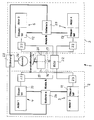
- Each wheel brake device consists of an actuator (actuator 1 to actuator 4) and an associated control part 10, 11, 12 and 13. Details of the actuators are not shown here, they can be electro-hydraulic (as described in our earlier application mentioned) or with be provided with an electromechanical drive (as in EP-B 0 486 281).
- a brake pedal 14 of the motor vehicle is a device - e.g. a braking force simulator 15 - connected, by the actuations of the brake pedal 14 are detected.
- the braking force simulator 15 contains two separate electronic sensor circuits 16 and 17, with which the pedal travel specified by the driver and / or the pedal force are measured. The measured variable is converted into control signals which are fed to brake circuit A via a first signal output line 19 and to brake circuit B via a second signal output line 20. These control signals represent the brake setpoints, they arrive at the wheel brake devices 4, 5 or 6, 7 and cause the associated actuators there to actuate the respective brakes.
- the brake system 1 thus carries out the braking operations desired by the driver of the motor vehicle and, since it is divided into two brake circuits, also corresponds to the required reliability.
- the brake system 1 also has an electronic control device or additional control device 22 (also referred to as an ECU) which only controls additional functions of the brakes, by means of which the safety and / or comfort of the motor vehicle are increased and which are already listed at the beginning (for example ABS, Traction control, etc.).
- additional control device 22 is not necessary.
- the control signals generated by the control device 22 reach electronic elements or switches 23, in which they are superimposed on the control signals or braking setpoints generated by the braking force simulator 14.
- This superimposition corresponds to the signal superimposition in hydraulic brake systems, but is very easy to implement with electronic elements.
- the elements 23 are constructed, for. B. as a relay that the control signals generated by the braking force simulator reach the wheel braking devices 4 to 7 in all cases even if the additional electronic control device 22 fails. In the event of a possible failure of the control device 22, only the additional functions of the brake system, such as. B. ABS, but not the normal braking function.
- the energy supply of the brake system 1 is also divided into two circuits, each of which contains a first battery a and a second battery b.
- the lines used for power supply are shown in the drawing with thick lines, while the signal lines are drawn with thin lines.
- the battery a the normal vehicle battery is used as the energy store 24 and 25, while in the case of the battery b an additional smaller battery which is adapted to the power requirement of the connected brake circuit is used.
- the generator 26 of the motor vehicle with a small battery as an emergency buffer, which has sufficient capacity for a few braking operations can also be used as the energy store 25.
- the two energy supply circuits are connected to one another via a fuse 28 which, in the event of a fault, for. B. in the event of a short circuit, completely separates both circuits.
- the following possible errors are absorbed by the brake system according to the invention: failure of the electronic control device 22 or an interruption of the electrical lines connected to it, a failure of one or two actuators, a failure of a power supply, an interruption of the connecting lines within the brake system and a short circuit in a supply circuit or in the generator 26.
- control parts 10 to 13 expediently contain a microprocessor, together with the respective actuator they form an independent unit. Details of the control are not shown here, since it is known per se and is not affected by the invention. If the control signals of the braking force simulator are transmitted as a pulse-width-modulated signal, the control part 10 to 13 is designed as a PWM output stage with electronic commutation.
- the brake system according to the invention represents a completely equivalent and powerful analogy to the usual two-circuit hydraulic brake systems with all additional functions. This is achieved with less effort and simpler means.
Landscapes
- Engineering & Computer Science (AREA)
- Transportation (AREA)
- Mechanical Engineering (AREA)
- Physics & Mathematics (AREA)
- Fluid Mechanics (AREA)
- Regulating Braking Force (AREA)
- Valves And Accessory Devices For Braking Systems (AREA)
- Braking Systems And Boosters (AREA)
Abstract
Description
- Die Erfindung betrifft eine Bremsanlage nach dem Oberbegriff von Anspruch 1.
- Personenkraftwagen sind heutzutage beinahe ausschließlich mit hydraulischen Bremsanlagen versehen. Steigende Anforderungen an zusätzliche Bremsfunktionen - wie Antiblockiersysteme, Fahrstabilitätsysteme, Traktionskontrollen und fortschrittliche Tempomaten - sowie Forderungen nach einer Verringerung der Montage- und Wartungskosten und einer Verkleinerung der Hydraulikeinrichtungen haben zu der Entwicklung rein elektrischer Bremssysteme (auch unter dem SchlagwortBrake by Wire" bekannt) geführt.

- Bei solchen elektrischen Bremssystemen ist das von dem Fahrer betätigte Bremssignal kraftmäßig von den Bremsen getrennt, d. h. die von dem Fahrer ausgehende Bremsmomentanforderung wird nicht mehr direkt als Kraft über ein hydraulisches (oder druckluftbetätigtes) System übertragen, sondern nur noch als elektrisches Signal über elektrische Leitungen. Mit dem elektrischen Signal wird ein Bremsaktuator (oder -aktor) gesteuert, der mit einer unabhängigen Energieversorgung das erforderliche Bremsmoment erzeugt. In der Regel erfolgt diese Energieversorgung aus dem elektrischen Bordnetz und das Bremsmoment wird durch einen elektromechanischen oder elektrohydraulischen Aktor erzeugt und auf eine Bremsscheibe oder -trommel übertragen (vgl. die ältere Anmeldung DE 19529664.8, unser Zeichen GR 95 P 1763).
- Da das Bremssystem eine zentrale Sicherheitsfunktion des Kraftfahrzeugs darstellt, muß es eine weitgehende Ausfallsicherheit gewährleisten, und im Störungsfall zumindest mit verringerter Wirkung ein Abbremsen des Fahrzeugs ermöglichen. Dazu wird vom Gesetzgeber ein zweikreisiges Bremssystem gecherheit gewährleisten, und im Störungsfall zumindest mit verringerter Wirkung ein Abbremsen des Fahrzeugs ermöglichen. Dazu wird vom Gesetzgeber ein zweikreisiges Bremssystem gefordert, das in der Regel durch zwei getrennte hydraulische Bremskreise realisiert ist.
- Bei einer bekannten Bremsanlage mit elektrisch gesteuerten Radbremseinrichtungen, die aus je einem Steuerteil und einem Aktor bestehen, durch die die einzelnen Radbremsen unabhängig voneinander und in Abhängigkeit von Betätigungen des Bremspedals aktiviert werden, ist ein Notfallsystem vorgesehen, durch das bei Ausfall eines oder mehrerer Aktoren ein Abbremsen des Kraftfahrzeugs ermöglicht wird (EP-A-0 486 281). Dabei werden fehlerhafte Aktoren erkannt und im Falle einer Bremsung die einwandfreien Aktoren oder einige von ihnen nach einem vorgegebenen Schema betätigt.
- Eine andere bekannte Bremsanlage weist zwei getrennte elektrische Steuerkreise für je zwei Radbremsen auf. Beide empfangen Steuersignale von einer Einrichtung, die Betätigungen des Bremspedals erfaßt und weisen je einen eigenen Energieversorgungskreis auf (GB 2 225 397 A). Zusätzliche, der Sicherheit oder dem Komfort beim Betrieb des Kraftfahrzeugs dienende Bremsfunktionen können mit dieser Anlage nicht ausgeführt werden.
- Bei einem weiteren bekannten Bremssystem ist die Steuerelektronik dezentral ausgebildet. Ein Zentralmodul und mehrere Radmodule weisen jeweils Mikroprozessoren mit eigenerIntelligenz" auf. Die Radmodule sind dem Zentralmodul hierarchisch unterstellt (EP 0 467 112 A). Der schaltungs- und programmtechnische Aufwand ist erheblich.
- Der Erfindung liegt die Aufgabe zugrunde, zusätzliche Funktionen der Bremsen mit einfachen Mitteln zu realisieren.
- Diese Aufgabe wird erfindungsgemäß durch die Bremsanlage nach Anspruch 1 gelöst. Zweckmäßige Weiterbildungen der Erfindung sind in den Unteransprüchen niedergelegt.
- Die Vorteile der Erfindung liegen insbesondere darin, daß die an die Bremsanlage zu stellenden Sicherheitsanforderungen mit geringem Aufwand und einfachen Mitteln erfüllt werden. Insbesondere benötigt die erfindungsgemäße Bremsanlage keinerlei zusätzliche hydraulische Notfall- oder Ersatzeinrichtungen und kein besonderes ausfallgesichertes zentrales Steuergerät für die normale Bremsfunktion.
- Ein Ausführungsbeispiel der Erfindung wird im folgenden anhand der Zeichnung erläutert. Die einzige Figur zeigt eine Bremsanlage gemäß der Erfindung in Blockdiagrammdarstellung.
- bremseinrichtungen 4, 5, 6 und 7 von denen die Radbremseinrichtungen 4 und 5 Bestandteil des Bremskreises A und die Radbremseinrichtungen 6, 7 Bestandteile des Bremskreises B sind.
- Jede Radbremseinrichtung besteht aus einem Aktor (Aktor 1 bis Aktor 4) und einem zugehörigen Steuerteil 10, 11, 12 bzw. 13. Einzelheiten der Aktoren sind hier nicht dargestellt, sie können elektrohydraulisch ausgebildet sein (wie in unserer vorgenannten älteren Anmeldung beschrieben) oder mit einem elektromechanischen Antrieb versehen sein, (wie in der EP-B 0 486 281).
- Mit einem Bremspedal 14 des Kraftfahrzeugs ist eine Einrichtung - z.B. ein Bremskraftsimulator 15 - verbunden, durch die Betätigungen des Bremspedals 14 erfaßt werden. Der Bremskraftsimulator 15 enthält zwei getrennte elektronische Sensorkreise 16 und 17, mit denen der vom Fahrer vorgegebene Pedalweg und/oder die Pedalkraft gemessen werden. Die gemessene Größe wird in Steuersignale umgesetzt, die über eine erste Signalausgangsleitung 19 dem Bremskreis A und über eine zweite Signalausgangsleitung 20 dem Bremskreis B zugeführt werden. Diese Steuersignale stellen die Bremssollwerte dar, sie gelangen zu den Radbremseinrichtungen 4, 5 bzw. 6, 7 und veranlassen dort die zugehörigen Aktoren, die jeweiligen Bremsen zu betätigen. Damit führt die Bremsanlage 1 die von dem Fahrer des Kraftfahrzeugs gewünschten Bremsungen durch, und sie entspricht auch, da sie in zwei Bremskreise aufgeteilt ist, der geforderten Ausfallsicherheit.
- Die Bremsanlage 1 weist außerdem eine elektronische Steuereinrichtung - oder Zusatzsteuereinrichtung 22 (auch als ECU bezeichnet) auf, die lediglich zusätzliche Funktionen der Bremsen steuert, durch die die Sicherheit und/oder Komfort des Kraftfahrzeugs erhöht werden und die eingangs schon aufgeführt sind (z.B. ABS, Traktionskontrolle usw.). Für eine ausfallsichere Funktion der erfindungsgemäßen Bremsanlage 1 ist die Zusatzsteuereinrichtung 22 nicht notwendig.
- Die von der Steuereinrichtung 22 erzeugten Steuersignale gelangen zu elektronischen Elementen oder Schaltern 23, in denen sie den vom Bremskraftsimulator 14 erzeugten Steuersignalen oder Bremssollwerten überlagert werden. Diese Überlagerung entspricht der Signalüberlagerung in hydraulischen Bremsanlagen, ist aber mit elektronischen Elementen sehr einfach zu realisieren. Die Elemente 23 sind so aufgebaut, z. B. als Relais, daß die vom Bremskraftsimulator erzeugten Steuersignale auch bei einem Ausfall der zusätzlichen elektronischen Steuereinrichtung 22 in allen Fällen zu den Radbremseinrichtungen 4 bis 7 gelangen. Bei einem möglichen Ausfall der Steuereinrichtung 22 werden nur die Zusatzfunktionen der Bremsanlage, wie z. B. ABS, beeinträchtigt, nicht aber die normale Bremsfunktion.
- Die Energieversorgung der Bremsanlage 1 ist ebenfalls in zwei Kreise unterteilt, die jeweils eine erste Batterie a und eine zweite Batterie b enthalten. Die der Energieversorgung dienenden Leitungen sind in der Zeichnung mit dicken Linien dargestellt, während die Signalleitungen mit dünnen Linien gezeichnet sind. Als Energiespeicher 24 und 25 dient im Falle der Batterie a die normale Fahrzeugbatterie, während im Falle der Batterie b eine zusätzliche kleinere, dem Leistungsbedarf des angeschlossenen Bremskreises angepaßte Batterie verwendet wird. Anstelle der Batterie b kann als Energiespeicher 25 auch der Generator 26 des Kraftfahrzeugs mit einer kleinen Batterie als Notfallpuffer verwendet werden, die für einige wenige Bremsvorgänge ausreichend Kapazität hat. Die beiden Energieversorgungskreise sind über eine Sicherung 28 miteinander verbunden, die im Fehlerfall, z. B. bei einem Kurzschluß, beide Kreis vollständig voneinander trennt.
- Durch die erfindungsgemäße Bremsanlage werden folgende mögliche Fehler aufgefangen: ein Ausfall der elektronischen Steuereinrichtung 22 oder eine Unterbrechung der mit ihr verbundenen elektrischen Leitungen, ein Ausfall eines oder zweier Aktoren, ein Ausfall einer Energieversorgung, eine Unterbrechung der Verbindungsleitungen innerhalb der Bremsanlage und ein Kurzschluß in einem Versorgungskreis oder in dem Generator 26.
- Die Steuerteile 10 bis 13 enthalten zweckmäßigerweise einen Mikroprozessor, sie bilden zusammen mit dem jeweiligen Aktor eine selbständige Einheit. Einzelheiten der Steuerung sind hier nicht dargestellt, da sie für sich bekannt ist und von der Erfindung nicht berührt wird. Werden die Steuersignale des Bremskraftsimulators als pulsweitenmoduliertes Signal übertragen, so wird das Steuerteil 10 bis 13 als PWM-Endstufe mit elektronischer Kommutierung ausgeführt.
- Die erfindungsgemäße Bremsanlage stellt eine völlig gleichwertige und leistungsfähige Analogie zu den üblichen zweikreisigen hydraulischen Bremsanlagen mit allen Zusatzfunktionen dar. Dies wird aber mit geringerem Aufwand und einfacheren Mitteln erreicht.
Claims (4)
- Bremsanlage (1) für ein Kraftfahrzeug mit elektrisch gesteuerten Radbremseinrichtungen (4-7), die aus je einem Steuerteil (10-13) und einem Aktor bestehen, durch die die einzelnen Radbremsen unabhängig voneinander und in Abhängigkeit von Betätigungen des Bremspedals aktiviert werden, und mit zwei getrennten elektrischen Steuerkreisen (2, 3), die für je einen Teil der Radbremseinrichtungen (4-7) vorgesehen sind, die beide von einer Betätigungen des Bremspedals (14) erfassenden Einrichtung (15) Steuersignale empfangen und die je eine eigenen Energieversorgungskreis (a, b) aufweisen, so daß auch bei Ausfall eines oder mehrerer Aktoren ein Abbremsen des Kraftfahrzeugs möglich ist, dadurch gekennzeichnet, daß sie eine zusätzliche zentrale Steuereinrichtung (22) aufweist, die mit allen Radbremseinrichtungen (4-7) verbunden ist und durch die der Sicherheit oder dem Komfort des Kraftfahrzeugs dienende Bremsfunktionen gesteuert werden.
- Bremsanlage nach Anspruch 1, dadurch gekennzeichnet, daß ein erster Energieversorgungskreis von der Fahrzeugbatterie (Batterie a) und ein zweiter Energieversorgungskreis von einer Zusatzbatterie (Batterie b) mit einer an den Leistungsbedarf des Bremskreises angepaßten Kapazität gespeist wird.
- Bremsanlage nach Anspruch 1, dadurch gekennzeichnet, daß ein erster Energieversorgungskreis von der Fahrzeugbatterie (Batterie a) und ein zweiter Energieversorgungskreis von dem Generator (26) des Kraftfahrzeugs und einer Zusatzbatterie mit einer für einige Bremsungen genügenden Kapazität gespeist wird.
- Bremsanlage nach Anspruch 1, dadurch gekennzeichnet, daß die Steuerteile (10-13) für die Aktoren mikroprozessorgesteuert sind.
Applications Claiming Priority (2)
| Application Number | Priority Date | Filing Date | Title |
|---|---|---|---|
| DE19548392 | 1995-12-22 | ||
| DE19548392A DE19548392C2 (de) | 1995-12-22 | 1995-12-22 | Bremsanlage für ein Kraftfahrzeug |
Publications (3)
| Publication Number | Publication Date |
|---|---|
| EP0780276A2 true EP0780276A2 (de) | 1997-06-25 |
| EP0780276A3 EP0780276A3 (de) | 2000-03-15 |
| EP0780276B1 EP0780276B1 (de) | 2003-06-11 |
Family
ID=7781183
Family Applications (1)
| Application Number | Title | Priority Date | Filing Date |
|---|---|---|---|
| EP96119030A Expired - Lifetime EP0780276B1 (de) | 1995-12-22 | 1996-11-27 | Bremsanlage für ein Kraftfahrzeug |
Country Status (5)
| Country | Link |
|---|---|
| US (1) | US5961190A (de) |
| EP (1) | EP0780276B1 (de) |
| KR (1) | KR970040606A (de) |
| DE (2) | DE19548392C2 (de) |
| ES (1) | ES2201148T3 (de) |
Cited By (12)
| Publication number | Priority date | Publication date | Assignee | Title |
|---|---|---|---|---|
| WO1998039189A1 (de) * | 1997-03-05 | 1998-09-11 | Mannesmann Rexroth Ag | Elektrisch gesteuertes bremssystem für ein radfahrzeug |
| FR2766779A1 (fr) * | 1997-07-30 | 1999-02-05 | Siemens Ag | Systeme de freinage pour vehicule automobile |
| GB2338763A (en) * | 1998-02-16 | 1999-12-29 | Siemens Ag | Brake system for a motor vehicle |
| DE102004059546A1 (de) * | 2004-12-09 | 2006-06-22 | Lucas Automotive Gmbh | Elektronisches System zum Betreiben einer elektromechanischen Feststell-Bremsanlage |
| EP1832482A2 (de) | 1999-02-03 | 2007-09-12 | Toyota Jidosha Kabushiki Kaisha | Bremssystem mit Schaltvorrichtung zur Energieversorgung einer elektrisch gesteuerten Bremse durch ein Bremssteuergerät bei Betätigung eines Bremsbetätigungselements |
| FR2901212A1 (fr) * | 2006-05-18 | 2007-11-23 | Renault Sas | Installation electrique pour vehicule automobile |
| WO2008074649A1 (de) * | 2006-12-19 | 2008-06-26 | Robert Bosch Gmbh | Datenverarbeitungssystem für ein kraftfahrzeug |
| WO2009074252A1 (de) * | 2007-12-12 | 2009-06-18 | Lucas Automotive Gmbh | Elektronisches system zum betreiben einer elektromechanischen parkbremse |
| FR2939749A1 (fr) * | 2008-12-16 | 2010-06-18 | Renault Sas | Systeme de liaison entre organes et capteurs de vehicule automobile a commandes electriques |
| WO2018073038A1 (de) * | 2016-10-20 | 2018-04-26 | Lucas Automotive Gmbh | System mit getrennten steuereinheiten für die stelleinheiten einer elektrischen parkbremse |
| WO2018108351A1 (de) * | 2016-12-14 | 2018-06-21 | Robert Bosch Gmbh | Verfahren zur ansteuerung eines hydraulischen bremssystems in einem fahrzeug |
| DE102023122197A1 (de) | 2022-10-11 | 2024-04-11 | Zf Active Safety Gmbh | Dezentrales Steuersystem für eine Kraftfahrzeug-Bremsanlage, Kraftfahrzeug-Bremsanlage und Kraftfahrzeug |
Families Citing this family (77)
| Publication number | Priority date | Publication date | Assignee | Title |
|---|---|---|---|---|
| DE19634567B4 (de) * | 1996-08-27 | 2007-11-29 | Robert Bosch Gmbh | Elektrisches Bremssystem |
| US6227626B1 (en) * | 1996-09-19 | 2001-05-08 | Robert Bosch Gmbh | Method and device for controlling a motor vehicle drive train |
| DE19827455C2 (de) * | 1997-07-30 | 2000-03-16 | Siemens Ag | Bremsanlage für ein Kraftfahrzeug |
| GB2357818B (en) * | 1997-07-30 | 2001-10-10 | Siemens Ag | Brake system for a motor vehicle |
| DE19861095C2 (de) * | 1997-07-30 | 2001-04-12 | Siemens Ag | Bremsanlage für ein Kraftfahrzeug |
| DE19743305C2 (de) * | 1997-09-30 | 2001-03-15 | Siemens Ag | Anordnung zur Sicherstellung des Lösens einer selbsthemmenden Bremse während eines Bremsvorgangs eines Fahrzeugs |
| DE19747093C2 (de) * | 1997-10-24 | 2002-10-17 | Siemens Ag | Elektrisch betätigte Bremsanlage |
| EP1031182B1 (de) * | 1997-11-21 | 2004-02-18 | Continental Teves AG & Co. oHG | Verfahren und schaltungsanordnung zur erzeugung eines pulsbreitenmodulierten stellsignals für einen gleichstromaktuator |
| US6345225B1 (en) | 1997-11-22 | 2002-02-05 | Continental Teves Ag & Co., Ohg | Electromechanical brake system |
| DE19829126A1 (de) * | 1997-11-22 | 1999-05-27 | Itt Mfg Enterprises Inc | Elektromechanisches Bremssystem |
| DE19752543A1 (de) * | 1997-11-27 | 1999-06-02 | Bosch Gmbh Robert | Magnetbremse und elektromechanische Bremsvorrichtung mit einer Magnetbremse |
| US6213567B1 (en) * | 1998-02-02 | 2001-04-10 | Siemens Aktiengesellschaft | Brake system for a motor vehicle and method for transmitting data in an electrically controlled brake system for a motor vehicle |
| DE19841335A1 (de) * | 1998-02-07 | 1999-08-12 | Itt Mfg Enterprises Inc | Generierung eines Bremswunsches für die Steuerung der elektrischen Bremsanlage |
| DE19815440A1 (de) * | 1998-04-07 | 1999-10-14 | Wabco Gmbh | Steuereinrichtung für eine Fahrzeug-Bremsanlage |
| DE19826131A1 (de) * | 1998-06-12 | 1999-12-16 | Bosch Gmbh Robert | Elektrisches Bremssystem für ein Kraftfahrzeug |
| DE19826687A1 (de) * | 1998-06-16 | 1999-12-23 | Continental Teves Ag & Co Ohg | Elektrisch betätigbares Bremssystem für Kraftfahrzeuge und Verfahren zu seiner Ansteuerung |
| DE19828331C1 (de) * | 1998-06-25 | 2000-03-02 | Continental Ag | Verfahren zum Betreiben einer elektromechanischen Bremsanlage |
| DE19835352C1 (de) * | 1998-08-05 | 2000-04-20 | Daimler Chrysler Ag | Brems- und/oder Fahrwerkregelvorrichtung |
| DE19860645A1 (de) * | 1998-12-29 | 2000-07-06 | Bosch Gmbh Robert | Verfahren und Vorrichtung zur Steuerung des Antriebsstrangs eines Fahrzeugs |
| US6296325B1 (en) | 1999-07-15 | 2001-10-02 | The B. F. Goodrich Company | Method to connect and distribute power to an electromechanical braking system |
| US6402259B2 (en) * | 1999-07-14 | 2002-06-11 | Goodrich Corporation | Electromechanical braking system with power distribution and redundancy |
| JP3872242B2 (ja) * | 1999-09-21 | 2007-01-24 | トヨタ自動車株式会社 | ブレーキ制御装置 |
| DE19960611B4 (de) * | 1999-12-09 | 2009-10-22 | Volkswagen Ag | Elektromechanische Bremsanlage |
| WO2001062569A1 (en) * | 2000-02-24 | 2001-08-30 | Delphi Technologies, Inc. | Brake by wire electrical system architecture with multiple power sources and circuit protection |
| US6412880B1 (en) * | 2000-03-29 | 2002-07-02 | Honeywell Commercial Vehicle Systems Co. | Combined power supply and electronic control circuit for ABS |
| US6390571B1 (en) | 2000-06-29 | 2002-05-21 | Goodrich Corporation | Redundant aircraft braking system architecture |
| FR2816583B1 (fr) * | 2000-11-10 | 2003-02-21 | Messier Bugatti | Architecture de systeme hydraulique de freinage d'aeronef |
| DE10061054A1 (de) * | 2000-12-08 | 2002-07-04 | Knorr Bremse Systeme | Fußbremsmodul mit Wake-up Funktion |
| DE10106378C2 (de) * | 2001-02-12 | 2003-03-06 | Knorr Bremse Systeme | Elektromechanische Bremszuspanneinrichtung |
| JP4396066B2 (ja) * | 2001-08-07 | 2010-01-13 | 株式会社日立製作所 | 電動ブレーキ装置 |
| DE10223880B4 (de) * | 2002-05-29 | 2004-06-17 | Robert Bosch Gmbh | Verfahren zur gegenseitigen Überwachung von Komponenten eines dezentral verteilten Rechnersystems |
| US6997521B2 (en) | 2002-09-06 | 2006-02-14 | Caterpillar Inc. | Parking and service brake control system for a vehicle |
| DE10245207C1 (de) * | 2002-09-27 | 2003-10-23 | Knorr Bremse Systeme | Bremszuspanneinrichtung |
| FR2845057B1 (fr) * | 2002-10-01 | 2004-11-26 | Renault Sa | Procede de freinage electrique pour vehicule |
| US7359786B2 (en) * | 2003-09-29 | 2008-04-15 | Haldex Brake Products Ab | Control and power supply network for vehicle braking system |
| US7150506B2 (en) † | 2003-09-29 | 2006-12-19 | Haldex Brake Products Ab | Control network for brake system |
| US7396088B2 (en) * | 2003-09-29 | 2008-07-08 | Haldex Brake Products Ab | Power supply network for brake system |
| FR2862942B1 (fr) * | 2003-12-01 | 2006-03-03 | Messier Bugatti | Procede de gestion d'une architecture de systeme de freinage pour aeronef equipe de freins a actionneurs electromecaniques, et architecture faisant application |
| DE102004009466A1 (de) * | 2004-02-27 | 2005-09-15 | Daimlerchrysler Ag | Bremssteuerungssystem für ein Fahrzeug |
| US7258404B2 (en) * | 2004-11-11 | 2007-08-21 | Hydro-Aire, Inc. | Antiskid control-combined paired/individual wheel control logic |
| US20080135357A1 (en) * | 2004-11-29 | 2008-06-12 | Hans Lang | Electromechanical Braking System |
| WO2007107576A1 (fr) * | 2006-03-23 | 2007-09-27 | Michelin Recherche Et Technique S.A. | Système de freinage électrique d'un véhicule routier, à contrôle totalement électrique |
| FR2902709B1 (fr) * | 2006-06-26 | 2008-09-05 | Conception & Dev Michelin Sa | Architecture materielle redondante pour l'etage de signaux de commande d'un systeme de freinage d'un vehicule dont toutes les roues sont reliees chacune a au moins une machine electrique rotative |
| FR2902707B1 (fr) * | 2006-06-26 | 2008-09-05 | Conception & Dev Michelin Sa | Architecture materielle rebondante pour etage d'alimentation basse tension d'un systeme de freinage d'un vehicule dont toutes les roues sont reliees chacune a au moins une machine electrique rotative |
| FR2902708B1 (fr) * | 2006-06-26 | 2015-03-27 | Conception & Dev Michelin Sa | Architecture materielle redondante pour l'etage de puissance d'un systeme de freinage d'un vehicule dont toutes les roues sont reliees chacune a au moins une machine electrique rotative |
| GB0705789D0 (en) * | 2007-03-26 | 2007-05-02 | Haldex Brake Products Ltd | Vehicle braking system |
| US7837278B2 (en) * | 2007-05-30 | 2010-11-23 | Haldex Brake Products Ab | Redundant brake actuators for fail safe brake system |
| FR2921310B1 (fr) * | 2007-09-20 | 2011-04-29 | Michelin Soc Tech | Architecture materielle redondante pour l'etage de signaux de commande d'un systeme de freinage d'un vehicule dont toutes les roues sont reliees chacune a au moins une machine electrique rotative |
| KR20100007504A (ko) * | 2008-07-14 | 2010-01-22 | 주식회사 만도 | 차량용 제동 시스템 |
| US20100025167A1 (en) * | 2008-07-31 | 2010-02-04 | Caterpillar Inc. | Braking system for an off-highway machine involving electric retarding integrated with service brakes |
| US8281908B2 (en) * | 2008-08-29 | 2012-10-09 | Caterpillar Inc. | Brake cooling fluid diverter for an off-highway machine |
| US7996163B2 (en) | 2008-09-15 | 2011-08-09 | Caterpillar Inc. | Method and apparatus for detecting a short circuit in a DC link |
| US8140206B2 (en) | 2008-09-15 | 2012-03-20 | Caterpillar Inc. | Engine load management for traction vehicles |
| US9063202B2 (en) | 2008-09-15 | 2015-06-23 | Caterpillar Inc. | Method and apparatus for detecting phase current imbalance in a power generator |
| US7918296B2 (en) | 2008-09-15 | 2011-04-05 | Caterpillar Inc. | Cooling system for an electric drive machine and method |
| US8324846B2 (en) | 2008-09-15 | 2012-12-04 | Caterpillar Inc. | Electric drive retarding system and method |
| US7795825B2 (en) | 2008-09-15 | 2010-09-14 | Caterpillar Inc | Over-voltage and under-voltage management for electric drive system |
| US7956762B2 (en) * | 2008-09-15 | 2011-06-07 | Caterpillar Inc. | Method and apparatus for power generation failure diagnostics |
| US8410739B2 (en) * | 2008-09-15 | 2013-04-02 | Caterpillar Inc. | Method and apparatus for determining the operating condition of generator rotating diodes |
| US8253357B2 (en) | 2008-09-15 | 2012-08-28 | Caterpillar Inc. | Load demand and power generation balancing in direct series electric drive system |
| US8054016B2 (en) | 2008-09-15 | 2011-11-08 | Caterpillar Inc. | Retarding energy calculator for an electric drive machine |
| JP5163807B2 (ja) * | 2010-03-18 | 2013-03-13 | トヨタ自動車株式会社 | マイコン相互監視システム及びマイコン相互監視方法 |
| US8626368B2 (en) | 2010-09-07 | 2014-01-07 | Caterpillar Inc. | Electric drive power response management system and method |
| US20120198959A1 (en) * | 2011-01-11 | 2012-08-09 | Ipgate Ag | Travel simulator arrangement |
| US9083202B2 (en) * | 2012-12-18 | 2015-07-14 | Fca Us Llc | Alternator control for battery charging |
| JP6565388B2 (ja) * | 2015-07-02 | 2019-08-28 | 三菱自動車工業株式会社 | 電動ブレーキ装置 |
| DE102015217708A1 (de) | 2015-09-16 | 2017-03-16 | Continental Teves Ag & Co. Ohg | Bremsanlage für Kraftfahrzeuge |
| US10549731B2 (en) * | 2015-12-10 | 2020-02-04 | Ford Global Technologies, Llc | Electric parking brake for autonomous vehicles |
| US10144402B2 (en) * | 2016-08-29 | 2018-12-04 | GM Global Technology Operations LLC | Brake-by-wire system |
| DE102017102074A1 (de) * | 2017-02-02 | 2018-08-02 | Knorr-Bremse Systeme für Nutzfahrzeuge GmbH | Schnittstellenelement für ein Fahrzeug |
| DE102018206075A1 (de) * | 2018-04-20 | 2019-10-24 | Robert Bosch Gmbh | Vorrichtung und Verfahren zum Bremsen und Nothalt eines Fahrzeugs |
| DE102020107706A1 (de) | 2020-03-20 | 2021-09-23 | HELLA GmbH & Co. KGaA | Bremssystem und Fahrzeug mit dem Bremssystem |
| DE102020204102A1 (de) | 2020-03-30 | 2021-09-30 | Continental Teves Ag & Co. Ohg | Bremssystem |
| EP3939841B1 (de) * | 2020-07-17 | 2026-03-25 | KNORR-BREMSE Systeme für Nutzfahrzeuge GmbH | Aktuator für eine radbremseinheit eines fahrzeugs |
| WO2022165636A1 (zh) * | 2021-02-02 | 2022-08-11 | 智马达汽车有限公司 | 一种冗余电子驻车制动系统、控制方法及车辆 |
| DE102022209930A1 (de) * | 2022-09-21 | 2024-03-21 | Continental Automotive Technologies GmbH | Bremssystem mit flexibler Architektur und Verfahren zum Betreiben eines derartigen Bremssystems |
| DE102024100205A1 (de) * | 2024-01-04 | 2025-07-10 | Audi Aktiengesellschaft | Bremsanlage für ein zweispuriges Fahrzeug |
Citations (3)
| Publication number | Priority date | Publication date | Assignee | Title |
|---|---|---|---|---|
| GB2225397A (en) | 1988-11-09 | 1990-05-30 | Automotive Products Plc | Electrical control of braking |
| EP0467112A2 (de) | 1990-07-17 | 1992-01-22 | WABCO GmbH | Elektronisches Bremssystem für Strassenfahrzeuge |
| EP0486281A1 (de) | 1990-11-13 | 1992-05-20 | Honda Giken Kogyo Kabushiki Kaisha | Kraftfahrzeugbremssystem mit Ausfallsicherung |
Family Cites Families (9)
| Publication number | Priority date | Publication date | Assignee | Title |
|---|---|---|---|---|
| US3792742A (en) * | 1972-02-08 | 1974-02-19 | C Mager | Electric motor operated vehicle |
| HU178550B (en) * | 1978-04-22 | 1982-05-28 | Girling Ltd | Non-skid brake mechanism for multiple-axle wheeled vehicles |
| US4300088A (en) * | 1979-04-13 | 1981-11-10 | Hicks David E | Electric charging apparatus for ground vehicles |
| US4326236A (en) * | 1979-09-10 | 1982-04-20 | Baylor Company | Control system for an electro-magnetic brake |
| GB8623988D0 (en) * | 1986-10-07 | 1986-11-12 | Bendix Ltd | Vehicle braking systems |
| US5288139A (en) * | 1992-06-05 | 1994-02-22 | Allied-Signal Inc. | Electropneumatic braking system |
| DE4335769C1 (de) * | 1993-10-20 | 1994-12-08 | Daimler Benz Ag | Bremsdruck-Steuereinrichtung für ein Straßenfahrzeug |
| DE19509150C2 (de) * | 1995-03-14 | 2003-03-27 | Continental Teves Ag & Co Ohg | Verfahren zum Steuern und Regeln von Fahrzeug-Bremsanlagen sowie Fahrzeug-Bremsanlage |
| DE19529664A1 (de) * | 1995-08-11 | 1997-02-13 | Siemens Ag | Bremsanlage für ein Kraftfahrzeug |
-
1995
- 1995-12-22 DE DE19548392A patent/DE19548392C2/de not_active Expired - Fee Related
-
1996
- 1996-11-27 ES ES96119030T patent/ES2201148T3/es not_active Expired - Lifetime
- 1996-11-27 DE DE59610526T patent/DE59610526D1/de not_active Expired - Fee Related
- 1996-11-27 EP EP96119030A patent/EP0780276B1/de not_active Expired - Lifetime
- 1996-12-20 KR KR1019960068816A patent/KR970040606A/ko not_active Withdrawn
- 1996-12-23 US US08/779,969 patent/US5961190A/en not_active Expired - Lifetime
Patent Citations (4)
| Publication number | Priority date | Publication date | Assignee | Title |
|---|---|---|---|---|
| GB2225397A (en) | 1988-11-09 | 1990-05-30 | Automotive Products Plc | Electrical control of braking |
| EP0467112A2 (de) | 1990-07-17 | 1992-01-22 | WABCO GmbH | Elektronisches Bremssystem für Strassenfahrzeuge |
| EP0486281A1 (de) | 1990-11-13 | 1992-05-20 | Honda Giken Kogyo Kabushiki Kaisha | Kraftfahrzeugbremssystem mit Ausfallsicherung |
| EP0486281B1 (de) | 1990-11-13 | 1995-04-26 | Honda Giken Kogyo Kabushiki Kaisha | Kraftfahrzeugbremssystem mit Ausfallsicherung |
Cited By (22)
| Publication number | Priority date | Publication date | Assignee | Title |
|---|---|---|---|---|
| US6209966B1 (en) | 1997-03-05 | 2001-04-03 | Mannesmann Rexroth Ag | Electrically controlled braking system for a wheeled vehicle |
| WO1998039189A1 (de) * | 1997-03-05 | 1998-09-11 | Mannesmann Rexroth Ag | Elektrisch gesteuertes bremssystem für ein radfahrzeug |
| FR2766779A1 (fr) * | 1997-07-30 | 1999-02-05 | Siemens Ag | Systeme de freinage pour vehicule automobile |
| GB2338763A (en) * | 1998-02-16 | 1999-12-29 | Siemens Ag | Brake system for a motor vehicle |
| GB2338763B (en) * | 1998-02-16 | 2001-11-21 | Siemens Ag | Brake system for a motor vehicle |
| EP1832482A3 (de) * | 1999-02-03 | 2008-07-23 | Toyota Jidosha Kabushiki Kaisha | Bremssystem mit Schaltvorrichtung zur Energieversorgung einer elektrisch gesteuerten Bremse durch ein Bremssteuergerät bei Betätigung eines Bremsbetätigungselements |
| EP1832482A2 (de) | 1999-02-03 | 2007-09-12 | Toyota Jidosha Kabushiki Kaisha | Bremssystem mit Schaltvorrichtung zur Energieversorgung einer elektrisch gesteuerten Bremse durch ein Bremssteuergerät bei Betätigung eines Bremsbetätigungselements |
| DE102004059546A1 (de) * | 2004-12-09 | 2006-06-22 | Lucas Automotive Gmbh | Elektronisches System zum Betreiben einer elektromechanischen Feststell-Bremsanlage |
| US9302656B2 (en) | 2004-12-09 | 2016-04-05 | Lucas Automotive Gmbh | Electromechanical parking brake device and electronic system for operating same |
| FR2901212A1 (fr) * | 2006-05-18 | 2007-11-23 | Renault Sas | Installation electrique pour vehicule automobile |
| WO2007135304A1 (fr) * | 2006-05-18 | 2007-11-29 | Renault S.A.S. | Installation electrique pour vehicule automobile |
| WO2008074649A1 (de) * | 2006-12-19 | 2008-06-26 | Robert Bosch Gmbh | Datenverarbeitungssystem für ein kraftfahrzeug |
| WO2009074252A1 (de) * | 2007-12-12 | 2009-06-18 | Lucas Automotive Gmbh | Elektronisches system zum betreiben einer elektromechanischen parkbremse |
| US8007055B2 (en) | 2007-12-12 | 2011-08-30 | Lucas Automotive Gmbh | Electronic system for operating an electromechanical parking brake |
| DE112008003120B4 (de) | 2007-12-12 | 2022-05-25 | Zf Active Safety Gmbh | Elektronisches System zum Betreiben einer elektromechanischen Parkbremse |
| FR2939749A1 (fr) * | 2008-12-16 | 2010-06-18 | Renault Sas | Systeme de liaison entre organes et capteurs de vehicule automobile a commandes electriques |
| WO2018073038A1 (de) * | 2016-10-20 | 2018-04-26 | Lucas Automotive Gmbh | System mit getrennten steuereinheiten für die stelleinheiten einer elektrischen parkbremse |
| US11046289B2 (en) | 2016-10-20 | 2021-06-29 | Zf Active Safety Gmbh | System comprising separate control units for the actuation units of an electric parking brake |
| WO2018108351A1 (de) * | 2016-12-14 | 2018-06-21 | Robert Bosch Gmbh | Verfahren zur ansteuerung eines hydraulischen bremssystems in einem fahrzeug |
| US11059464B2 (en) | 2016-12-14 | 2021-07-13 | Robert Bosch Gmbh | Method for controlling a hydraulic braking system in a vehicle |
| DE102023122197A1 (de) | 2022-10-11 | 2024-04-11 | Zf Active Safety Gmbh | Dezentrales Steuersystem für eine Kraftfahrzeug-Bremsanlage, Kraftfahrzeug-Bremsanlage und Kraftfahrzeug |
| US12559072B2 (en) | 2022-10-11 | 2026-02-24 | Zf Active Safety Gmbh | Decentralized control system for a motor vehicle braking system, motor vehicle braking system and motor vehicle |
Also Published As
| Publication number | Publication date |
|---|---|
| DE19548392C2 (de) | 2001-05-17 |
| EP0780276B1 (de) | 2003-06-11 |
| EP0780276A3 (de) | 2000-03-15 |
| DE59610526D1 (de) | 2003-07-17 |
| US5961190A (en) | 1999-10-05 |
| ES2201148T3 (es) | 2004-03-16 |
| KR970040606A (ko) | 1997-07-24 |
| DE19548392A1 (de) | 1997-07-03 |
Similar Documents
| Publication | Publication Date | Title |
|---|---|---|
| EP0780276B1 (de) | Bremsanlage für ein Kraftfahrzeug | |
| EP1541437B2 (de) | Elektronisches Bremssystem für ein Fahrzeug | |
| EP4071012B1 (de) | Bremssystem für ein autonomes fahrzeug | |
| DE60003310T2 (de) | Aushilfs-/back-up-bremssystem in einem elektrohydraulischen bremssystem | |
| EP3148854B1 (de) | Elektronisch geregeltes, elektro-pneumatisches bremssystem | |
| DE19904721C2 (de) | Bremsanlage für ein Kraftfahrzeug | |
| EP2176106B1 (de) | Bremssystem für ein fahrzeug und verfahren zum betreiben eines bremssystems für ein fahrzeug | |
| DE3878569T2 (de) | Bremssicherungüberwachungssystem. | |
| WO2008155341A1 (de) | Kombinierte bremsanlage, insbesondere für kraftfahrzeuge | |
| EP3670277B1 (de) | Bremssystem für ein kraftfahrzeug und kraftfahrzeug mit einem solchen bremssystem | |
| EP1032517A1 (de) | Elektromechanisches bremssystem | |
| WO2009015972A1 (de) | Bremssystem für ein fahrzeug und ein verfahren zum betreiben eines bremssystems für ein fahrzeug | |
| DE10320608A1 (de) | Bremsanlage für Fahrzeuge, insbesondere Nutzfahrzeuge mit mindestens zwei separaten elektronischen Bremssteuerkreisen | |
| EP4071011B1 (de) | Bremssystem für ein autonomes fahrzeug | |
| DE4334260A1 (de) | Steuervorrichtung für ein Fahrzeug mit einem Antiblockier-Bremssystem und einem Servolenkungs-Steuersystem | |
| WO2005082694A1 (de) | Redundantes bremssteuerungssystem für ein fahrzeug | |
| DE19853036A1 (de) | Elektromechanisches Bremssystem | |
| EP0949130B2 (de) | Steuereinrichtung für eine Fahrzeug-Bremsanlage | |
| DE10025731B4 (de) | Betriebsbremsanlage mit einer integrierten elektrischen Feststellbremsanlage | |
| DE102021110474A1 (de) | Bremssystem für ein Fahrzeug | |
| WO2023138720A1 (de) | Bremssystem für ein kraftfahrzeug und elektrohydraulisches bremssystem | |
| EP0830998B1 (de) | Elektrische Bremsanlage und Verfahren zum Betreiben einer elektrischen Bremsanlage | |
| DE102004009466A1 (de) | Bremssteuerungssystem für ein Fahrzeug | |
| DE19732764B4 (de) | Übertragungseinrichtung für Steuersignale, insbesondere in Fahrzeugen | |
| WO2024149425A1 (de) | Verfahren zum betreiben eines bremssystems mit erhöhter sicherheit in der rückfallebene und bremssystem mit erhöhter sicherheit in der rückfallebene |
Legal Events
| Date | Code | Title | Description |
|---|---|---|---|
| PUAI | Public reference made under article 153(3) epc to a published international application that has entered the european phase |
Free format text: ORIGINAL CODE: 0009012 |
|
| AK | Designated contracting states |
Kind code of ref document: A2 Designated state(s): DE ES FR GB IT |
|
| PUAL | Search report despatched |
Free format text: ORIGINAL CODE: 0009013 |
|
| AK | Designated contracting states |
Kind code of ref document: A3 Designated state(s): DE ES FR GB IT |
|
| 17P | Request for examination filed |
Effective date: 20000904 |
|
| 17Q | First examination report despatched |
Effective date: 20020701 |
|
| GRAH | Despatch of communication of intention to grant a patent |
Free format text: ORIGINAL CODE: EPIDOS IGRA |
|
| GRAH | Despatch of communication of intention to grant a patent |
Free format text: ORIGINAL CODE: EPIDOS IGRA |
|
| GRAA | (expected) grant |
Free format text: ORIGINAL CODE: 0009210 |
|
| AK | Designated contracting states |
Designated state(s): DE ES FR GB IT |
|
| REG | Reference to a national code |
Ref country code: GB Ref legal event code: FG4D Free format text: NOT ENGLISH |
|
| REF | Corresponds to: |
Ref document number: 59610526 Country of ref document: DE Date of ref document: 20030717 Kind code of ref document: P |
|
| GBT | Gb: translation of ep patent filed (gb section 77(6)(a)/1977) | ||
| RAP2 | Party data changed (patent owner data changed or rights of a patent transferred) |
Owner name: PACIFICA GROUP TECHNOLOGIES PTY LTD |
|
| REG | Reference to a national code |
Ref country code: ES Ref legal event code: FG2A Ref document number: 2201148 Country of ref document: ES Kind code of ref document: T3 |
|
| ET | Fr: translation filed | ||
| PLBE | No opposition filed within time limit |
Free format text: ORIGINAL CODE: 0009261 |
|
| STAA | Information on the status of an ep patent application or granted ep patent |
Free format text: STATUS: NO OPPOSITION FILED WITHIN TIME LIMIT |
|
| 26N | No opposition filed |
Effective date: 20040312 |
|
| PGFP | Annual fee paid to national office [announced via postgrant information from national office to epo] |
Ref country code: DE Payment date: 20081030 Year of fee payment: 13 |
|
| PGFP | Annual fee paid to national office [announced via postgrant information from national office to epo] |
Ref country code: ES Payment date: 20081106 Year of fee payment: 13 |
|
| PGFP | Annual fee paid to national office [announced via postgrant information from national office to epo] |
Ref country code: IT Payment date: 20081127 Year of fee payment: 13 |
|
| PGFP | Annual fee paid to national office [announced via postgrant information from national office to epo] |
Ref country code: FR Payment date: 20081028 Year of fee payment: 13 |
|
| PGFP | Annual fee paid to national office [announced via postgrant information from national office to epo] |
Ref country code: GB Payment date: 20081027 Year of fee payment: 13 |
|
| GBPC | Gb: european patent ceased through non-payment of renewal fee |
Effective date: 20091127 |
|
| REG | Reference to a national code |
Ref country code: FR Ref legal event code: ST Effective date: 20100730 |
|
| PG25 | Lapsed in a contracting state [announced via postgrant information from national office to epo] |
Ref country code: FR Free format text: LAPSE BECAUSE OF NON-PAYMENT OF DUE FEES Effective date: 20091130 |
|
| PG25 | Lapsed in a contracting state [announced via postgrant information from national office to epo] |
Ref country code: DE Free format text: LAPSE BECAUSE OF NON-PAYMENT OF DUE FEES Effective date: 20100601 |
|
| PG25 | Lapsed in a contracting state [announced via postgrant information from national office to epo] |
Ref country code: GB Free format text: LAPSE BECAUSE OF NON-PAYMENT OF DUE FEES Effective date: 20091127 |
|
| REG | Reference to a national code |
Ref country code: ES Ref legal event code: FD2A Effective date: 20110307 |
|
| PG25 | Lapsed in a contracting state [announced via postgrant information from national office to epo] |
Ref country code: IT Free format text: LAPSE BECAUSE OF NON-PAYMENT OF DUE FEES Effective date: 20091127 |
|
| PG25 | Lapsed in a contracting state [announced via postgrant information from national office to epo] |
Ref country code: ES Free format text: LAPSE BECAUSE OF NON-PAYMENT OF DUE FEES Effective date: 20110304 |
|
| PG25 | Lapsed in a contracting state [announced via postgrant information from national office to epo] |
Ref country code: ES Free format text: LAPSE BECAUSE OF NON-PAYMENT OF DUE FEES Effective date: 20091128 |