EP0780330B1 - Vorrichtung zum Ausgiessen von Flüssigkeit aus einem Fass - Google Patents
Vorrichtung zum Ausgiessen von Flüssigkeit aus einem Fass Download PDFInfo
- Publication number
- EP0780330B1 EP0780330B1 EP96119576A EP96119576A EP0780330B1 EP 0780330 B1 EP0780330 B1 EP 0780330B1 EP 96119576 A EP96119576 A EP 96119576A EP 96119576 A EP96119576 A EP 96119576A EP 0780330 B1 EP0780330 B1 EP 0780330B1
- Authority
- EP
- European Patent Office
- Prior art keywords
- frame
- barrel
- holding
- tipping
- bolt
- Prior art date
- Legal status (The legal status is an assumption and is not a legal conclusion. Google has not performed a legal analysis and makes no representation as to the accuracy of the status listed.)
- Expired - Lifetime
Links
Images




Classifications
-
- B—PERFORMING OPERATIONS; TRANSPORTING
- B67—OPENING, CLOSING OR CLEANING BOTTLES, JARS OR SIMILAR CONTAINERS; LIQUID HANDLING
- B67D—DISPENSING, DELIVERING OR TRANSFERRING LIQUIDS, NOT OTHERWISE PROVIDED FOR
- B67D3/00—Apparatus or devices for controlling flow of liquids under gravity from storage containers for dispensing purposes
- B67D3/0029—Apparatus or devices for controlling flow of liquids under gravity from storage containers for dispensing purposes provided with holders for bottles or similar containers
-
- B—PERFORMING OPERATIONS; TRANSPORTING
- B66—HOISTING; LIFTING; HAULING
- B66C—CRANES; LOAD-ENGAGING ELEMENTS OR DEVICES FOR CRANES, CAPSTANS, WINCHES, OR TACKLES
- B66C1/00—Load-engaging elements or devices attached to lifting or lowering gear of cranes or adapted for connection therewith for transmitting lifting forces to articles or groups of articles
- B66C1/10—Load-engaging elements or devices attached to lifting or lowering gear of cranes or adapted for connection therewith for transmitting lifting forces to articles or groups of articles by mechanical means
- B66C1/62—Load-engaging elements or devices attached to lifting or lowering gear of cranes or adapted for connection therewith for transmitting lifting forces to articles or groups of articles by mechanical means comprising article-engaging members of a shape complementary to that of the articles to be handled
Definitions
- the invention relates to a device for the metered pouring of liquid from a barrel that has at least one handle accessible from above having.
- each rectangular with rounded edges are designed so that they stand together to several through a foil tape or one designed for 6 containers, for example Sump can be combined into a transport container to save space can.
- Such barrels are poured out, for example, in galvanic immersion baths, loss of fluid or concentration deviations of a solution balance. Because often only small amounts of substance for such refills the relatively small containers are particularly suitable for this, although they are too heavy when filled to be sufficient being able to be handled safely by hand.
- the device consists of a mobile frame with one on an upper gallows mounted pulley, over which a rope operated by a winch to the Pulling up a hanger suspended from it runs.
- a rope operated by a winch to the Pulling up a hanger suspended from it runs.
- the two diametrically arranged pivot pin On the ring beads of the a cuff is fastened to the emptied water bottle, the two diametrically arranged pivot pin, with which the cuff included water bottle rotatably suspended in the hook of the bracket becomes. Then the water bottle can be pulled up with the winch and with the frame are driven over a refillable tank so that after swiveling the water bottle through 180 ° its neck-like mouth protrudes into the receiving opening of the tank.
- From US 2 937 836 is a mobile frame for handling bulbous barrels known, on which a barrel holding frame around a horizontal axis is pivotally mounted.
- the holding frame with diametrical pivot consists of a support ring that the bulbous barrel near its includes the lower end face, one lying laterally on the largest foot circumference semicircular curved support part and from a parallel to the barrel axis extending rod with an adjustable clamp to the upper To reach over the edge of the barrel, so that the barrel now clamped with the holding frame can be tilted or pivoted around its axis of rotation as desired can.
- the object of the invention is a device for metered pouring of liquid from containers having at least one upper handle, in particular to specify balloon barrels of the aforementioned type, which are through simple, inexpensive construction and user-friendly lightweight Excellent handling and with a standing barrel quickly and safely recorded, raised and transported to the point of consumption and dosed emptied can be.
- this object is achieved by a device having the features of claim 1.
- the device In order to empty a barrel over a plunge pool or bath, the device is placed laterally over the barrel, the adjustable frames being aligned with one another. After the barrel has been grasped on its handle or grips with simple, quick handling of the holding device, the device with the barrel secured therein can be raised and transported to the point of use, whereupon the tilting frame with barrel and the supporting frame parts is pivoted relative to the supporting frame, until the liquid flows out, the device being able to be moved over the basin or other collecting container during the pouring with the aid of a lifting device or a lifting truck.
- the device according to the invention is further developed in that the Holding device at least one parallel above the assigned handle has rotatably mounted horizontal bolt on the tilting frame which is attached to the at least one gripping hook so that it with its opening in a plane perpendicular to the bolt between a release and an engagement position engaging under the handle is pivotable.
- both are on an upper cross member of the tipping frame the pivot pin or bearings as well as one in the swivel path of the Gripping hook extending stop as resting rest for the in the release position pivoted gripping hook attached.
- Bolt can be laterally attached to a parallel retaining pin that is in the engaged position of the gripping hook by longitudinal displacement than with the cross member engaging reverse rotation lock acts. Furthermore, on Pivot bearing a safety stop at one point in the swivel path of the inadvertent longitudinal displacement of the activated holding pin must be arranged, at which the gripping hook is close to its release position.
- the holding device can at least one above the assigned handle on an upper cross member of the tilting frame mounted vertical bolts.
- this holding device two in the area of the cross beam ends, with gripping hooks elongated vertical bolts can be provided to the common Rotary adjustment is connected to a spring-loaded lever system that by means of a hand lever between the release and engagement positions of the Gripping hook defining stops is actuated.
- a dimensionally stable support frame 10 similar to one inverted U two parallel vertical frame legs 14 on top stiffened by means of a crossbar 16 and above it by e.g. curved bracket 17 are connected to an eyelet 12 for Attaches to a hoist hook.
- a normally vertical tilt frame 20 is rotatable mounted, which also like an inverted U two parallel legs 21st having.
- the bearing connection between the outer support frame and the inner tilt frame consists of two axially aligned, one tilt axis 18th forming bolts that articulate the adjacent frame legs stick together.
- the lower ends of the tilt frame legs, which are extended over the tilt axis 18 21 are connected by a first bracket 22, the Form either the entire or half the circumference of a barrel (cf. 1 and 6) is adapted. They are about halfway between their ends Leg 21 connected by a second bracket 24, the only half a barrel circumference is adjusted. Both stirrups parallel to each other 22 and 24 are mutually connected by a vertical connecting web 26 stiffened.
- the upper ends of the legs 21 are through a cross member 28 connected to the holding devices 30 and 32 for different grips and a ventilation device 88 are attached.
- One of both Leg 21 is extended upwards by a shoulder 36 on which a laterally protruding handle 38 for manual actuation of the tilting movement is attached.
- the device When support frame 10 and tilting frame 20 are aligned with one another as in FIG. 1 are, the device is laterally or from above on a standing Put the barrel on. This transport state of the device is ensured that a pivot bolt on the support frame 10 40 the approach 36 overlaps on the tipping frame.
- the latch bolt 40 is opened and the desired tilt angle set on the handle 38.
- the maximum tilt angle > 90 ° is through on the tipping frame legs 21 below the tipping axis 18 fixed stops 42 limited, which lie on the support frame.
- first holding devices 30 for barrels two side handles each have a vertical bolt 44, which in the area of the ends of the cross member 28 mounted and on the top of each of a sleeve 48 covered and spinned with this, for example.
- the bolts 44 continue downward into a bent gripping hook 46.
- a handle 52 goes from a main lever 56 which is centered on the cross member 28 arranged vertical pin 54 pivotally mounted and at its ends is connected via handlebars 58 to levers 60 fixed to the sleeves 48.
- Fig. 3 shows the lever system 50 in the state in which the gripping hook 46 in thereby defined release position that a handlebar 58 or the Main lever 56 abuts against a stop 68 fixed on the cross member 28 the lever system 50 by a between a shoulder 66 of the handle 52 and the stop 68 extending spring 64 is biased.
- FIG. 1 to 5 is for securing balloon barrels with only a medium one Handle an additional holding device 32 is provided, which in Fig. 6 as Part of e.g. simplified device variant intended for 30l canisters is shown.
- This holding device 32 comprises a bolt 74 which is extended by a handle 78 and on both sides of the cross member 28 each carries a hook 76.
- the horizontal bolt 74 is in the middle the cross member 28 attached pivot bearing 75. Starting from the release position, in which the upwardly open hook 76 on a stop 80 rest, they pivot when the bolt 74 is turned below to reach under the middle handle 82.
- the bolt 74 In order to secure the hooks 76 in the engaged position, the bolt 74 is on the side a parallel displaceable retaining pin 86 is attached, which is used to block the Rotatability of the bolt 74 is advanced while doing so on the top of the cross member 28 rests. Instead of a sliding holding pin 86 the bolt 74 itself can have sufficient longitudinal play with respect to it Have pivot sleeve 75 so that the retaining pin 86 by moving the Bolt 74 including the gripping hook securing the grips with the Cross member 28 comes into locking engagement.
- the tipping frame is opened after opening the latch 40 20 pivoted on the handle 38. As soon as the tipping frame tilts, lies the barrel 84 on the brackets 22 and 24. Since the tilt axis 18, preferably near, above that formed from the tipping frame 20 and barrel 84 Center of gravity, 38 tilt frames align when the handle is released 20 and barrel 84 in the support frame 10 automatically again.
- the Cross member 28 attached a ventilation device 88, which consists of a Bracket 90 and a tube 92 bent at right angles.
- a ventilation device 88 which consists of a Bracket 90 and a tube 92 bent at right angles.
- the vertical pipe leg 98 is above the barrel opening 96 clamped in a spring clip 100 of the bracket 90.
- a shoulder 102 protruding laterally from the pipe leg 98 when resting on the edge or neck of the opening 96, the distance of the horizontal pipe leg 94 from the barrel top wall and prevents the tube 92 falls through the barrel opening when the spring clamp 100 is released.
- the adjustable bracket 90 can be pivoted along its long slot 104 move and use a button screw at a suitable point on the Cross member 28 set.
- the ventilation 88 ensures during the Pouring out a constant pressure equalization in the barrel.
- the gripping hooks 76 of the unused middle holding device are located 32 on a stop 80, while the gripping hook 46 of the Holding device 30 secure the two side grips. Because the frame legs of the supporting frame 10 and the tipping frame 20 have a low material thickness have, the device need only be slightly wider than the widest barrel to handle. Consequently, the device can be over any Put a single barrel in a crowded barrel group and fix it because all handles and actuators are accessible from above and are not covered or obstructed by the neighboring barrels.
- the drum emptying device is by means of a transport carriage 110 shown in FIGS. 8 to 11 applicable regardless of whether a crane or hoist is available.
- the chassis of the transport carriage 110 consists of a rectangular, base frame 112 open on one side, for example consisting of two tube bent by 90 °, which is supported on four rollers 114.
- the roles arranged at the open end of the base frame 112 can with their axle bracket on the base frame, while the two rear rollers 114 steerable about vertical axes and with a Locking device are provided.
- the distance between the side parts of the base frame 112 is sufficient to have the trolley on the floor standing, usual for balloon drums collection tray 120 to drive.
- the base frame 112 On the base frame 112 are two upright legs 126 of a holding frame 124 fastened by means of connecting pieces 128 corresponding to FIG. 8.
- the upper ends of the legs 126 connects a crossbar 130 on which the A winch-less variant, shown broken off, is approximately U-shaped Receptacle 132 is attached at such a height that the on its bracket 17th suspended support frame 10 including the secured in the tilt frame 20 Barrel freely above one on the base frame 112 as in FIG. 10 entrained drip pan 120 are.
- the device is by means of a Crane or stacker lifted and inserted into the receptacle 132.
- the holding frame 124 is preferably as far as in relation to the vertical the direction pointing from the open side of the base frame 112 inclined and jumps the receptacle 132 due to it with the crossbar 130 connecting connector 134 as far as the inclination of the support frame opposite direction that the center of gravity of the suspended Device approximately over a connecting line between the Legs of the legs 126 is located.
- Horizontal strips are above the side parts of the base frame 112 116 as a support for the outwardly curved edges 122 of the to be carried Collecting pan 120 is provided.
- the strips are molded on according to FIG support parts 118 inclined to one another are welded onto the sides of the frame.
- the trolley 110 has a more versatile handling Winch, which is attached to the crossbar 130 winch frame 138 for storage a winch shaft 136.
- the winch shaft 136 is over a Backstop, possibly via a gearbox, to a hand crank 140 connected, which can be folded over when moving the trolley or is removable.
- a cable attached to the winch shaft 136 142 becomes a guided with rollers on the legs 126 of the support frame Height adjustable slide 144.
- the carriage 144 consists of two of the two carriage guides 146 canted outgoing and with each other via a round bar welded metal strips, one in the inclination of the support frame opposite direction protruding support for fastening the Form recording 132.
- the carriage 144 reaches its by a stop 148 defined end position reached, the receptacle 132 is approximately the same positional relationship to the support frame 124 as in the winchless shown Dolly.
- the practical use of the trolley 110 is in connection with a balloon barrel 70 with two side handles 72 according to FIG. 7, on the device according to the invention placed from a barrel side is that the cross member 28 of the tilting frame 20 rests on the top of the barrel and the horizontal brackets 23, 24 attached to the tilting frame same half barrel circumference.
- the device can by means of a Cranes or forklifts or manually placed.
- the middle holding device 32 shown in FIG. 7 remains in its release position, in which it is locked by the ventilation device 88, the when using the middle holding device 32, as shown in FIG. 6 is laterally attached to the cross member 28.
- Safety stop 87 at such a point in the swivel path of the one unintentional longitudinal displacement up to the pivot bearing Retaining pin 86 provided that the gripping hook 76 does not reach its release position being able to leave. In other words, they are not used, i.e. in the release position due to bolts and gripping hooks of the security attack 87 when they reached by tilting the barrel Longitudinal
- the winch is moved to the barrel, whereupon the support frame bracket 17 is gripped by the receptacle 132 of the carriage and the device is raised to the stop 148 using the winch. 10
- the barrel has reached a height at which the drip pan 120 placed on the strips 116 of the base frame 112 and up to a rear stop 150 can be inserted. If the Transport trolley reaches a point of consumption, the barrel can be placed in a container be emptied in the drip pan available on the transport trolley 120 stands.
- the tilting frame 20 is used to tilt the barrel Loosen the latch bolt 40 freed from the support frame 10 and the barrel with With the help of the handle inclined to pour out.
Landscapes
- Engineering & Computer Science (AREA)
- Mechanical Engineering (AREA)
- Catching Or Destruction (AREA)
- Details Of Rigid Or Semi-Rigid Containers (AREA)
Description
Um ein Faß über einem Tauchbecken oder -bad zu entleeren, wird die Vorrichtung seitlich über das Faß gestülpt, wobei die verstellbaren Rahmen zueinander ausgerichtet sind. Nachdem das Faß unter einfacher schneller Handhabung der Halteeinrichtung an seinem Griff oder Griffen erfaßt worden ist, kann die Vorrichtung mit dem darin gesicherten Faß angehoben und bis zur Verbrauchsstelle transportiert werden, worauf der Kipprahmen mit Faß und den dieses unterstützenden Rahmenteilen gegenüber dem Tragrahmen geschwenkt wird, bis die Flüssigkeit ausfließt, wobei die Vorrichtung während des Ausgießens mit Hilfe des Hebezeuges oder eines Hubwagens über dem Becken oder einem anderen Auffangbehälter verfahren werden kann.
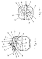
- Fig. 1
- eine perspektivische Ansicht einer Vorrichtung nach der Erfindung mit zueinander ausgerichteten Rahmen,
- Fig. 2
- eine Seitenansicht der Vorrichtung nach Fig. 1 mit zueinander verschwenkten Rahmen,
- Fig. 3
- eine Draufsicht aufdie Vorrichtung entsprechend Fig. 2,
- Fig. 4
- eine Draufsicht auf die Vorrichtung nach Fig. 1 mit einem an einem Mittelgriff gesicherten Faß bei zueinander ausgerichteten Rahmen,
- Fig. 5
- eine Frontansicht der Vorrichtung nach Fig. 1 mit einem an zwei Seitengriffen sicherten Faß,
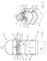
- Fig. 6
- perspektivisch eine verkleinerte Vorrichtung mit einer mittleren Halteeinrichtung zur Sicherung eines Kanisters mit oberem Mittelgriff,
- Fig. 7
- eine perspektivische Ansicht einer drei gleiche Halteeinrichtungen aufweisenden Vorrichtung mit einem an zwei Seitengriffen gesicherten Faß,
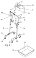
- Fig. 8
- perspektivisch einen Transportwagen mit Winde für eine Vorrichtung nach der Erfindung und darüber in Teildarstellung einen Transportwagen ohne Winde,
- Fig. 9
- den Transportwagen wie in Fig. 8 mit einer auf dem höhenverstellbaren Schlitten eingehängten Faßentleerungsvorrichtung,
- Fig. 10
- in ähnlicher Darstellung wie in Fig. 9 eine in den Hubschlitten eingehängte Faßentleerungsvorrichtung in oberer Endstellung, und
- Fig. 11
- die Vorrichtung wie in Fig. 10 im Gebrauch bei mit dem Faß verschwenkten Kipprahmen.
Claims (20)
- Vorrichtung zum dosierten Ausgießen vom Flüssigkeit aus einem Faß (70; 84), das wenigstens einen von oben zugänglichen Griff (72; 82) aufweist, mit einem Tragrahmen (10), der gemeinsam mit einem daran um eine horizontale Kippachse (18) drehgelagerten Kipprahmen (20) in eine das stehende Faß (70; 84) übergreifende und seitlich zumindest teilweise umfassende Beziehung bringbar ist, wobei der Kipprahmen (20) das Faß (70; 84) seitlich abstützende Mittel (22, 24) und wenigstens eine obere Halteeinrichtung (30; 32) aufweist, dadurch gekennzeichnet, daß die Halteeinrichtung (30; 32) aus wenigstens einem, dem Faßgriff zugeordneten und diesen untergreifend verstellbaren Greifhaken (46; 76) besteht.
- Vorrichtung nach Anspruch 1, dadurch gekennzeichnet, daß die Halteeinrichtung (32) mindestens einen parallel oberhalb des zugeordneten Faßgriffes am Kipprahmen (20) drehbar gelagerten horizontalen Bolzen (74) aufweist, an dem der wenigstens eine Greifhaken (76) so befestigt ist, daß er mit seiner Öffnung in einer zum Bolzen (74) senkrechten Ebene zwischen einer Freigabe-Position und einer den Faßgriff (82) untergreifenden Eingriff-Position verschwenkbar ist.
- Vorrichtung nach Anspruch 2, dadurch gekennzeichnet, daß an einem oberen Querträger (28) des Kipprahmens (20) sowohl das Drehlager (75) des Bolzens (74) als auch ein sich in den Schwenkweg des Greifhakens (76) erstreckender Anschlag (80) als Ruhe-Auflage für den in die Freigabe-Position verschwenkten Greifhaken befestigt ist.
- Vorrichtung nach Anspruch 2 oder 3, dadurch gekennzeichnet, daß an dem bezüglich seines Drehlagers (75) aufgrund von Axialspiel längsverschiebbaren Bolzen (74) seitlich ein paralleler Haltestift (86) befestigt ist, der in der Eingriff-Position des Greifhakens durch Längsverschiebung als mit dem Querträger (28) in Eingriff kommende Rückdreh-Sicherung aktivierbar ist.
- Vorrichtung nach Anspruch 4, dadurch gekennzeichnet, daß am Drehlager (75) ein Sicherheitsanschlag (87) an einer Stelle im Schwenkweg des durch unbeabsichtigte Längsverschiebung aktivierten Haltestiftes (86) angeordnet ist, an welcher der Greifhaken (76) sich nahe seiner Freigabe-Position befindet.
- Vorrichtung nach einem der Ansprüche 2 bis 5, dadurch gekennzeichnet, daß der Bolzen (74) beiderseits seines Drehlagers (75) bzw. des Querträgers (28) je einen Greifhaken (76) trägt und einenends mit einem Drehgriff (78) versehen ist.
- Vorrichtung nach einem der Ansprüche 2 bis 6, dadurch gekennzeichnet, daß eine auf dem Querträger (28) mittig angeordnete Halteeinrichtung (32) zur Sicherung von Fässern mit Mittelgriff wahlweise durch zwei nahe den Querträgerenden angeordnete Halteeinrichtungen derselben Art wie die mittlere Halteeinrichtung zur Sicherung von Fässern mit zwei Seitengriffen ergänzt oder ersetzt ist.
- Vorrichtung nach Anspruch 1, dadurch gekennzeichnet, daß die Halteeinrichtung (30) mindestens einen oberhalb des zugeordneten Faßgriffes an einem oberen Querträger (28) des Kipprahmens (20) gelagerten vertikalen Bolzen (44) aufweist, der am unteren Ende als Greifhaken (46) ausgebildet und zwischen einer Freigabe- und einer Eingriff-Position zum Untergreifen des Faßgriffes drehbar ist.
- Vorrichtung nach Anspruch 8, dadurch gekennzeichnet, daß die Halteeinrichtung (30) zur Sicherung von Fässern mit zwei oberen Seitengriffen zwei im Bereich der Querträgerenden gelagerte, durch Greifhaken verlängerte vertikale Bolzen (44) aufweist, an die zur gemeinsamen Drehverstellung ein federbelastetes Hebelsystem (50) angeschlossen ist, das mittels eines Handhebels (52) zwischen die Freigabe- und Eingriff-Positionen der Greifhaken (46) definierenden Anschlägen (62, 68) betätigbar ist.
- Vorrichtung gekennzeichnet durch eine Kombination der Merkmale der Ansprüche 2 und 9.
- Vorrichtung nach Anspruch 10, dadurch gekennzeichnet, daß das Hebelsystem (50) oberhalb des horizontalen Bolzens (74) der mittigen Halteeinrichtung (32) so am Kipprahmen (20) angeordnet ist, daß es in seiner der Eingriff-Position der Greifhaken (46) entsprechenden Endstellung eine Betätigung der mittigen Halteeinrichtung (32) blockiert.
- Vorrichtung nach einem der vorhergehenden Ansprüche, dadurch ge-kennzeichnet, daß der Tragrahmen (10) zwei durch einen oberen Bügel (17) verbundene senkrechte Schenkel (14) aufweist, zwischen denen der aus zwei durch den oberen Querträger (28) verbundenen Schenkeln (21) bestehende Kipprahmen (20) um die durch jeweils benachbarte Rahmenschenkel verbindende Gelenkbolzen gebildete Kippachse (18) schwenkbar ist, und daß beide Rahmen bei zueinander ausgerichteten Schenkeln mittels eines verstellbaren Fallenriegels (40) gesichert sind.
- Vorrichtung nach einem der vorhergehenden Ansprüche, dadurch gekennzeichnet, daß die Kippachse (18) nahe oberhalb des gemeinsamen Schwerpunktes von Kipprahmen (20) und darin gesichertem Faß angeordnet ist.
- Vorrichtung nach einem der vorhergehenden Ansprüche, dadurch gekennzeichnet, daß der Kipprahmen seitlich oben einen Handgriff (38) und nahe seinem unteren Ende Anschlagmittel (42) trägt, die zur Begrenzung der Kippbewegung mit dem Tragrahmen (10) zusammenwirken.
- Vorrichtung nach einem der vorhergehenden Ansprüche, dadurch gekennzeichnet, daß sich der Kipprahmen (20), ausgehend vom Querträger (28), etwa über 2/3 der Faßhöhe erstreckt und die das Faß seitlich abstützenden Mittel aus wenigstens zwei im unteren und mittleren Bereich der senkrechten Kipprahmenschenkel (21) unter vertikalem Abstand befestigten, waagerechten Bügeln (22, 24) bestehen, die dem halben Faßumfang angepaßt sind.
- Vorrichtung nach einem der vorhergehenden Ansprüche, dadurch gekennzeichnet, daß eine am Querträger (28) verstellbare Belüftungseinrichtung (88) ein winklig abgebogenes Rohr (92) sowie eine lösbare Halterung (90) für den aus der Faßöffnung (96) herausragenden Rohrschenkel (98) aufweist, wobei der andere Rohrschenkel (94) im Innern des Fasses entlang dessen Oberseite verläuft.
- Vorrichtung nach einem der vorhergehenden Ansprüche, dadurch gekennzeichnet, daß der Bügel (17) des in seinem oberen Bereich querversteiften Tragrahmens (10) unmittelbar oder mittels einer daran befestigten Kranöse (12) zum Aufhängen an einem Transportwagen (110) oder Hebezeug ausgebildet ist.
- Transportwagen mit einer Faßentleerungs-Vorrichtung nach Anspruch 17, gekennzeichnet durch einen auf Rollen (114) fahrbaren, etwa rechteckigen und an einer Seite offenen Grundrahmen (112), auf dessen mit größerem Abstand als die Breite des aufzuhängenden Tragrahmens (10) gegenüberliegenden Rahmenseiten zwei aufrechte oder leicht geneigte Schenkel (126) eines Haltegestells (124) befestigt sind,
und durch einen die Schenkel (126) verbindenden und mit in solcher Höhe angeordneten Haltemitteln versehenen Quersteg (130), daß der daran angehängte Tragrahmen (10) einschließlich des im Kipprahmen gesicherten Fasses sich über der Höhe einer Auffangwanne (120) befinden. - Transportwagen nach Anspruch 18, dadurch gekennzeichnet, daß der Abstand zwischen den Rahmenseiten des Grundrahmens (112) größer ist als die Breite einer Auffangwanne (120), jedoch die waagerechte Oberseite von auf den Rahmenseiten befestigten, gegeneinander geneigten Leisten (116) einen verringerten Abstand zur Abstützung oberer Ränder (122) einer auf dem Transportwagen unter dem aufgehängten Faß mitzuführenden Auffangwanne aufweisen.
- Transportwagen nach Anspruch 18 oder 19, dadurch gekennzeichnet, daß die Haltemittel aus einer nach oben offenen Aufnahme (132) für den Bügel (17) oder die Öse (12) des Tragrahmens (10) bestehen, die am Quersteg (130) oder an einem an den Schenkeln (126) des Haltegestells (124) geführten Schlitten (144) befestigt ist, der mittels einer am Quersteg (130) in einem Windengestell (138) gelagerten Winde höhenverstellbar ist.
Applications Claiming Priority (2)
| Application Number | Priority Date | Filing Date | Title |
|---|---|---|---|
| DE19548203A DE19548203C1 (de) | 1995-12-22 | 1995-12-22 | Vorrichtung zum Ausgießen von Flüssigkeit aus einem Faß |
| DE19548203 | 1995-12-22 |
Publications (2)
| Publication Number | Publication Date |
|---|---|
| EP0780330A1 EP0780330A1 (de) | 1997-06-25 |
| EP0780330B1 true EP0780330B1 (de) | 2000-03-15 |
Family
ID=7781055
Family Applications (1)
| Application Number | Title | Priority Date | Filing Date |
|---|---|---|---|
| EP96119576A Expired - Lifetime EP0780330B1 (de) | 1995-12-22 | 1996-12-06 | Vorrichtung zum Ausgiessen von Flüssigkeit aus einem Fass |
Country Status (2)
| Country | Link |
|---|---|
| EP (1) | EP0780330B1 (de) |
| DE (2) | DE19548203C1 (de) |
Families Citing this family (4)
| Publication number | Priority date | Publication date | Assignee | Title |
|---|---|---|---|---|
| DE29907967U1 (de) * | 1999-05-05 | 1999-08-12 | Protechna Sa | Vorrichtung zum Entleeren von Transport- und Lagerbehältern für Flüssigkeiten |
| CN107127202A (zh) * | 2017-05-09 | 2017-09-05 | 厦门好绿盛生态农业有限公司 | 豆芽桶洗桶自动化装置 |
| CN107804817A (zh) * | 2017-11-27 | 2018-03-16 | 昆山市华新电路板有限公司 | 利于油墨桶倒净的辅助治具 |
| CN108622672B (zh) * | 2018-07-20 | 2024-01-05 | 伊川县东风磨料磨具有限公司 | 一种熔融合成刚玉凝固包自动翻转装置 |
Family Cites Families (8)
| Publication number | Priority date | Publication date | Assignee | Title |
|---|---|---|---|---|
| FR439700A (fr) * | 1912-02-03 | 1912-06-20 | Boissons Hygieniques Soc D | Monte-pots à lait |
| US2605071A (en) * | 1948-01-12 | 1952-07-29 | Alfred H C Trepte | Collapsible dispensing rack |
| US2937836A (en) * | 1958-02-07 | 1960-05-24 | Martin M Fleischman | Apparatus for handling barrels |
| US4688838A (en) * | 1986-03-03 | 1987-08-25 | Burlington Industries, Inc. | Twister bobbin lifter and carrier |
| DE8712645U1 (de) * | 1987-09-18 | 1987-12-10 | Fuchs, Heinrich, 89558 Böhmenkirch | Haltevorrichtung für Flüssigkeitsbehälter |
| DE4100742A1 (de) * | 1991-01-12 | 1992-07-16 | Henkel Kgaa | Ausgiesshilfe fuer kanister in form eines belueftungsrohres |
| US5406996A (en) * | 1994-02-17 | 1995-04-18 | Wagner; Larry L. | Bottled water lifting apparatus |
| US5425614A (en) * | 1994-11-16 | 1995-06-20 | Perussi; Rolando | Bottle lifting and inverting apparatus |
-
1995
- 1995-12-22 DE DE19548203A patent/DE19548203C1/de not_active Expired - Fee Related
-
1996
- 1996-12-06 DE DE59604671T patent/DE59604671D1/de not_active Expired - Fee Related
- 1996-12-06 EP EP96119576A patent/EP0780330B1/de not_active Expired - Lifetime
Also Published As
| Publication number | Publication date |
|---|---|
| DE59604671D1 (de) | 2000-04-20 |
| DE19548203C1 (de) | 1997-02-20 |
| EP0780330A1 (de) | 1997-06-25 |
Similar Documents
| Publication | Publication Date | Title |
|---|---|---|
| US5487446A (en) | Apparatus for self-adjusting the height of an outrigger attachable to scaffolding | |
| DE10123991C2 (de) | Handbetriebener Hubstapler | |
| EP1979216B1 (de) | Transport- und hebevorrichtung für gasflaschen | |
| EP0780330A1 (de) | Vorrichtung zum Ausgiessen von Flüssigkeit aus einem Fass | |
| EP0204686A1 (de) | Sammeleinrichtung insbesondere für Altmaterial, wie Altglas od.dgl. | |
| DE29903671U1 (de) | Regalfahrzeug | |
| DE2909532A1 (de) | Kippbehaelter fuer hublader | |
| DE2733520A1 (de) | Wagen zur handhabung von lasten | |
| CH665200A5 (de) | Kettbaumwagen. | |
| DE102010034864B4 (de) | Aufnahmevorrichtung | |
| DE202004007018U1 (de) | Transportwagen für eimerförmige Gebinde | |
| LU102978B1 (de) | Trolley für Taschen und Tüten mit Hand Tragegriff | |
| DE4134948C2 (de) | Transportwagen, insbesondere für Leerkettbäume | |
| DE29618730U1 (de) | Wechselbehälter | |
| DE69016769T2 (de) | Anhänger und geeigneter Behälter. | |
| DE29720062U1 (de) | Vorrichtung zum Kippen eines Fasses | |
| DE3234295C1 (de) | Vorrichtung zum Bereiten von Chargen von Estrich, Vergußmassen oder dergleichen und Verbringen derselben zum Einsatzort | |
| DE2733520C2 (de) | Wagen zum Transport von Lasten | |
| DE29721911U1 (de) | Handwagen, faltbar | |
| AT363333B (de) | Fassabfuellbock mit wanne | |
| DE2604049C3 (de) | Vorrichtung zum Ankuppeln von Großraum-Müllsammelbehältern an Hubroller | |
| DE1728118A1 (de) | Reinigungskarren | |
| DE1066142B (de) | ||
| DE2230665C3 (de) | Kippvorrichtung | |
| EP3251919A1 (de) | Transportvorrichtung für tauchsportausrüstung |
Legal Events
| Date | Code | Title | Description |
|---|---|---|---|
| PUAI | Public reference made under article 153(3) epc to a published international application that has entered the european phase |
Free format text: ORIGINAL CODE: 0009012 |
|
| AK | Designated contracting states |
Kind code of ref document: A1 Designated state(s): DE FR IT NL |
|
| 17P | Request for examination filed |
Effective date: 19970513 |
|
| 17Q | First examination report despatched |
Effective date: 19980701 |
|
| GRAG | Despatch of communication of intention to grant |
Free format text: ORIGINAL CODE: EPIDOS AGRA |
|
| GRAG | Despatch of communication of intention to grant |
Free format text: ORIGINAL CODE: EPIDOS AGRA |
|
| GRAH | Despatch of communication of intention to grant a patent |
Free format text: ORIGINAL CODE: EPIDOS IGRA |
|
| GRAH | Despatch of communication of intention to grant a patent |
Free format text: ORIGINAL CODE: EPIDOS IGRA |
|
| GRAA | (expected) grant |
Free format text: ORIGINAL CODE: 0009210 |
|
| AK | Designated contracting states |
Kind code of ref document: B1 Designated state(s): DE FR IT NL |
|
| REF | Corresponds to: |
Ref document number: 59604671 Country of ref document: DE Date of ref document: 20000420 |
|
| ITF | It: translation for a ep patent filed | ||
| ET | Fr: translation filed | ||
| PLBE | No opposition filed within time limit |
Free format text: ORIGINAL CODE: 0009261 |
|
| STAA | Information on the status of an ep patent application or granted ep patent |
Free format text: STATUS: NO OPPOSITION FILED WITHIN TIME LIMIT |
|
| 26N | No opposition filed | ||
| PGFP | Annual fee paid to national office [announced via postgrant information from national office to epo] |
Ref country code: FR Payment date: 20011114 Year of fee payment: 6 |
|
| PGFP | Annual fee paid to national office [announced via postgrant information from national office to epo] |
Ref country code: NL Payment date: 20011220 Year of fee payment: 6 |
|
| PGFP | Annual fee paid to national office [announced via postgrant information from national office to epo] |
Ref country code: DE Payment date: 20030225 Year of fee payment: 7 |
|
| PG25 | Lapsed in a contracting state [announced via postgrant information from national office to epo] |
Ref country code: NL Free format text: LAPSE BECAUSE OF NON-PAYMENT OF DUE FEES Effective date: 20030701 |
|
| NLV4 | Nl: lapsed or anulled due to non-payment of the annual fee |
Effective date: 20030701 |
|
| PG25 | Lapsed in a contracting state [announced via postgrant information from national office to epo] |
Ref country code: FR Free format text: LAPSE BECAUSE OF NON-PAYMENT OF DUE FEES Effective date: 20030901 |
|
| REG | Reference to a national code |
Ref country code: FR Ref legal event code: ST |
|
| PG25 | Lapsed in a contracting state [announced via postgrant information from national office to epo] |
Ref country code: DE Free format text: LAPSE BECAUSE OF NON-PAYMENT OF DUE FEES Effective date: 20040701 |
|
| PG25 | Lapsed in a contracting state [announced via postgrant information from national office to epo] |
Ref country code: IT Free format text: LAPSE BECAUSE OF NON-PAYMENT OF DUE FEES;WARNING: LAPSES OF ITALIAN PATENTS WITH EFFECTIVE DATE BEFORE 2007 MAY HAVE OCCURRED AT ANY TIME BEFORE 2007. THE CORRECT EFFECTIVE DATE MAY BE DIFFERENT FROM THE ONE RECORDED. Effective date: 20051206 |