EP0780337A2 - Passenger conveyor control system having decentralized inputs and outputs - Google Patents
Passenger conveyor control system having decentralized inputs and outputs Download PDFInfo
- Publication number
- EP0780337A2 EP0780337A2 EP96120445A EP96120445A EP0780337A2 EP 0780337 A2 EP0780337 A2 EP 0780337A2 EP 96120445 A EP96120445 A EP 96120445A EP 96120445 A EP96120445 A EP 96120445A EP 0780337 A2 EP0780337 A2 EP 0780337A2
- Authority
- EP
- European Patent Office
- Prior art keywords
- control unit
- control system
- passenger conveyor
- truss
- passenger
- Prior art date
- Legal status (The legal status is an assumption and is not a legal conclusion. Google has not performed a legal analysis and makes no representation as to the accuracy of the status listed.)
- Granted
Links
- 238000004891 communication Methods 0.000 claims description 9
- 238000012423 maintenance Methods 0.000 description 6
- 238000012986 modification Methods 0.000 description 5
- 230000004048 modification Effects 0.000 description 5
- 230000008901 benefit Effects 0.000 description 4
- 238000009434 installation Methods 0.000 description 4
- 230000008859 change Effects 0.000 description 3
- 230000008439 repair process Effects 0.000 description 3
- 238000007792 addition Methods 0.000 description 2
- 238000012544 monitoring process Methods 0.000 description 2
- 238000012546 transfer Methods 0.000 description 2
- 230000005540 biological transmission Effects 0.000 description 1
- 125000004122 cyclic group Chemical group 0.000 description 1
- 230000001419 dependent effect Effects 0.000 description 1
- 238000000034 method Methods 0.000 description 1
- 230000008569 process Effects 0.000 description 1
- 230000000135 prohibitive effect Effects 0.000 description 1
- 230000008054 signal transmission Effects 0.000 description 1
Images

Classifications
-
- B—PERFORMING OPERATIONS; TRANSPORTING
- B66—HOISTING; LIFTING; HAULING
- B66B—ELEVATORS; ESCALATORS OR MOVING WALKWAYS
- B66B25/00—Control of escalators or moving walkways
Definitions
- the present invention relates to passenger conveyors, and more particularly to control systems for such passenger conveyors.
- a typical passenger conveyor such as an escalator or moving walk, includes a truss, a plurality of sequentially connected treadplates traveling through a closed loop path within the truss, and a machine for driving the treadplates.
- the machine is located in a space under the one of the landings.
- Modem escalators and moving walks include devices such as sensors for monitoring speed, sensors for detecting missing treadplates, devices for monitoring wear; actuators for utilizing special purpose devices, such as steps to accommodate wheelchairs; and output devices, such as traffic lights.
- Each of these devices includes a combination of interface devices, i.e., sensors or actuators, that are connected to a central control unit.
- the size of the control unit presents problems because it is located in the machine space and typically must be removed in order to service the passenger conveyor.
- the complexity of the control unit presents further problems because as more interface devices become available, it is desirable to back-fit them onto existing passenger conveyors. Modifying existing passenger conveyors to take advantage of new interface devices requires a new control unit to replace the old one and additional wiring connections to be made between the interface device and the control unit. The cost associated with such modifications may become prohibitive.
- a control system for a passenger conveyor includes a plurality of junction boxes, each having one or more input/output (I/O) modules, and a control unit.
- the I/O modules communicate with the various types of interface devices, e.g., sensors, actuators, etc.
- the plurality of I/O modules communicate with the control unit via a serial link connected to a bus master within the control unit.
- each interface unit has its own I/O module, new interface devices may be added, or obsolete interface devices may be removed, without having to replace the control unit.
- the cost associated with installing and with modifying the control system of the passenger conveyor is minimized as a result of using a serial link to provide communication between the control unit and the interface devices. Having a single, serial link requires less installation time and less material cost than the previous configurations that require each interface device to be individually wired into the control unit. Modifications of the control system can be accomplished more expeditiously and cost effectively. Any additional interface devices require only a simple connection into the serial link rather than installation of additional wiring through the limited workspace within the truss. As a further advantage, the size of the control unit is minimized because of the distribution of the I/O modules throughout the passenger conveyor.
- control unit including bus master is located remotely from the truss of the passenger conveyor. This feature removes the control unit from the machine space under the landing, thereby increasing the available space within the machine space in which to perform maintenance. In prior configurations, the control unit because of its size and location would have to be removed in order to conduct maintenance and repairs within the machine space. Handling the control unit during maintenance and repair increased the cost associated with conducting the maintenance and repair and also increased the likelihood of damage occurring to the control unit during the conduct of such services.
- Fig. 1 is a perspective view, partially cut away, of an escalator.
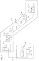
- Fig. 2 is a schematic view illustrating a control system for the escalator.
- Fig. 1 shows an escalator 10 as an exemplary embodiment of a passenger conveyor and is used to describe the present invention. It should become apparent in the ensuing description that the invention is applicable to other passenger conveyors, such as moving walks.
- the escalator 10 includes a truss 12 extending between a lower landing 14 and an upper landing 16, a plurality of sequentially connected treadplates 18 connected to a step chain 20 and traveling through a closed loop path within the truss 12, a pair of balustrades 22 having handrails 24, and a machine 26 for driving the treadplates 18 and handrails 24.
- the machine 26 is located in a machine space 28 under the upper landing 16.
- the escalator 10 includes a plurality of operational devices 32 distributed throughout the truss 12.
- the devices 32 are the following sensors: a speed sensor 34 for the treadplates 18, a sensor 36 to detect missing treadplates 18, a limit switch 38 to detect excessive wear of the step chain 20 and treadplates 18, and a sensor 42 to monitor the speed of the handrails 24.
- the devices 32 are the following actuators: a pair of switches 44 one in each landing 14,16, to detect the presence of a passenger and to trigger a change in speed of the escalator 10, and a pair of switches 46, also in each landing 14,16, to actuate the operation of a wheelchair platform embedded into the treadplates 18.
- output devices such as a traffic light 47 indicating direction of travel.
- a control system 48 is in communication with each of these operational devices 32 and includes a control unit 52, a bus master 54, a serial link 56, a plurality of junction boxes 58 and a machine communication link 62.
- the control system 48 is represented schematically in Fig. 2.
- junction boxes 58 are disposed proximate to the operational device 32 to which it is connected.
- the junction boxes 58 are located in the upper and lower landings 14,16.
- the junction boxes 58 are distributed throughout the truss 12, dependent upon the location of the applicable sensor. All of the junction boxes 58 are interconnected for communication with the control unit 52.
- Each junction box 58 includes an input/output (I/O) module which is a conventional printed circuit board.
- the I/O module translates the signals from the sensors 34,36,38 into signals that can be communicated to the control unit 52, and conversely translates signals from the control unit 52 into signals that can be communicated to the actuators 44,46 and to the machine 26.
- the junction boxes 58 may also include additional functionality such that the junction box and applicable sensor/actuator may define a subsystem within the control system 48.
- the serial link 56 is a simple conduit for serial transmission of signals from the junction boxes 58 to the control unit 52.
- the serial link 56 cyclically transfers the signals from each of the junction boxes 58 to the bus master 54 of the control unit 52.
- the bus master 54 accepts the transmissions over the serial link 56 and processes them directly to the control unit 52.
- the bus master and cyclic transfer of signals may be replaced by a system whereupon signals are transmitted only upon a change in condition.
- the control unit 52 incorporates the control logic for operation of the escalator 10. Signals representing the operational condition of the escalator 10 are continuously received from the bus master 54 and monitored by the control unit 52. If a signal received indicates that there is a change in operational condition, the control unit 52 can communicate through its own I/O module 64 to the appropriate device of the escalator. For example, if the direction of travel is in the up direction, an appropriate signal will be output to the traffic light. On the other hand, if the escalator 10 is operating in an idle mode and the switch 38 detects the presence of a passenger, the control unit 52 can actuate the machine 26 to accelerate to an operational speed.
- control unit 52 is located remotely from the truss 12. This location is facilitated by the flexibility of the control system 48 and provides the benefit of removing the control unit 52 from within the upper landing 16. Removing the control unit 52 increases the space available for other escalator 10 components and for the conduct of necessary maintenance. In addition, unnecessary handling of the control unit 52 is no longer required in order to perform such maintenance within the landing 16.
Landscapes
- Escalators And Moving Walkways (AREA)
Abstract
Description
- The present invention relates to passenger conveyors, and more particularly to control systems for such passenger conveyors.
- A typical passenger conveyor, such as an escalator or moving walk, includes a truss, a plurality of sequentially connected treadplates traveling through a closed loop path within the truss, and a machine for driving the treadplates. The machine is located in a space under the one of the landings.
- Control systems for such conveyors have become increasingly complex. Modem escalators and moving walks include devices such as sensors for monitoring speed, sensors for detecting missing treadplates, devices for monitoring wear; actuators for utilizing special purpose devices, such as steps to accommodate wheelchairs; and output devices, such as traffic lights. Each of these devices includes a combination of interface devices, i.e., sensors or actuators, that are connected to a central control unit.
- As the number of interface devices has increased, the size and complexity of the control unit has increased. The size of the control unit presents problems because it is located in the machine space and typically must be removed in order to service the passenger conveyor. The complexity of the control unit presents further problems because as more interface devices become available, it is desirable to back-fit them onto existing passenger conveyors. Modifying existing passenger conveyors to take advantage of new interface devices requires a new control unit to replace the old one and additional wiring connections to be made between the interface device and the control unit. The cost associated with such modifications may become prohibitive.
- The above art notwithstanding, scientists and engineers under the direction of Applicant's Assignee are working to develop control systems for passenger conveyors that are both flexible and cost effective.
- According to the present invention, a control system for a passenger conveyor includes a plurality of junction boxes, each having one or more input/output (I/O) modules, and a control unit. The I/O modules communicate with the various types of interface devices, e.g., sensors, actuators, etc. The plurality of I/O modules communicate with the control unit via a serial link connected to a bus master within the control unit.
- Decentralizing the I/O modules results in maximizing the flexibility of the control system. Since each interface unit has its own I/O module, new interface devices may be added, or obsolete interface devices may be removed, without having to replace the control unit. In addition, the cost associated with installing and with modifying the control system of the passenger conveyor is minimized as a result of using a serial link to provide communication between the control unit and the interface devices. Having a single, serial link requires less installation time and less material cost than the previous configurations that require each interface device to be individually wired into the control unit. Modifications of the control system can be accomplished more expeditiously and cost effectively. Any additional interface devices require only a simple connection into the serial link rather than installation of additional wiring through the limited workspace within the truss. As a further advantage, the size of the control unit is minimized because of the distribution of the I/O modules throughout the passenger conveyor.
- In a particular embodiment of the present invention, the control unit including bus master is located remotely from the truss of the passenger conveyor. This feature removes the control unit from the machine space under the landing, thereby increasing the available space within the machine space in which to perform maintenance. In prior configurations, the control unit because of its size and location would have to be removed in order to conduct maintenance and repairs within the machine space. Handling the control unit during maintenance and repair increased the cost associated with conducting the maintenance and repair and also increased the likelihood of damage occurring to the control unit during the conduct of such services.
- The foregoing and other objects, features and advantages of the present invention become more apparent in light of the following detailed description of the exemplary embodiments thereof, as illustrated in the accompanying drawings.
- Fig. 1 is a perspective view, partially cut away, of an escalator.
- Fig. 2 is a schematic view illustrating a control system for the escalator.
- Fig. 1 shows an
escalator 10 as an exemplary embodiment of a passenger conveyor and is used to describe the present invention. It should become apparent in the ensuing description that the invention is applicable to other passenger conveyors, such as moving walks. Theescalator 10 includes a truss 12 extending between alower landing 14 and anupper landing 16, a plurality of sequentially connectedtreadplates 18 connected to astep chain 20 and traveling through a closed loop path within the truss 12, a pair ofbalustrades 22 havinghandrails 24, and amachine 26 for driving thetreadplates 18 andhandrails 24. Themachine 26 is located in amachine space 28 under theupper landing 16. - The
escalator 10 includes a plurality ofoperational devices 32 distributed throughout the truss 12. Among thedevices 32 are the following sensors: aspeed sensor 34 for thetreadplates 18, asensor 36 to detectmissing treadplates 18, alimit switch 38 to detect excessive wear of thestep chain 20 andtreadplates 18, and asensor 42 to monitor the speed of thehandrails 24. Also among thedevices 32 are the following actuators: a pair ofswitches 44 one in eachlanding escalator 10, and a pair ofswitches 46, also in eachlanding treadplates 18. In addition, there are output devices, such as atraffic light 47 indicating direction of travel. - A
control system 48 is in communication with each of theseoperational devices 32 and includes acontrol unit 52, abus master 54, aserial link 56, a plurality ofjunction boxes 58 and amachine communication link 62. Thecontrol system 48 is represented schematically in Fig. 2. - Each of the
junction boxes 58 is disposed proximate to theoperational device 32 to which it is connected. For theswitches traffic light 47, thejunction boxes 58 are located in the upper andlower landings sensors junction boxes 58 are distributed throughout the truss 12, dependent upon the location of the applicable sensor. All of thejunction boxes 58 are interconnected for communication with thecontrol unit 52. Eachjunction box 58 includes an input/output (I/O) module which is a conventional printed circuit board. The I/O module translates the signals from thesensors control unit 52, and conversely translates signals from thecontrol unit 52 into signals that can be communicated to theactuators machine 26. Although described asjunction boxes 58, it should be noted that thejunction boxes 58 may also include additional functionality such that the junction box and applicable sensor/actuator may define a subsystem within thecontrol system 48. - The
serial link 56 is a simple conduit for serial transmission of signals from thejunction boxes 58 to thecontrol unit 52. Theserial link 56 cyclically transfers the signals from each of thejunction boxes 58 to thebus master 54 of thecontrol unit 52. Thebus master 54 accepts the transmissions over theserial link 56 and processes them directly to thecontrol unit 52. As an alternative embodiment, the bus master and cyclic transfer of signals may be replaced by a system whereupon signals are transmitted only upon a change in condition. - The
control unit 52 incorporates the control logic for operation of theescalator 10. Signals representing the operational condition of theescalator 10 are continuously received from thebus master 54 and monitored by thecontrol unit 52. If a signal received indicates that there is a change in operational condition, thecontrol unit 52 can communicate through its own I/O module 64 to the appropriate device of the escalator. For example, if the direction of travel is in the up direction, an appropriate signal will be output to the traffic light. On the other hand, if theescalator 10 is operating in an idle mode and theswitch 38 detects the presence of a passenger, thecontrol unit 52 can actuate themachine 26 to accelerate to an operational speed. - As shown in Fig. 1, the
control unit 52 is located remotely from the truss 12. This location is facilitated by the flexibility of thecontrol system 48 and provides the benefit of removing thecontrol unit 52 from within theupper landing 16. Removing thecontrol unit 52 increases the space available forother escalator 10 components and for the conduct of necessary maintenance. In addition, unnecessary handling of thecontrol unit 52 is no longer required in order to perform such maintenance within thelanding 16. - Installation of the
escalator 10 is less labor intensive and time consuming since there is no longer a need to directly wire each sensor and actuator into thecontrol unit 52. Upgrades and modifications of thecontrol system 48 are also facilitated by the invention. The addition of new sensors and actuators requires only the installation of the sensor or actuator and a junction box. Since theserial link 56 is already present, a modification only requires connection of the new junction box into theserial link 56 and corresponding changes in thecontrol unit 52 to accommodate the modification. - Although the invention has been shown and described with respect to exemplary embodiments thereof, it should be understood by those skilled in the art that various changes, omissions, and additions may be made thereto, without departing from the spirit and scope of the invention.
Claims (4)
- A control system for a passenger conveyor, the passenger conveyor including a truss, passenger carrying means disposed within the truss, means for driving the passenger carrying means disposed within the truss and engaged with the passenger carrying means, a plurality of operational interface devices, and the control system, wherein the control system includes:a plurality of junction boxes, each junction box having at least one input/output (I/O) module, each I/O module in communication with one or more of the plurality of operational interface devices;a control unit in communication with the driving means of the passenger conveyor, the control unit including a bus master;a link for providing serial communication between the plurality of I/O modules and the control unit.
- The control system according to Claim 1, wherein the control unit is located remotely from the truss.
- The control system according to Claim 1, wherein the passenger conveyor includes a pair of landings disposed on opposite ends of the passenger conveyor, and wherein one of the plurality of junction boxes in located in the first landing of the passenger conveyor and another of the plurality of junction boxes is located in the opposite landing of the passenger conveyor.
- The control system according to Claim 1, further including a subsystem having an I/O module and an operational interface, the operational interface device being in communication with the I/O module of the subsystem, and wherein the subsystem I/O module is in communication with the bus master through the serial link.
Applications Claiming Priority (2)
| Application Number | Priority Date | Filing Date | Title |
|---|---|---|---|
| US574809 | 1995-12-19 | ||
| US08/574,809 US5697485A (en) | 1995-12-19 | 1995-12-19 | Passenger conveyor control system having decentralized inputs and outputs |
Publications (3)
| Publication Number | Publication Date |
|---|---|
| EP0780337A2 true EP0780337A2 (en) | 1997-06-25 |
| EP0780337A3 EP0780337A3 (en) | 1997-07-16 |
| EP0780337B1 EP0780337B1 (en) | 2003-10-15 |
Family
ID=24297742
Family Applications (1)
| Application Number | Title | Priority Date | Filing Date |
|---|---|---|---|
| EP96120445A Revoked EP0780337B1 (en) | 1995-12-19 | 1996-12-18 | Passenger conveyor control system having decentralized inputs and outputs |
Country Status (6)
| Country | Link |
|---|---|
| US (1) | US5697485A (en) |
| EP (1) | EP0780337B1 (en) |
| JP (1) | JPH09202577A (en) |
| CN (1) | CN1076708C (en) |
| AT (1) | ATE252050T1 (en) |
| DE (1) | DE69630357T2 (en) |
Cited By (7)
| Publication number | Priority date | Publication date | Assignee | Title |
|---|---|---|---|---|
| WO1998018712A1 (en) * | 1996-10-30 | 1998-05-07 | Otis Elevator Company | Data collection and analysis system for passenger conveyors |
| US6269911B1 (en) * | 1998-09-17 | 2001-08-07 | Inventio Ag | Elevator installation having a central control in a remote central operation center |
| WO2002014200A1 (en) * | 2000-08-11 | 2002-02-21 | Otis Elevator Company | Electronic safety system for escalators |
| FR2835820A1 (en) * | 2002-02-08 | 2003-08-15 | Thyssen Fahrtreppen Gmbh | MOVING STAIRCASE OR MOVING SIDEWALK |
| DE10206449B4 (en) * | 2001-02-13 | 2006-06-29 | Thyssen Fahrtreppen Gmbh | Escalator or moving walk with a control unit |
| EP1777192A1 (en) * | 2005-10-21 | 2007-04-25 | Inventio Ag | Escalator or moving walkway |
| EP2470464A4 (en) * | 2009-08-25 | 2015-08-26 | Kone Corp | TRANSPORT SYSTEM |
Families Citing this family (5)
| Publication number | Priority date | Publication date | Assignee | Title |
|---|---|---|---|---|
| US6848562B2 (en) * | 2003-05-27 | 2005-02-01 | Barry Jay Viola | Device for removal of controller assembly from escalator pit |
| EP1795481A1 (en) * | 2005-12-07 | 2007-06-13 | Inventio Ag | Installation system and method for elevators |
| JP5788580B1 (en) * | 2014-09-12 | 2015-09-30 | 東芝エレベータ株式会社 | Passenger conveyor equipment |
| CN110891891B (en) | 2017-07-19 | 2021-01-05 | 三菱电机株式会社 | Abnormality detection device for passenger conveyor |
| CN109484962A (en) * | 2019-01-24 | 2019-03-19 | 通力电梯有限公司 | It is a kind of for escalator or the control device and control method of pavement |
Citations (1)
| Publication number | Priority date | Publication date | Assignee | Title |
|---|---|---|---|---|
| EP0197876B1 (en) | 1985-03-26 | 1990-07-11 | Anben | Therapeutical composition for use in dermatology containing imidazolidinyl urea as an active substance |
Family Cites Families (10)
| Publication number | Priority date | Publication date | Assignee | Title |
|---|---|---|---|---|
| US3580376A (en) * | 1969-01-02 | 1971-05-25 | Reliance Electric Co | Escalator system having fault indicator |
| US4540890A (en) * | 1982-05-24 | 1985-09-10 | Galber Automazione E | System for selectively addressing electrical control signals from a control unit to a plurality of remote units |
| ATE35667T1 (en) * | 1985-01-12 | 1988-07-15 | Thyssen Man Aufzuege | INSTALLATION SYSTEM FOR AN ELEVATOR. |
| US5000345A (en) * | 1989-05-18 | 1991-03-19 | Pepsico Inc. | Automated drinkmaker system |
| JPH0729749B2 (en) * | 1989-07-21 | 1995-04-05 | 株式会社日立製作所 | Passenger conveyor control device |
| JPH0361291A (en) * | 1989-07-31 | 1991-03-18 | Mitsubishi Electric Corp | Passenger conveyor control device |
| JPH0747460B2 (en) * | 1990-03-02 | 1995-05-24 | 株式会社日立製作所 | Control device for passenger compare |
| JP2572482B2 (en) * | 1990-10-11 | 1997-01-16 | 株式会社日立製作所 | Remote monitoring device for passenger conveyor |
| FI87290C (en) * | 1991-01-17 | 1992-12-10 | Kone Oy | FOERFARANDE FOER BESTAEMNING AV MEDDELANDEIDENTIFIERARE I ETT FOER HISSAR AVSETT DATANAET |
| US5482153A (en) * | 1994-07-25 | 1996-01-09 | Otis Elevator Company | Operation panel for a passenger conveying device |
-
1995
- 1995-12-19 US US08/574,809 patent/US5697485A/en not_active Expired - Fee Related
-
1996
- 1996-12-17 JP JP8336469A patent/JPH09202577A/en active Pending
- 1996-12-18 AT AT96120445T patent/ATE252050T1/en not_active IP Right Cessation
- 1996-12-18 EP EP96120445A patent/EP0780337B1/en not_active Revoked
- 1996-12-18 DE DE69630357T patent/DE69630357T2/en not_active Revoked
- 1996-12-18 CN CN96116705A patent/CN1076708C/en not_active Expired - Fee Related
Patent Citations (1)
| Publication number | Priority date | Publication date | Assignee | Title |
|---|---|---|---|---|
| EP0197876B1 (en) | 1985-03-26 | 1990-07-11 | Anben | Therapeutical composition for use in dermatology containing imidazolidinyl urea as an active substance |
Cited By (12)
| Publication number | Priority date | Publication date | Assignee | Title |
|---|---|---|---|---|
| WO1998018712A1 (en) * | 1996-10-30 | 1998-05-07 | Otis Elevator Company | Data collection and analysis system for passenger conveyors |
| US6269911B1 (en) * | 1998-09-17 | 2001-08-07 | Inventio Ag | Elevator installation having a central control in a remote central operation center |
| WO2002014200A1 (en) * | 2000-08-11 | 2002-02-21 | Otis Elevator Company | Electronic safety system for escalators |
| CN100457598C (en) * | 2000-08-11 | 2009-02-04 | 奥蒂斯电梯公司 | Electronic safety system of escalator |
| EP1502893A3 (en) * | 2000-08-11 | 2009-07-15 | Otis Elevator Company | Electronic safety system for escalators |
| DE10206449B4 (en) * | 2001-02-13 | 2006-06-29 | Thyssen Fahrtreppen Gmbh | Escalator or moving walk with a control unit |
| FR2835820A1 (en) * | 2002-02-08 | 2003-08-15 | Thyssen Fahrtreppen Gmbh | MOVING STAIRCASE OR MOVING SIDEWALK |
| AT500705A1 (en) * | 2002-02-08 | 2006-03-15 | Thyssen Fahrtreppen Gmbh | TRAILER OR RIDE |
| AT500705B1 (en) * | 2002-02-08 | 2007-07-15 | Thyssen Fahrtreppen Gmbh | TRAILER OR RIDE |
| EP1777192A1 (en) * | 2005-10-21 | 2007-04-25 | Inventio Ag | Escalator or moving walkway |
| RU2410322C2 (en) * | 2005-10-21 | 2011-01-27 | Инвенцио Аг | Device to carry people, in particular, moving stairway or footwalk |
| EP2470464A4 (en) * | 2009-08-25 | 2015-08-26 | Kone Corp | TRANSPORT SYSTEM |
Also Published As
| Publication number | Publication date |
|---|---|
| CN1155505A (en) | 1997-07-30 |
| CN1076708C (en) | 2001-12-26 |
| EP0780337B1 (en) | 2003-10-15 |
| US5697485A (en) | 1997-12-16 |
| JPH09202577A (en) | 1997-08-05 |
| DE69630357D1 (en) | 2003-11-20 |
| DE69630357T2 (en) | 2004-06-24 |
| EP0780337A3 (en) | 1997-07-16 |
| ATE252050T1 (en) | 2003-11-15 |
Similar Documents
| Publication | Publication Date | Title |
|---|---|---|
| US5697485A (en) | Passenger conveyor control system having decentralized inputs and outputs | |
| KR100459835B1 (en) | Data collection and analysis system for passenger conveyors | |
| CN103079981B (en) | Elevator safety system and method | |
| CN101368581B (en) | Modular assembly | |
| EP0631965A1 (en) | Method and apparatus for modernizing the control of an elevator group | |
| EP2470464B1 (en) | Conveying system | |
| CN1780782A (en) | Electronic safety systems for escalators | |
| US7104395B2 (en) | Control and power distribution system for a conveyor | |
| HK1039607B (en) | Method for disconnecting transport systems for persons and a security circuit for transport systems for persons | |
| KR101307684B1 (en) | Passenger transportation system | |
| KR0167196B1 (en) | Signal transmission unit of group control elevator | |
| JPWO2021024368A1 (en) | Passenger conveyor renewal method | |
| CN1330031A (en) | Group manage system for elevator | |
| WO2019224882A1 (en) | Renewal method for passenger conveyor | |
| JPH02190538A (en) | Controller of construction machinery | |
| HK1184772A (en) | Elevator safety system and method | |
| HK1184772B (en) | Elevator safety system and method | |
| JPH08163144A (en) | Lan system | |
| HK1031859B (en) | Safety device for escalators and moving walkways | |
| HK1031859A1 (en) | Safety device for escalators and moving walkways | |
| KR19980037334U (en) | Robot sex wiring device of automobile production line | |
| HK1106211A (en) | Passenger transport system particularly elevator system or escalator | |
| HK1090011B (en) | Electronic safety system for escalators | |
| KR19980073116A (en) | Elevator monitoring device |
Legal Events
| Date | Code | Title | Description |
|---|---|---|---|
| PUAI | Public reference made under article 153(3) epc to a published international application that has entered the european phase |
Free format text: ORIGINAL CODE: 0009012 |
|
| PUAL | Search report despatched |
Free format text: ORIGINAL CODE: 0009013 |
|
| AK | Designated contracting states |
Kind code of ref document: A2 Designated state(s): AT DE FR GB |
|
| AK | Designated contracting states |
Kind code of ref document: A3 Designated state(s): AT DE FR GB |
|
| 17P | Request for examination filed |
Effective date: 19970903 |
|
| TPAD | Observations filed by third parties |
Free format text: ORIGINAL CODE: EPIDOS TIPA |
|
| 17Q | First examination report despatched |
Effective date: 19991214 |
|
| GRAH | Despatch of communication of intention to grant a patent |
Free format text: ORIGINAL CODE: EPIDOS IGRA |
|
| GRAS | Grant fee paid |
Free format text: ORIGINAL CODE: EPIDOSNIGR3 |
|
| GRAA | (expected) grant |
Free format text: ORIGINAL CODE: 0009210 |
|
| AK | Designated contracting states |
Kind code of ref document: B1 Designated state(s): AT DE FR GB |
|
| REG | Reference to a national code |
Ref country code: GB Ref legal event code: FG4D |
|
| PGFP | Annual fee paid to national office [announced via postgrant information from national office to epo] |
Ref country code: AT Payment date: 20031104 Year of fee payment: 8 |
|
| REF | Corresponds to: |
Ref document number: 69630357 Country of ref document: DE Date of ref document: 20031120 Kind code of ref document: P |
|
| ET | Fr: translation filed | ||
| PLBQ | Unpublished change to opponent data |
Free format text: ORIGINAL CODE: EPIDOS OPPO |
|
| PLBI | Opposition filed |
Free format text: ORIGINAL CODE: 0009260 |
|
| PLAX | Notice of opposition and request to file observation + time limit sent |
Free format text: ORIGINAL CODE: EPIDOSNOBS2 |
|
| 26 | Opposition filed |
Opponent name: THYSSENKRUPP FAHRTREPPEN GMBH Effective date: 20040714 |
|
| PG25 | Lapsed in a contracting state [announced via postgrant information from national office to epo] |
Ref country code: AT Free format text: LAPSE BECAUSE OF NON-PAYMENT OF DUE FEES Effective date: 20041218 |
|
| PLBB | Reply of patent proprietor to notice(s) of opposition received |
Free format text: ORIGINAL CODE: EPIDOSNOBS3 |
|
| PLCK | Communication despatched that opposition was rejected |
Free format text: ORIGINAL CODE: EPIDOSNREJ1 |
|
| APBM | Appeal reference recorded |
Free format text: ORIGINAL CODE: EPIDOSNREFNO |
|
| APBP | Date of receipt of notice of appeal recorded |
Free format text: ORIGINAL CODE: EPIDOSNNOA2O |
|
| APAH | Appeal reference modified |
Free format text: ORIGINAL CODE: EPIDOSCREFNO |
|
| APBQ | Date of receipt of statement of grounds of appeal recorded |
Free format text: ORIGINAL CODE: EPIDOSNNOA3O |
|
| PGFP | Annual fee paid to national office [announced via postgrant information from national office to epo] |
Ref country code: DE Payment date: 20091230 Year of fee payment: 14 |
|
| APBU | Appeal procedure closed |
Free format text: ORIGINAL CODE: EPIDOSNNOA9O |
|
| RDAF | Communication despatched that patent is revoked |
Free format text: ORIGINAL CODE: EPIDOSNREV1 |
|
| RDAG | Patent revoked |
Free format text: ORIGINAL CODE: 0009271 |
|
| STAA | Information on the status of an ep patent application or granted ep patent |
Free format text: STATUS: PATENT REVOKED |
|
| PGFP | Annual fee paid to national office [announced via postgrant information from national office to epo] |
Ref country code: FR Payment date: 20101224 Year of fee payment: 15 |
|
| 27W | Patent revoked |
Effective date: 20101028 |
|
| GBPR | Gb: patent revoked under art. 102 of the ep convention designating the uk as contracting state |
Effective date: 20101028 |
|
| PGFP | Annual fee paid to national office [announced via postgrant information from national office to epo] |
Ref country code: GB Payment date: 20101215 Year of fee payment: 15 |