EP0780574A1 - Clapet de commande et pompe avec un clapet de commande - Google Patents
Clapet de commande et pompe avec un clapet de commande Download PDFInfo
- Publication number
- EP0780574A1 EP0780574A1 EP96203655A EP96203655A EP0780574A1 EP 0780574 A1 EP0780574 A1 EP 0780574A1 EP 96203655 A EP96203655 A EP 96203655A EP 96203655 A EP96203655 A EP 96203655A EP 0780574 A1 EP0780574 A1 EP 0780574A1
- Authority
- EP
- European Patent Office
- Prior art keywords
- pump
- operating rod
- slide
- control valve
- coupling
- Prior art date
- Legal status (The legal status is an assumption and is not a legal conclusion. Google has not performed a legal analysis and makes no representation as to the accuracy of the status listed.)
- Withdrawn
Links
- 230000008878 coupling Effects 0.000 claims abstract description 39
- 238000010168 coupling process Methods 0.000 claims abstract description 39
- 238000005859 coupling reaction Methods 0.000 claims abstract description 39
- 238000005086 pumping Methods 0.000 claims abstract description 11
- 239000012530 fluid Substances 0.000 claims description 24
- 238000006243 chemical reaction Methods 0.000 claims description 5
- 230000006835 compression Effects 0.000 claims description 4
- 238000007906 compression Methods 0.000 claims description 4
- 230000009471 action Effects 0.000 claims description 3
- 238000010276 construction Methods 0.000 description 7
- 230000008901 benefit Effects 0.000 description 5
- 230000000694 effects Effects 0.000 description 5
- 239000000463 material Substances 0.000 description 3
- 230000007246 mechanism Effects 0.000 description 3
- 229920001971 elastomer Polymers 0.000 description 2
- 206010016256 fatigue Diseases 0.000 description 2
- 239000004033 plastic Substances 0.000 description 2
- 229920003023 plastic Polymers 0.000 description 2
- 230000002940 repellent Effects 0.000 description 2
- 239000005871 repellent Substances 0.000 description 2
- 230000001133 acceleration Effects 0.000 description 1
- 230000002411 adverse Effects 0.000 description 1
- 238000013459 approach Methods 0.000 description 1
- 230000004069 differentiation Effects 0.000 description 1
- 239000000806 elastomer Substances 0.000 description 1
- 230000002452 interceptive effect Effects 0.000 description 1
- 239000007788 liquid Substances 0.000 description 1
- 230000005389 magnetism Effects 0.000 description 1
- 238000004519 manufacturing process Methods 0.000 description 1
- 239000002184 metal Substances 0.000 description 1
- 238000000034 method Methods 0.000 description 1
- 229920003052 natural elastomer Polymers 0.000 description 1
- 229920001194 natural rubber Polymers 0.000 description 1
- 230000008569 process Effects 0.000 description 1
- 239000005060 rubber Substances 0.000 description 1
- 238000007789 sealing Methods 0.000 description 1
- 239000000758 substrate Substances 0.000 description 1
- 229920003051 synthetic elastomer Polymers 0.000 description 1
- 239000005061 synthetic rubber Substances 0.000 description 1
Images

Classifications
-
- F—MECHANICAL ENGINEERING; LIGHTING; HEATING; WEAPONS; BLASTING
- F04—POSITIVE - DISPLACEMENT MACHINES FOR LIQUIDS; PUMPS FOR LIQUIDS OR ELASTIC FLUIDS
- F04B—POSITIVE-DISPLACEMENT MACHINES FOR LIQUIDS; PUMPS
- F04B43/00—Machines, pumps, or pumping installations having flexible working members
- F04B43/02—Machines, pumps, or pumping installations having flexible working members having plate-like flexible members, e.g. diaphragms
- F04B43/06—Pumps having fluid drive
- F04B43/073—Pumps having fluid drive the actuating fluid being controlled by at least one valve
- F04B43/0736—Pumps having fluid drive the actuating fluid being controlled by at least one valve with two or more pumping chambers in parallel
Definitions
- the present invention relates to a control valve for a pump provided with at least one pump element capable of making a pumping movement, which control valve comprises a slide, which is movable between two switch positions, an operating rod and a coupling between the slide and the operating rod, wherein the slide is slidable parallel to the operating rod and at a fixed distance away from the operating rod and wherein the operating rod can be connected to the at least one pump element so as to be movable to and fro in the longitudinal direction during the pumping movement of the at least one pump element.
- a control valve of this type for a double diaphragm pump is disclosed in German "Offenlegungsschrift" 3 310 131.
- the operating rod is an axially slidable rod which extends through the control valve housing.
- Said operating rod operates in both axial directions of movement via an axially oriented compression spring which is compressible in the axial direction and has spring cups on the slide, which is held in its end positions by locking balls under spring force until the force of the spring applied coaxially to the operating rod is greater than the locking force.
- the slide accelerates under the influence of the spring force of the coaxial spring in the direction counter to the axial direction of movement of the control rod, as a result of which reversal of the diaphragm movement takes place. In this way the slide is moved to and fro between two positions.
- the slide is provided with two hollow cavities, within which the cups movable along the operating rod are located, the axial spring being arranged between said cups.
- the slide In order to be able to mount a slide of this type on the operating rod, the slide must consist of two parts, which can lead to sealing problems since the parts have to bc joined together so as to produce a seal.
- European Patent EP B1 0 480 192 also discloses a control valve for a double diaphragm pump, with which the coupling between the slide and the operating rod is effected by means of magnets.
- a magnet is arranged both in the slide and in the operating rod. Said magnets exert attractive and repellent forces on one another, depending on the distance between them. When said magnets pass by one another, the slide will, as a consequence of the repellent effect between said magnets, accelerate away in a direction opposite to the direction of movement of the operating rod.
- a control valve of this type which operates with the aid of magnets has the major disadvantage that it cannot be used under all operating conditions.
- the magnetism of the required relatively strong magnets exerts an interfering effect on electronics arranged in the vicinity of the diaphragm pump. Furthermore, it can arise that the medium to be pumped contains magnetisable material which is magnetised under the influence of the magnetic fields generated in the control valve by the magnets. This can again lead to problems, such as blockage problems, during subsequent use of the medium to be pumped.
- the aim of the present invention is to provide a mechanically acting control valve for a pump, which is preferably driven by a fluid and which is provided with at least one pump element capable of pumping movement, which control valve is able to function in a reliable manner under very diverse operating conditions, the slide not remaining stuck between the two end positions or switch positions.
- a further aim of the invention is to overcome the disadvantages inherent to known pumps, such as double-acting diaphragm pumps.
- the coupling comprises at least one arm which at a first hinge point can be carried along by the operating rod and which at a second hinge point can be carried along by the slide, and in that the coupling further comprises at least one resilient element which stores spring force on movement of the operating rod relative to the slide when the first and second hinge points move towards one another, towards the dead point, in the longitudinal direction of the operating rod and releases the stored spring force on passing beyond the dead point, such that the slide is moved in the direction opposite to the direction of movement of the operating rod.
- the dead point is understood to be the point in time at which the first and the second hinge point are located on a straight line perpendicular to the longitudinal direction of the operating rod.
- the advantage of a construction of this type is that no additional spring elements are needed in order to hold the slide in one of the two outermost positions.
- the slide is held in the desired position by the resilient element just until the dead point is passed.
- the force which the resilient clement exerts on the slide changes direction, as a result of which the slide moves.
- An advantage in positioning the arms such that a direct coupling between operating rod and the slide is provided is that the slide will be moved over a relatively large distance by a small movement of the shaft. This means that the channels used in the slide can be relatively large, so that the resistance forces to which fluids are subjected in the channels will be relatively low.
- the arm being hingeable at a first hinge point with respect to the operating rod and at a second hinge point with respect to the slide, a construction is achievable with which the dead point forms a very brief instant of unstable balance.
- Said labile balance can be destroyed by a very small force, acting in the longitudinal direction, on the operating rod or the slide. Once the unstable/labile balance has been disturbed, the energy stored in the resilient element ensures that the second hinge point is forcibly driven away from the dead point.
- a spring can be used as the resilient element, but it is equally possible, and more preferable, to use a body made of a resilient, compressible material such as natural or synthetic rubber, elastomer or plastic, it being possible for said materials to be of either massive (optionally with one or more recesses) or of foamed construction.
- a resilient, compressible body made of rubber or plastic generally has a relatively high fatigue limit, which benefits the operational reliability, especially at relatively high switching frequencies. Should a metal resilient element be used, the risk of fatigue problems at high switching frequencies is then much higher.
- the theoretical arm which is formed by the straight connecting line between the first and the second hinge, will, although the range is theoretically 90°, preferably move within the range of about 45°, for example 25° to about 35°, about the so-called dead point or labile balance point during switching from the one position to the other position of the slide.
- the force of reaction in the arm at all times has a component in the longitudinal direction of the operating rod which is smaller than the component in the direction perpendicular to the operating rod.
- a low operating or actuating force for the operating shaft is desired in order easily to effect switching.
- a small range of the theoretical arm(s) results in a relatively small switching force at a relatively high actuating force.
- a certain minimum range (or certain minimum angle) is needed to store sufficient spring force in the resilient element.
- a certain minimum acceleration for the slide will be required when designing the valve.
- The, preferably compressible, resilient element can be accommodated either in the arm (that is to say between the first and the second hinge point) or can be accommodated between the first hinge point and the operating rod and/or between the second hinge point and the slide.
- the coupling can be made with small dimensions if the first and/or the second hinge point comprise (comprises) a knife-edge hinge.
- the knife-edge hinge is understood to be a hinge which comprises a sharp knife edge and is positioned such that it is rotatable about the sharp knife edge in a groove.
- a knife-edge hinge of this type can be made with very small dimensions.
- a knife-edge hinge of this type furthermore has a hinge axis of very small width formed by the contact line between the knife edge and the groove, which increases the instability about the dead point.
- the compressible, resilient element is pretensioned.
- both the first and the second hinge point will be a knife-edge hinge.
- the coupling comprises at least two parallel arms each having a first and a second hinge and if a yoke is arranged between the first or second hinge points, which yoke comprises a recess extending between the arms in which the at least one compressible, resilient element is accommodated such that said element, on compression, exerts, on the one hand, a force of reaction on the yoke and, on the other hand, a force of reaction on, respectively, the slide or the operating rod.
- the compressible, resilient element can in this way be partially arranged between the arms, with the effect that the dimensions of the coupling in the direction pcrpendicular to the longitudinal direction of the operating rod can be minimised.
- the coupling is symmetrical with respect to the operating rod.
- the coupling will then therefore comprise at least one arm having a first and a second hinge point and at least one compressible, resilient element, on either side of the operating rod.
- the slide has a passage in which the operating rod extends and is movable and in which the coupling is housed, and if an auxiliary frame is provided which encloses the operating rod and coupling in the circumferential direction of the operating rod in order to position the coupling relative to the operating rod in such a way that the operating rod and coupling can be introduced as a whole into the passage.
- the coupling and operating rod can then be assembled separately from the slide in order then to be introduced as a whole into the slide.
- the passage has an essentially rectangular cross-section and if the auxiliary frame can be divided, for example into a U-shaped part and a plate-shaped part or into two identical U-shaped parts.
- a U-shaped part can then be placed with its body section joining the legs on a substrate, aftcr which the operating rod and the coupling parts can be assembled inside the legs of the U-shaped part in order then to close the auxiliary frame by fitting the plate-shaped part or second U-shaped part over the free ends of the legs of the one U-shaped part.
- the use of two identical U-shaped parts offers the advantage from the production engineering standpoint that a single mould can suffice.
- the frame is provided with stop ridges which are able to engage with the slide.
- stop ridges can engage with cavities formed in the passage in the slide.
- the stop ridges will equally well, and with a view to disassembly more advantageously, engage with the front outer edges of the passage in the slide.
- the stop ridges can optionally be arranged on bearers which extend from the frame in the longitudinal direction of the operating rod.
- the invention further relates to a pump provided with a control valve according to the invention.
- a pump of this type preferably comprises at least one drive chamber, which can be actuated by a pressurised fluid, such as compressed air, and at least one pump chamber, the pump chamber and drive chamber being separated from one another by a pump element.
- a pump of this type can be a so-called single-acting pump, but also a so-called double-acting pump. Both types of pump can advantageously be equipped with a control valve according to the invention.
- control valve according to the invention can highly advantageously be used in a double-acting pump which comprises two cavities which are each divided by a pump element into a pump chamber and a drive chamber and wherein the pump elements are joined to one another so as to be movable in tandem with a pumping action.
- the control valve according to the invention can be used with so-called plunger pumps, so-called diaphragm pumps, so-called piston pumps and so-called bellows pumps.
- the pump element is formed by, respectively, a plunger, a diaphragm, a piston or a bellows.
- Pumps according to the invention equipped with a control valve according to the invention can be used as pumps which have to operate highly accurately, such as, for example, metering pumps, but also as pumps which have to be able to pump large volumes, such as tank pumps with which a tank has to be emptied.
- control valve according to the invention can highly advantageously be accommodated in the connection between the pump elements for tandem movement thereof, in which case the connection for the tandem movement of the pump elements then comprises the connecting rod for the control valve.
- a control valve according to the invention can also be fitted in other ways such as are known per se in practice.
- the control valve can thus, for example, also be arrangcd eccentrically with respect to the connecting rod.
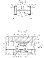
- Fig. 1 shows, highly diagrammatically, a double diaphragm pump having two cavities 1 and 2, each of which is subdivided by a diaphragm into a pump chamber and a drive chamber.
- Cavity 1 is subdivided by diaphragm 7 into a pump chamber 3 and a drive chamber 4
- cavity 2 is subdivided by diaphragm 8 into a pump chamber 6 and a drive chamber 5.
- the diaphragms 7 and 8 form the so-called pump elements.
- Fluid or medium to be pumped is drawn towards the pump chambers via lines 9 and 10 in order then to be discharged from the pump chambers via lines 11 and 12.
- Drive fluid such as compressed air or a liquid, is fed to the control valve 20 via line 13.
- the control valve 20 is connected, via line 15, with the drive chamber 4 and, via line 16, with the drive chamber 5.
- the control valve 20 is further provided with a return line 17 for drive fluid.
- the diaphragms 7 and 8 are connected to one another by means of a rod 14 to enable them to move in tandem. By moving the rod 14 alternately to the right and to the left it is possible to achieve alternate pumping of fluid from the one cavity 1 whilst fluid is drawn into the other cavity 2.
- Figure 1 shows the diaphragms in the position where they have been moved fully to the right. In this position the pump chamber 3 has been emptied as far as possible by driving off the fluid contained therein, via line 12, whilst the pump chamber 6 is completely filled by drawing in fluid to be pumped, via line 9.
- Switching valves of this type are provided with a slide which, via a coupling with the rod 14, is movable to and fro between two end positions such that when the rod 14 is moved to the right line 13 is connected to line 15 and line 16 is connected to line 17 until, on reaching the right-hand end position, the slide is automatically switched over, after which line 13 is connected to line 16 and line 15 is connected to line 17.
- the movement of the rod 14 will now be reversed and take place to the left until the rod 14 approaches the left-hand end position, the slide again being automatically switched over such that line 13 is connected to line 15 and line 16 is connected to line 17.
- this is a wholly mechanical, automatic switching process.
- the known switching valves display a number of disadvantages. They are not usable under diverse operating conditions from very low to very high switching frequencies and/or they are not usable in every environment.
- the double diaphragm pump according to the invention which is thus obtained is usable in a reliable manner at both low and high switching frequencies and in very diverse environments.
- a control valve according to the invention can also be used highly advantageously in a so-called double-acting piston pump and in a so-called double-acting bellows pump.
- the pump elements 7, 8 (which in the case of Fig. 1 are formed by diaphragms in a diaphragm pump) must be replaced by pistons, which are movable to and fro in the cavities 1 and 2.
- the cavities 1 and 2 in this case form the cylinders of double-acting piston pumps.
- a so-called bellows pump is obtained by replacing the pump elements 7 and 8 in diaphragm form in Fig. 1 by bellows.
- a coupling between the operating rod 14 and the slide which coupling consists of at least one, preferably rigid, arm and at least one resiliently compressible element.
- the arm has a first hinge point which can be carried along by the operating rod 14 and a second hinge point which can be carried along by the slide.
- the distance between the operating rod and the slide viewed perpendicular to the longitudinal direction of the operating rod, remains unchanged.
- 14 is the operating rod, 21 the first hinge, 22 the second hinge, which in this example is fixed relative to the slide, which is not shown, 23 is the arm and 24 is a compressible, resilient element.
- the compressible, resilient element 24 is accommodated in the arm between the first and the second hinge, which arm 23 is preferably rigid in its transverse direction.
- said resilient element 24 can also be arranged between the first hinge point 21 and the operating rod 14 and/or between the second hinge point 22 and the slide.
- a compressible element 24 it is also certainly conceivable to construct the arm such that it is itself deformable, for example compressible or bendable.
- FIG. 4a shows the slide, which is not shown, in the right-hand end position and the operating rod 14 is moved to the right in accordance with arrow A.
- the second hinge point 22 remains in place and the first hinge point 21 is moved to the right until said first hinge point 21 is lying below the second hinge point 22.
- Figure 4b shows the point in time at which the so-called dead point is reached, at which dead point the first hinge point 21 and the second hinge point 22 are on one line, which is perpendicular to the longitudinal direction or direction of movement of the operating rod 14.
- the vertical distance between the first and the second hinge point that is to say the distance viewed perpendicularly to the direction of movement of the operating rod 14, is unchanged.
- the arm 23 becomes shorter as a consequence of the compression of the compressible, resilient element 24.
- the resilient, compressible element 24 were to be arranged between the first hinge point 21 and the operating rod 14.
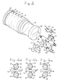
- FIG. 2 An advantageous embodiment of a switching valve according to the invention is shown diagrammatically in Figures 2 and 3. With a view to clarity, the lines 13, 15, 16, 17 and the operating rod 14 have been given the same reference numerals in these figures as in Fig. 1.
- the switching valve 20 consists of a casing 31 with a slide 32 therein which is slidable to and fro between two end positions. The right-hand end position is delimited by a stop 33 and the left-hand end position is delimited by a stop 34. In the right-hand position of the slide 32, which is shown, line 13 is connected via the cavity 35, delimited by the slide 32 and the casing 31, to line 15. In this position, line 16 is connected via the casing to line 17. It will be clear that when the slide 32 is in its left-hand position delimited by the stop 34, line 13 is connected to line 16 and line 15 is connected to line 17.
- the operating rod 14 is provided with grooved notches 36 at two points on either side.
- the bases of each groove 37 act as a support point for a knife edge 38 on an arm 39, which is preferably essentially rigid.
- the groove base 37 and knife edge 38 together form the first hinge point of the arm 39.
- the second hinge point of the arm 39 is formed by a knife edge 40 and groove 41, which is formed in a yoke 42.
- the yoke 42 is provided with a recess 43, which extends between two parallel arms 39.
- a compressible, resilient element 44 is accommodated in said recess 43.
- Each yoke 42 and compressible, resilient element 44 is fixed in the axial direction C with respect to the slide 32.
- auxiliary frame which consists of a U-shaped frame section 50 and a plate-shaped frame section 51.
- the cover section 51 of the frame is then placed over the U-shaped frame section.
- the shape of the outer periphery of the assembled frame 50, 51 corresponds to the shape of the inner periphery of the recess 53 in the slide 32.
- the assembled whole comprising operating shaft, coupling and frame can be slid into the recess 53 until the stop ridges 54 and 55 on the frame 50, 51 engage behind the edges 56 on the front ends of the passage 53.
- Fig. 5 shows, highly diagrammatically, an operating principle of a so-called double, double-acting plunger pump. Since the functioning of said double, double-acting plunger pump corresponds in broad terms to that of the double-acting diaphragm pump according to Fig. 1, the same numbers have been used for corresponding reference numerals, with the suffix a. Thus, with respect to the functioning reference can be made essentially to Fig. 1. Only a brief explanation of the differences will be given here.
- the pump elements 7a and 8a are formed by plungers, which are movable to and fro in accordance with arrow C in respective cylinders 2a and 1a.
- the plungers 7a and 8a are rigidly coupled to one another by a connecting rod 70a, with the operating rod 14a for the control valve 20a fixed thereto.
- the operating rod 14a will in this case be movable to and fro together with the pumping movement of the plungers. Since the plungers are rigidly coupled, they will move in the same direction in this case. This means that when the drive chamber of the one cylinder is actuated in order to pump empty the pump chamber of said cylinder, the drive chamber of the other cylinder is not actuated, so that the drive fluid can be driven therefrom and the pump chamber belonging to the other cylinder can, as a result of the suction action, be filled with fluid to be pumped.
- Fig. 6 shows, highly diagrammatically, an operating principle of a single plunger pump, provided with a control valve according to the invention. Since in this case as well the functioning in broad terms corresponds to that of the double diaphragm pump according to Fig. 1, here again the same reference numerals are used with the suffix b.
- the one pump element is always brought back to its initial position in accordance with pumping by actuation of the drive chamber for the other pump element.
- the second drive chamber is lacking.
- a spring 71b (or 71c in the case of Fig. 7) is provided in these cases.
- the control valve 20b in this case does not have to switch between two drive chambers, but has alternately to actuate and to relieve only one drive chamber. Therefore a line equivalent to line 16 in Fig. 1 can be dispensed with.
- the plunger 7b is connected, via a rod 70b rigidly attached thereto, to the operating rod 14b for the control valve 20b. When the plunger 7b moves to and fro in accordance with arrow C, the operating rod 14b for the control valve 20b will also move to and fro in accordance with arrow C.
- control valve 20b actuates drive chamber 4b (line 13b and line 15b are then connected to one another), the plunger 7b is driven to the right and pumps the pump chamber 3b empty via line 12b.
- the switching valve 20b will shut line 13b and connect line 15b to line 17b.
- the drive chamber 4b is then relieved and the spring 71b will drive back the plunger 7b, during which operation, in the meantime, the pump chamber 3b is filled with fluid to be pumped by suction via line 10b.
- the control valve 20b will be switched over again. Line 13b will then be connected to line 15b again, after which the cycle just described can repeat.
- Fig. 7 shows a single-acting piston pump provided with a control valve according to the invention.
- the functioning of said single-acting piston pump is completely identical to that of the plunger pump according to Fig. 6.
- the reference numerals are therefore identical, except that the letter b has been replaced by letter c for differentiation.
- the operating rod 14c is in this case integrated with the piston rod for the piston 7c, which in this case forms the pump element.
- the piston 7c can very readily be replaced by a diaphragm or a bellows. A diaphragm pump or a bellows pump will then be obtained.
- control valve and diaphragm pump according to the invention are conceivable within the scope of the invention.
- three or more parallel arms Reference has always been made above to one arm 39 with a knife edge 40 which engages in a groove base 37.
- the yoke with a protrusion which engages in a groove on the end of the arm.
- fix the element 44 with respect to the operating rod instead of with respect to the slide.
- construct the yokes 42 such that they are resiliently bendable, in which case the elements 44 can then be dispensed with.
Landscapes
- Engineering & Computer Science (AREA)
- Mechanical Engineering (AREA)
- General Engineering & Computer Science (AREA)
- Reciprocating Pumps (AREA)
- Massaging Devices (AREA)
- Vehicle Body Suspensions (AREA)
Applications Claiming Priority (2)
| Application Number | Priority Date | Filing Date | Title |
|---|---|---|---|
| NL1001954A NL1001954C2 (nl) | 1995-12-21 | 1995-12-21 | Stuurklep en pomp voorzien van stuurklep. |
| NL1001954 | 1995-12-21 |
Publications (1)
| Publication Number | Publication Date |
|---|---|
| EP0780574A1 true EP0780574A1 (fr) | 1997-06-25 |
Family
ID=19762066
Family Applications (1)
| Application Number | Title | Priority Date | Filing Date |
|---|---|---|---|
| EP96203655A Withdrawn EP0780574A1 (fr) | 1995-12-21 | 1996-12-20 | Clapet de commande et pompe avec un clapet de commande |
Country Status (3)
| Country | Link |
|---|---|
| EP (1) | EP0780574A1 (fr) |
| NL (1) | NL1001954C2 (fr) |
| NO (1) | NO965536L (fr) |
Cited By (3)
| Publication number | Priority date | Publication date | Assignee | Title |
|---|---|---|---|---|
| WO2010099299A1 (fr) * | 2009-02-25 | 2010-09-02 | Idex Aodd, Inc. | Pompe à double membrane pneumatique comportant une soupape décentrée |
| DE202010004957U1 (de) * | 2010-04-12 | 2011-08-26 | Timmer-Pneumatik Gmbh | Fluid-Steuerventilsystem für eine Pumpensteuerung |
| WO2011116061A1 (fr) * | 2010-03-19 | 2011-09-22 | Illinois Tool Works Inc. | Tringlerie décentrée |
Citations (7)
| Publication number | Priority date | Publication date | Assignee | Title |
|---|---|---|---|---|
| BE489001A (fr) * | ||||
| DE2726674B1 (de) * | 1977-06-14 | 1978-05-18 | Draegerwerk Ag | Druckgasbetaetigte Doppelmembranpumpe |
| US4354806A (en) * | 1980-01-29 | 1982-10-19 | The Coca-Cola Company | Pneumatically powerable double acting positive displacement fluid pump |
| DE3310131A1 (de) | 1983-03-21 | 1984-09-27 | DEPA Gesellschaft für Verfahrenstechnik mbH, 4000 Düsseldorf | Umsteuerventileinsatz fuer eine druckluftgetriebene doppelmembranpumpe |
| EP0321573A1 (fr) * | 1987-05-28 | 1989-06-28 | Yamada Yuki Seizo Co. Ltd. | Structure de commutation a mouvement alternatif pour pompes |
| US5308230A (en) * | 1993-03-08 | 1994-05-03 | Stainless Steel Products, Inc. | Bellows pump |
| EP0480192B1 (fr) | 1990-10-08 | 1994-07-13 | ALMATEC Technische Innovationen GmbH | Pompe à double membrane |
-
1995
- 1995-12-21 NL NL1001954A patent/NL1001954C2/nl not_active IP Right Cessation
-
1996
- 1996-12-20 EP EP96203655A patent/EP0780574A1/fr not_active Withdrawn
- 1996-12-20 NO NO965536A patent/NO965536L/no unknown
Patent Citations (8)
| Publication number | Priority date | Publication date | Assignee | Title |
|---|---|---|---|---|
| BE489001A (fr) * | ||||
| DE2726674B1 (de) * | 1977-06-14 | 1978-05-18 | Draegerwerk Ag | Druckgasbetaetigte Doppelmembranpumpe |
| US4354806A (en) * | 1980-01-29 | 1982-10-19 | The Coca-Cola Company | Pneumatically powerable double acting positive displacement fluid pump |
| DE3310131A1 (de) | 1983-03-21 | 1984-09-27 | DEPA Gesellschaft für Verfahrenstechnik mbH, 4000 Düsseldorf | Umsteuerventileinsatz fuer eine druckluftgetriebene doppelmembranpumpe |
| EP0321573A1 (fr) * | 1987-05-28 | 1989-06-28 | Yamada Yuki Seizo Co. Ltd. | Structure de commutation a mouvement alternatif pour pompes |
| EP0508555A2 (fr) * | 1987-05-28 | 1992-10-14 | Yamada Yuki Seizo Co. Ltd. | Structure de commutation à mouvement alternatif pour pompes |
| EP0480192B1 (fr) | 1990-10-08 | 1994-07-13 | ALMATEC Technische Innovationen GmbH | Pompe à double membrane |
| US5308230A (en) * | 1993-03-08 | 1994-05-03 | Stainless Steel Products, Inc. | Bellows pump |
Cited By (8)
| Publication number | Priority date | Publication date | Assignee | Title |
|---|---|---|---|---|
| WO2010099299A1 (fr) * | 2009-02-25 | 2010-09-02 | Idex Aodd, Inc. | Pompe à double membrane pneumatique comportant une soupape décentrée |
| WO2011116061A1 (fr) * | 2010-03-19 | 2011-09-22 | Illinois Tool Works Inc. | Tringlerie décentrée |
| CN102947588A (zh) * | 2010-03-19 | 2013-02-27 | 伊利诺斯器械工程公司 | 偏心连接 |
| RU2543372C2 (ru) * | 2010-03-19 | 2015-02-27 | Иллинойс Тул Воркс Инк. | Двухдиафрагменный насос с пневмоприводом |
| CN102947588B (zh) * | 2010-03-19 | 2015-11-25 | 菲尼逊品牌控股有限公司 | 压缩空气驱动的双隔膜泵 |
| US9447780B2 (en) | 2010-03-19 | 2016-09-20 | Carlisle Fluid Technologies, Inc. | Over-center linkage |
| US9903360B2 (en) | 2010-03-19 | 2018-02-27 | Carlisle Fluid Technologies, Inc. | Over-center linkage |
| DE202010004957U1 (de) * | 2010-04-12 | 2011-08-26 | Timmer-Pneumatik Gmbh | Fluid-Steuerventilsystem für eine Pumpensteuerung |
Also Published As
| Publication number | Publication date |
|---|---|
| NO965536D0 (no) | 1996-12-20 |
| NO965536L (no) | 1997-06-23 |
| NL1001954C2 (nl) | 1997-06-24 |
Similar Documents
| Publication | Publication Date | Title |
|---|---|---|
| US4436493A (en) | Self contained pump and reversing mechanism therefor | |
| US5033943A (en) | Low fluid shear pump | |
| EP0304210B1 (fr) | Pompe à double membrane | |
| CA1056208A (fr) | Pompe doseuse a double effet | |
| EP0823023B1 (fr) | Pompe a double effet | |
| JPS6251764A (ja) | 制量ポンプ | |
| US12320341B2 (en) | Micro piston pump | |
| US4610192A (en) | Reciprocable device | |
| US5104299A (en) | Electromagnetic reciprocating pump | |
| CN110617200B (zh) | 流体泵和相关的系统和方法 | |
| EP0780574A1 (fr) | Clapet de commande et pompe avec un clapet de commande | |
| US4271989A (en) | Micro-metering system | |
| US11293421B2 (en) | Apparatus for reducing suction pulsation and swash plate type compressor comprising same | |
| US6145541A (en) | Four-way selector valve | |
| US5758563A (en) | Fluid driven reciprocating pump | |
| US4634350A (en) | Double acting diaphragm pump and reversing mechanism therefor | |
| CN102016317B (zh) | 一种改进的液压驱动机器 | |
| NZ194940A (en) | Reciprocating pump reversing mechanism | |
| JP4455713B2 (ja) | 弁ユニット及びそれを用いた送液ポンプ | |
| US4509402A (en) | Magnetic reversing mechanism | |
| US20250250975A1 (en) | Multiple displacement pump | |
| CN113446211A (zh) | 液压元件和具有这种元件的排量泵 | |
| US20260126037A1 (en) | Multiple displacement pump | |
| WO2019186377A1 (fr) | Système de soupape anti-calage bistable | |
| WO1997011275A1 (fr) | Pompe et son procede de fabrication |
Legal Events
| Date | Code | Title | Description |
|---|---|---|---|
| PUAI | Public reference made under article 153(3) epc to a published international application that has entered the european phase |
Free format text: ORIGINAL CODE: 0009012 |
|
| AK | Designated contracting states |
Kind code of ref document: A1 Designated state(s): AT BE CH DE DK ES FI FR GB GR IE IT LI LU MC NL PT SE |
|
| 17P | Request for examination filed |
Effective date: 19971222 |
|
| STAA | Information on the status of an ep patent application or granted ep patent |
Free format text: STATUS: THE APPLICATION IS DEEMED TO BE WITHDRAWN |
|
| 18D | Application deemed to be withdrawn |
Effective date: 19990701 |