EP0780580B1 - Dispositif pour générer des variations périodiques d'impulsions dans un courant de fluide, méthode pour l'opération du dispositif et utilisation de celui-ci - Google Patents
Dispositif pour générer des variations périodiques d'impulsions dans un courant de fluide, méthode pour l'opération du dispositif et utilisation de celui-ci Download PDFInfo
- Publication number
- EP0780580B1 EP0780580B1 EP95810815A EP95810815A EP0780580B1 EP 0780580 B1 EP0780580 B1 EP 0780580B1 EP 95810815 A EP95810815 A EP 95810815A EP 95810815 A EP95810815 A EP 95810815A EP 0780580 B1 EP0780580 B1 EP 0780580B1
- Authority
- EP
- European Patent Office
- Prior art keywords
- pressure
- flow section
- window
- pressure line
- inlet flow
- Prior art date
- Legal status (The legal status is an assumption and is not a legal conclusion. Google has not performed a legal analysis and makes no representation as to the accuracy of the status listed.)
- Expired - Lifetime
Links
- 238000000034 method Methods 0.000 title claims description 17
- 239000012530 fluid Substances 0.000 title claims description 12
- 230000000737 periodic effect Effects 0.000 title description 6
- 239000012528 membrane Substances 0.000 claims description 12
- 230000010349 pulsation Effects 0.000 claims description 6
- 239000000463 material Substances 0.000 claims description 4
- 230000008569 process Effects 0.000 claims description 3
- 230000031018 biological processes and functions Effects 0.000 claims description 2
- 238000011144 upstream manufacturing Methods 0.000 claims description 2
- 238000009423 ventilation Methods 0.000 claims description 2
- 239000007789 gas Substances 0.000 claims 3
- 238000000855 fermentation Methods 0.000 claims 1
- 230000004151 fermentation Effects 0.000 claims 1
- XLYOFNOQVPJJNP-UHFFFAOYSA-N water Substances O XLYOFNOQVPJJNP-UHFFFAOYSA-N 0.000 description 7
- 229920001971 elastomer Polymers 0.000 description 4
- 230000015572 biosynthetic process Effects 0.000 description 2
- 230000008859 change Effects 0.000 description 2
- 238000002474 experimental method Methods 0.000 description 2
- 230000002349 favourable effect Effects 0.000 description 2
- 238000012423 maintenance Methods 0.000 description 2
- 230000010355 oscillation Effects 0.000 description 2
- 230000009467 reduction Effects 0.000 description 2
- 230000001105 regulatory effect Effects 0.000 description 2
- 230000006978 adaptation Effects 0.000 description 1
- 230000008901 benefit Effects 0.000 description 1
- 229920005549 butyl rubber Polymers 0.000 description 1
- 239000003795 chemical substances by application Substances 0.000 description 1
- 230000001419 dependent effect Effects 0.000 description 1
- 238000011161 development Methods 0.000 description 1
- 230000018109 developmental process Effects 0.000 description 1
- 238000010586 diagram Methods 0.000 description 1
- 230000000694 effects Effects 0.000 description 1
- 239000011521 glass Substances 0.000 description 1
- 239000007788 liquid Substances 0.000 description 1
- 238000004519 manufacturing process Methods 0.000 description 1
- 239000010865 sewage Substances 0.000 description 1
- 238000012360 testing method Methods 0.000 description 1
- 230000032258 transport Effects 0.000 description 1
Images
Classifications
-
- F—MECHANICAL ENGINEERING; LIGHTING; HEATING; WEAPONS; BLASTING
- F16—ENGINEERING ELEMENTS AND UNITS; GENERAL MEASURES FOR PRODUCING AND MAINTAINING EFFECTIVE FUNCTIONING OF MACHINES OR INSTALLATIONS; THERMAL INSULATION IN GENERAL
- F16L—PIPES; JOINTS OR FITTINGS FOR PIPES; SUPPORTS FOR PIPES, CABLES OR PROTECTIVE TUBING; MEANS FOR THERMAL INSULATION IN GENERAL
- F16L55/00—Devices or appurtenances for use in, or in connection with, pipes or pipe systems
- F16L55/04—Devices damping pulsations or vibrations in fluids
- F16L55/045—Devices damping pulsations or vibrations in fluids specially adapted to prevent or minimise the effects of water hammer
- F16L55/05—Buffers therefor
- F16L55/052—Pneumatic reservoirs
- F16L55/053—Pneumatic reservoirs the gas in the reservoir being separated from the fluid in the pipe
- F16L55/054—Pneumatic reservoirs the gas in the reservoir being separated from the fluid in the pipe the reservoir being placed in or around the pipe from which it is separated by a sleeve-shaped membrane
-
- F—MECHANICAL ENGINEERING; LIGHTING; HEATING; WEAPONS; BLASTING
- F16—ENGINEERING ELEMENTS AND UNITS; GENERAL MEASURES FOR PRODUCING AND MAINTAINING EFFECTIVE FUNCTIONING OF MACHINES OR INSTALLATIONS; THERMAL INSULATION IN GENERAL
- F16L—PIPES; JOINTS OR FITTINGS FOR PIPES; SUPPORTS FOR PIPES, CABLES OR PROTECTIVE TUBING; MEANS FOR THERMAL INSULATION IN GENERAL
- F16L55/00—Devices or appurtenances for use in, or in connection with, pipes or pipe systems
- F16L55/04—Devices damping pulsations or vibrations in fluids
-
- Y—GENERAL TAGGING OF NEW TECHNOLOGICAL DEVELOPMENTS; GENERAL TAGGING OF CROSS-SECTIONAL TECHNOLOGIES SPANNING OVER SEVERAL SECTIONS OF THE IPC; TECHNICAL SUBJECTS COVERED BY FORMER USPC CROSS-REFERENCE ART COLLECTIONS [XRACs] AND DIGESTS
- Y10—TECHNICAL SUBJECTS COVERED BY FORMER USPC
- Y10T—TECHNICAL SUBJECTS COVERED BY FORMER US CLASSIFICATION
- Y10T137/00—Fluid handling
- Y10T137/206—Flow affected by fluid contact, energy field or coanda effect [e.g., pure fluid device or system]
- Y10T137/218—Means to regulate or vary operation of device
- Y10T137/2185—To vary frequency of pulses or oscillations
Definitions
- the present invention relates to a device according to the preamble of claim 3 and on a The method of claim 1 and the use of the device according to claims 7 to 10.
- Fluid dynamics are often periodically pulsating Flows necessary around any mixing operations and / or to achieve targeted flow effects or detachments from Media.
- the subject of the invention is said to be economical be producible and require minimal maintenance. It should also be easily integrated into a pressure line to let.
- pressure used in the claim can both related to the environment, an overpressure, as well as a negative pressure (Vacuum) be on the elastic pontic acts.
- the subject of the invention causes periodic vibrations, which are periodic, low-frequency in the outflow section Induce pressure vibrations; a strongly pulsating arises Flow leading to cavitation (vapor bubble formation) can lead.
- the elastic intermediate member creates a pressure in the fluid imprinted, which according to the notoriously known Bernoulli equation set energy balance within of the steady flow.
- the elastic intermediate member becomes the continuity of the mass and energy flow temporarily disturbed, i.e. these are destabilized, so that a fluid-mechanical resonant circuit is created.
- the resulting pulse frequency is accordingly of the mechanical parameters of the system and shows the Properties of a resonance circuit.
- a membrane-like intermediate member according to claim 3 allowed an easy to implement adaptation to existing configurations and piping systems.
- the dimensioning of the intermediate link or the window can be taken from claim 4, the window size upwards through the necessary fastening of the membrane on Inflow section is limited.
- the pulsation stroke (amplitude) can be easily enlarge.
- the pulsation stroke of the fluid can also be optimized.
- a process according to is particularly simple and economical Claim 1, which no auxiliary units, such as additional Pressure sources, compressors etc. required.
- swirl rings for example, serves air transportation in air-conditioned rooms; it results Air parcels.
- the use of the device in connection is particularly favorable with biological processes, such as those which run in a sewage treatment plant, claim 8.
- the high pulse power enables the support of solution and mixing operations, claim 9, even in cases of previously used ultrasonic and / or special stirrers made necessary.
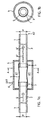
- Fig. 1a 1 is a conventional pressure line of a pressure medium network, referred to, for example, a compressed air network; the pressure line 1 has a constant inner diameter d on.
- Part A2 of the outflow section serves as the outflow nozzle.
- a hollow body placed pressure-tight on section 2 a pressure chamber 4, which has an elastic intermediate member 5 contains.
- the intermediate link 5 is in turn on a rotating Fixing point 7 attached gas-tight in a known manner and in the same way with a subsequent outflow section 3 of the pressure line 1, the same diameter d connected.
- the pressure chamber 4 also has a control connection 6 on, which allows the intermediate member 5 with a pressure p3 to act upon.
- FIG. 1b shows the concentric arrangement Fig. 1a again.
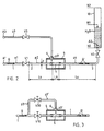
- a ventilation device has a vessel 10 on; the vessel bottom is at the zero level N0, it is filled with water, the current filling level is N1, the maximum Fill level is designated N2.
- N1 the maximum Fill level
- the nozzle A2 is a shut-off reducing valve V2 upstream.
- a pressure line 1 is provided with a connection A1 which is connected to a pressure source, not shown, wherein this pressure line 1 in turn by an inner diameter d and a fluid flow Q and a network pressure p1 is characterized.
- a first shut-off reducing valve is V1 at a distance Lz from the right-hand end of the inflow section 2 remote; the line length in the outflow section 3 to the second shut-off reducing valve V2 La. The distance between the two sections, i.e. the active length of the intermediate member 5 is LA.
- the intermediate member 5 is enclosed by a hollow body 4, in which a control connection 6 opens.
- a line is connected to the control connection 6, which after a control pressure regulating valve V3 a control pressure p3 '.
- An external one serves as the control source Port A3, which with any pressure source connected is.
- FIG. 3 has a simplified arrangement compared to FIG again a pressure line 1 with a flow Q, of which a bypass branches off which has a control pressure p3, which is reduced to size p3 'via a reducing valve V30 becomes. Another is located within the pressure line 1 Reducing valve V10; the rest of the arrangement is analogous to FIG. 2 educated.
- the inner diameter d of the pressure line was 26 mm; the active Length LA of the intermediate link 100 mm; the line length in the inflow section 1,000 mm; the line length La in the outflow section 550 mm and the diameter of the choke acting nozzle A2 was 13 mm.
- Typical basic frequencies from 30 Hz to 400 Hz could be found Set, with the network pressure p1 from 2.0 bar to 8.0 bar and the control pressure p3 'varies from 10 mbar to 300 mbar were.
- the resulting pulsation frequency generated with an analog one Device, was only 5 to 25 Hz the control pressure p3 'was varied between 10 to 500 mbar.
- the network pressure was 2 to 8 bar.
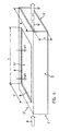
- channel-shaped fluids can be periodically control their flow, cf. Fig. 4.
- a common channel is as a support 9 for an intermediate member 5 ' formed and has a box-shaped inflow section 2 'and a similar outflow section 3'.
- the Flow height is denoted by h; the flow width with b.
- h the flow width
- b the flow width
- In the upper wall of the carrier 9 is a rectangular one Window 8 cut out, with an opening length c and one Width b '. This window 8 is closed in a pressure-tight manner a rubber membrane 5 ', which in a suitable manner with a Control pressure p3 is applied.
- the channel-shaped carrier 9 has the advantage that a connection for the control pressure p3, due to the flat surfaces, very easily via flanges and / or directly via pipes is feedable.
Landscapes
- Engineering & Computer Science (AREA)
- General Engineering & Computer Science (AREA)
- Mechanical Engineering (AREA)
- Reciprocating Pumps (AREA)
- Fluid-Pressure Circuits (AREA)
- Pipe Accessories (AREA)
Claims (10)
- Procédé pour produire un courant à pulsations périodiques dans une conduite sous pression au moyen d'un dispositif constitué
d'un tronçon d'arrivée se trouvant dans la conduite sous pression et d'un tronçon d'écoulement,
d'un organe intermédiaire avec
une membrane constituée d'une matière élastique résistant à la pression et
des moyens pour exercer une pression sur l'organe intermédiaire,
caractérisé en ce que le tronçon d'arrivée est raccordé à un réseau de pression et en ce que l'organe intermédiaire est soumis à une pression de commande constante ou variable, de sorte qu'il en résulte une fréquence de pulsations dans le tronçon d'écoulement comprise entre 5 Hz et 400 Hz. - Procédé selon la revendication 1, caractérisé en ce que dans la conduite sous pression, dans le tronçon d'arrivée, il est prévu un organe d'étranglement, en ce qu'en amont de cet organe d'étranglement une veine d'écoulement est prélevée de la conduite sous pression et acheminée vers l'organe intermédiaire.
- Dispositif pour produire un courant à pulsations périodiques dans une conduite sous pression constitué
d'un tronçon d'arrivée (2') se trouvant dans la conduite sous pression et d'un tronçon d'écoulement (3'),
d'un organe intermédiaire (5') avec
une membrane constituée d'une matière élastique résistant à la pression et
des moyens pour exercer une pression sur l'organe intermédiaire,
caractérisé en ce qu'au moins le tronçon d'arrivée (2') est en forme de caisson, en ce que dans une partie de support (9) suivante est découpée, dans le sens d'écoulement, au moins une fenêtre (8), en ce que cette fenêtre (8) est fermée de manière étanche par une membrane élastique (5'), et en ce que la pression extérieure (p3) agit sur cette membrane (5'), la fenêtre convenant, en raison de sa conformation plane, comme moyen de raccordement pour l'alimentation en pression à partir d'un système de conduites. - Dispositif selon la revendication 3, caractérisé en ce que le tronçon d'arrivée (2') présente une largeur (b) qui est un multiple de sa hauteur (h) et en ce que la fenêtre (8) présente une largeur (b') qui représente au moins 0,7 fois la largeur (b) et en ce que la longueur (c) de cette fenêtre (8) correspond au moins à la valeur de la hauteur (h) de la partie de support (9).
- Dispositif selon la revendication 3 ou 4, caractérisé en ce que dans la partie de support (9) sont prévues au moins deux fenêtres (8) disposées l'une face à l'autre.
- Dispositif selon la revendication 5, caractérisé en ce que la capacité de déformation des membranes (5') est choisie de manière qu'à l'état sollicité et/ou en fonctionnement, elles se touchent l'une l'autre.
- Utilisation du procédé selon l'une des revendications 1 ou 2, pour former des anneaux de tourbillonnement.
- Utilisation du procédé selon l'une des revendications 1 ou 2, pour aérer des installations de fermentation et/ou des processus biologiques aérobies.
- Utilisation du procédé selon l'une des revendications 1 ou 2, pour favoriser des processus de dissolution et de mélange tels que de gaz à gaz ou de gaz à liquide ou de liquide à liquide.
- Utilisation du procédé selon l'une des revendications 1 ou 2, pour réduire la consommation d'air dans des dispositifs de transport à coussins d'air.
Priority Applications (4)
| Application Number | Priority Date | Filing Date | Title |
|---|---|---|---|
| DE59510556T DE59510556D1 (de) | 1995-12-22 | 1995-12-22 | Vorrichtung zur Erzeugung von periodischen Impulsänderungen in einer Fluid-Strömung, Verfahren zum Betrieb der Vorrichtung und deren Verwendung |
| EP95810815A EP0780580B1 (fr) | 1995-12-22 | 1995-12-22 | Dispositif pour générer des variations périodiques d'impulsions dans un courant de fluide, méthode pour l'opération du dispositif et utilisation de celui-ci |
| US08/769,232 US5819801A (en) | 1995-12-22 | 1996-12-18 | Method and device for producing periodical impulse changes in a fluid flow |
| JP8341668A JPH09196015A (ja) | 1995-12-22 | 1996-12-20 | 流体流中で周期的インパルス変化を生成させるための装置、及び同装置の操作方法 |
Applications Claiming Priority (1)
| Application Number | Priority Date | Filing Date | Title |
|---|---|---|---|
| EP95810815A EP0780580B1 (fr) | 1995-12-22 | 1995-12-22 | Dispositif pour générer des variations périodiques d'impulsions dans un courant de fluide, méthode pour l'opération du dispositif et utilisation de celui-ci |
Publications (2)
| Publication Number | Publication Date |
|---|---|
| EP0780580A1 EP0780580A1 (fr) | 1997-06-25 |
| EP0780580B1 true EP0780580B1 (fr) | 2003-02-12 |
Family
ID=8221836
Family Applications (1)
| Application Number | Title | Priority Date | Filing Date |
|---|---|---|---|
| EP95810815A Expired - Lifetime EP0780580B1 (fr) | 1995-12-22 | 1995-12-22 | Dispositif pour générer des variations périodiques d'impulsions dans un courant de fluide, méthode pour l'opération du dispositif et utilisation de celui-ci |
Country Status (4)
| Country | Link |
|---|---|
| US (1) | US5819801A (fr) |
| EP (1) | EP0780580B1 (fr) |
| JP (1) | JPH09196015A (fr) |
| DE (1) | DE59510556D1 (fr) |
Families Citing this family (12)
| Publication number | Priority date | Publication date | Assignee | Title |
|---|---|---|---|---|
| US6125843A (en) * | 1997-09-04 | 2000-10-03 | Pincgold Llc | Liquid spray dispenser and method |
| US6085762A (en) * | 1998-03-30 | 2000-07-11 | The Regents Of The University Of California | Apparatus and method for providing pulsed fluids |
| KR100557247B1 (ko) * | 1998-03-30 | 2006-03-07 | 더 리젠츠 오브 더 유니버시티 오브 캘리포니아 | 맥동 유체를 제공하기 위한 장치 및 방법 |
| GB0208840D0 (en) * | 2002-04-18 | 2002-05-29 | Novamedix Distrib Ltd | Fluid control valve |
| US8118784B2 (en) * | 2007-10-30 | 2012-02-21 | Cook Medical Technologies Llc | Haemostatic valve |
| US8657794B2 (en) * | 2009-10-08 | 2014-02-25 | Skylab Development, Inc. | High flow volume nasal irrigation device and method for alternating pulsatile and continuous fluid flow |
| US7976529B2 (en) * | 2009-10-08 | 2011-07-12 | Skylab Developments Inc. | High flow volume nasal irrigation device and method for alternating pulsatile and continuous fluid flow |
| CN102506111A (zh) * | 2011-11-09 | 2012-06-20 | 中联重科股份有限公司 | 弹性阻尼器、布料臂架及混凝土布料设备 |
| CN102494221B (zh) * | 2011-12-07 | 2014-04-16 | 中联重科股份有限公司 | 弹性阻尼器、布料臂架及混凝土布料设备 |
| DE102012007376A1 (de) * | 2012-04-12 | 2013-10-17 | Daimler Ag | Vorrichtung zur Brennstoffversorgung einer Brennstoffzelle |
| CN105276224A (zh) * | 2015-10-16 | 2016-01-27 | 吴忠仪表有限责任公司 | 铁路卫生阀用高密封结构的夹管阀 |
| US10254770B2 (en) * | 2015-11-20 | 2019-04-09 | Massachusetts Institute Of Technology | Low-pressure and low-energy self-regulating valve |
Family Cites Families (6)
| Publication number | Priority date | Publication date | Assignee | Title |
|---|---|---|---|---|
| US2014355A (en) * | 1933-02-27 | 1935-09-10 | United States Gypsum Co | Vibration isolating pipe connection |
| US2590215A (en) * | 1947-02-21 | 1952-03-25 | Frank C Sausa | Variable throat restricter valve |
| US3387630A (en) * | 1965-04-22 | 1968-06-11 | Dow Chemical Co | Adjustable pressure reducing device |
| US4135550A (en) * | 1977-03-11 | 1979-01-23 | Trelleborg Rubber Company, Inc. | Pinch valve control circuit |
| JPS616494A (ja) * | 1984-06-20 | 1986-01-13 | 東海ゴム工業株式会社 | 脈動吸収ホ−ス |
| DE4240323C2 (de) * | 1992-12-01 | 1996-02-29 | Grohe Armaturen Friedrich | Geräuschdämpfungseinsatz für Sanitärarmaturen |
-
1995
- 1995-12-22 EP EP95810815A patent/EP0780580B1/fr not_active Expired - Lifetime
- 1995-12-22 DE DE59510556T patent/DE59510556D1/de not_active Expired - Fee Related
-
1996
- 1996-12-18 US US08/769,232 patent/US5819801A/en not_active Expired - Fee Related
- 1996-12-20 JP JP8341668A patent/JPH09196015A/ja active Pending
Also Published As
| Publication number | Publication date |
|---|---|
| JPH09196015A (ja) | 1997-07-29 |
| US5819801A (en) | 1998-10-13 |
| EP0780580A1 (fr) | 1997-06-25 |
| DE59510556D1 (de) | 2003-03-20 |
Similar Documents
| Publication | Publication Date | Title |
|---|---|---|
| DE4126397C2 (de) | Verfahren und Vorrichtung zur Schaumerzeugung | |
| EP0780580A1 (fr) | Dispositif pour générer des variations périodiques d'impulsions dans un courant de fluide, méthode pour l'opération du dispositif et utilisation de celui-ci | |
| WO2007131594A1 (fr) | Mélangeur vibratoire | |
| EP0367001A1 (fr) | Réservoir de combustible pour le stockage des liquides agressifs | |
| EP2149005B1 (fr) | Réservoir à gaz | |
| DE1956931A1 (de) | Mischeinrichtung | |
| DE2250432A1 (de) | Pneumatischer druckbehaelter | |
| DE2628238A1 (de) | Ventil zum aufrechterhalten von gegendruecken in von medien durchstroemten leitungen | |
| EP0257298B1 (fr) | Méthode et dispositif pour le nettoyage des réservoirs de liquide | |
| DE102014000124A1 (de) | Ultraschallwandler | |
| DE4206136A1 (de) | Beluefter | |
| DE3515970C2 (de) | Vorrichtung zur Erzeugung von Druckimpulsen in einer Rohrleitung | |
| DE2000659C3 (fr) | ||
| DE3102363C2 (de) | Pneumatisch gesteuertes Ventil | |
| DE10343999B3 (de) | Strömungskreis mit Geräuschdämpfung | |
| DE4315733C2 (de) | Perforierter Begasungsschlauch | |
| CH698080B1 (de) | Pulsationsdämpfer. | |
| EP0638372A1 (fr) | Appareil d'injection de gaz dans des sols | |
| EP0714694B1 (fr) | Tuyau pour l'aération de matériaux fluides | |
| EP0368974B1 (fr) | Procede pour produire des tubes a membranes en caoutchouc au silicone avec renforcement mecanique des parois, formation desdits tubes a membranes et leur application | |
| EP4466480B1 (fr) | Élément de compensation, procédé et système d'amortissement actif d'un milieu | |
| EP1693511B1 (fr) | Machine pour la fabrication d'une bande de matériau et dispositif amortisseur | |
| EP0332157B1 (fr) | Arrangement pour la jonction d'un dispositif distributeur à une conduite de fluide | |
| DE102012100695A1 (de) | Verfahren zur Regelung des Wasserablaufs aus einem Becken eines Wasserwirbelkraftwerkes und der dazugehörige Regelungsaufbau | |
| WO2013007812A1 (fr) | Procédé et système destinés à modifier les propriétés d'au moins un milieu liquide. |
Legal Events
| Date | Code | Title | Description |
|---|---|---|---|
| PUAI | Public reference made under article 153(3) epc to a published international application that has entered the european phase |
Free format text: ORIGINAL CODE: 0009012 |
|
| AK | Designated contracting states |
Kind code of ref document: A1 Designated state(s): CH DE FR GB IT LI NL SE |
|
| 17P | Request for examination filed |
Effective date: 19970825 |
|
| RAP1 | Party data changed (applicant data changed or rights of an application transferred) |
Owner name: FESTO AG & CO |
|
| 17Q | First examination report despatched |
Effective date: 19991123 |
|
| GRAG | Despatch of communication of intention to grant |
Free format text: ORIGINAL CODE: EPIDOS AGRA |
|
| GRAG | Despatch of communication of intention to grant |
Free format text: ORIGINAL CODE: EPIDOS AGRA |
|
| GRAH | Despatch of communication of intention to grant a patent |
Free format text: ORIGINAL CODE: EPIDOS IGRA |
|
| GRAH | Despatch of communication of intention to grant a patent |
Free format text: ORIGINAL CODE: EPIDOS IGRA |
|
| GRAA | (expected) grant |
Free format text: ORIGINAL CODE: 0009210 |
|
| AK | Designated contracting states |
Designated state(s): CH DE FR GB IT LI NL SE |
|
| PG25 | Lapsed in a contracting state [announced via postgrant information from national office to epo] |
Ref country code: NL Free format text: LAPSE BECAUSE OF FAILURE TO SUBMIT A TRANSLATION OF THE DESCRIPTION OR TO PAY THE FEE WITHIN THE PRESCRIBED TIME-LIMIT Effective date: 20030212 Ref country code: IT Free format text: LAPSE BECAUSE OF FAILURE TO SUBMIT A TRANSLATION OF THE DESCRIPTION OR TO PAY THE FEE WITHIN THE PRE;WARNING: LAPSES OF ITALIAN PATENTS WITH EFFECTIVE DATE BEFORE 2007 MAY HAVE OCCURRED AT ANY TIME BEFORE 2007. THE CORRECT EFFECTIVE DATE MAY BE DIFFERENT FROM THE ONE RECORDED.SCRIBED TIME-LIMIT Effective date: 20030212 |
|
| REG | Reference to a national code |
Ref country code: GB Ref legal event code: FG4D Free format text: NOT ENGLISH |
|
| REG | Reference to a national code |
Ref country code: CH Ref legal event code: EP |
|
| REG | Reference to a national code |
Ref country code: CH Ref legal event code: NV Representative=s name: TROESCH SCHEIDEGGER WERNER AG |
|
| GBT | Gb: translation of ep patent filed (gb section 77(6)(a)/1977) |
Effective date: 20030212 |
|
| REF | Corresponds to: |
Ref document number: 59510556 Country of ref document: DE Date of ref document: 20030320 Kind code of ref document: P |
|
| PG25 | Lapsed in a contracting state [announced via postgrant information from national office to epo] |
Ref country code: SE Free format text: LAPSE BECAUSE OF FAILURE TO SUBMIT A TRANSLATION OF THE DESCRIPTION OR TO PAY THE FEE WITHIN THE PRESCRIBED TIME-LIMIT Effective date: 20030512 |
|
| NLV1 | Nl: lapsed or annulled due to failure to fulfill the requirements of art. 29p and 29m of the patents act | ||
| ET | Fr: translation filed | ||
| PLBE | No opposition filed within time limit |
Free format text: ORIGINAL CODE: 0009261 |
|
| STAA | Information on the status of an ep patent application or granted ep patent |
Free format text: STATUS: NO OPPOSITION FILED WITHIN TIME LIMIT |
|
| 26N | No opposition filed |
Effective date: 20031113 |
|
| REG | Reference to a national code |
Ref country code: CH Ref legal event code: NV Representative=s name: PPS POLYVALENT PATENT SERVICE AG |
|
| REG | Reference to a national code |
Ref country code: CH Ref legal event code: PUE Owner name: DR. H. FRAUENKNECHT GMBH Free format text: FESTO AG & CO#RUITER STRASSE 82#73734 ESSLINGEN (DE) -TRANSFER TO- DR. H. FRAUENKNECHT GMBH#GREPPERSTRASSE 53#6403 KUESSNACHT (CH) |
|
| REG | Reference to a national code |
Ref country code: GB Ref legal event code: 732E |
|
| PGFP | Annual fee paid to national office [announced via postgrant information from national office to epo] |
Ref country code: DE Payment date: 20061117 Year of fee payment: 12 |
|
| PGFP | Annual fee paid to national office [announced via postgrant information from national office to epo] |
Ref country code: GB Payment date: 20061211 Year of fee payment: 12 |
|
| PGFP | Annual fee paid to national office [announced via postgrant information from national office to epo] |
Ref country code: FR Payment date: 20061215 Year of fee payment: 12 |
|
| REG | Reference to a national code |
Ref country code: FR Ref legal event code: TP |
|
| GBPC | Gb: european patent ceased through non-payment of renewal fee |
Effective date: 20071222 |
|
| PG25 | Lapsed in a contracting state [announced via postgrant information from national office to epo] |
Ref country code: DE Free format text: LAPSE BECAUSE OF NON-PAYMENT OF DUE FEES Effective date: 20080701 |
|
| REG | Reference to a national code |
Ref country code: FR Ref legal event code: ST Effective date: 20081020 |
|
| PG25 | Lapsed in a contracting state [announced via postgrant information from national office to epo] |
Ref country code: GB Free format text: LAPSE BECAUSE OF NON-PAYMENT OF DUE FEES Effective date: 20071222 |
|
| PG25 | Lapsed in a contracting state [announced via postgrant information from national office to epo] |
Ref country code: FR Free format text: LAPSE BECAUSE OF NON-PAYMENT OF DUE FEES Effective date: 20071231 |
|
| PGFP | Annual fee paid to national office [announced via postgrant information from national office to epo] |
Ref country code: CH Payment date: 20090223 Year of fee payment: 14 |
|
| REG | Reference to a national code |
Ref country code: CH Ref legal event code: PL |
|
| PG25 | Lapsed in a contracting state [announced via postgrant information from national office to epo] |
Ref country code: LI Free format text: LAPSE BECAUSE OF NON-PAYMENT OF DUE FEES Effective date: 20091231 Ref country code: CH Free format text: LAPSE BECAUSE OF NON-PAYMENT OF DUE FEES Effective date: 20091231 |