EP0780619A1 - Pièce enfichable - Google Patents
Pièce enfichable Download PDFInfo
- Publication number
- EP0780619A1 EP0780619A1 EP96117923A EP96117923A EP0780619A1 EP 0780619 A1 EP0780619 A1 EP 0780619A1 EP 96117923 A EP96117923 A EP 96117923A EP 96117923 A EP96117923 A EP 96117923A EP 0780619 A1 EP0780619 A1 EP 0780619A1
- Authority
- EP
- European Patent Office
- Prior art keywords
- sealing ring
- plug
- sealing
- connecting tube
- cylinder
- Prior art date
- Legal status (The legal status is an assumption and is not a legal conclusion. Google has not performed a legal analysis and makes no representation as to the accuracy of the status listed.)
- Granted
Links
- 238000007789 sealing Methods 0.000 claims abstract description 68
- 229920001971 elastomer Polymers 0.000 claims description 12
- 239000000806 elastomer Substances 0.000 claims description 12
- 239000000463 material Substances 0.000 description 5
- 238000004519 manufacturing process Methods 0.000 description 3
- 238000005299 abrasion Methods 0.000 description 2
- 239000013536 elastomeric material Substances 0.000 description 2
- 238000009434 installation Methods 0.000 description 2
- 238000004073 vulcanization Methods 0.000 description 2
- 238000005260 corrosion Methods 0.000 description 1
- 230000007797 corrosion Effects 0.000 description 1
- 230000000694 effects Effects 0.000 description 1
- 230000005284 excitation Effects 0.000 description 1
- 230000002349 favourable effect Effects 0.000 description 1
- 229920000642 polymer Polymers 0.000 description 1
- 230000000717 retained effect Effects 0.000 description 1
- 238000005096 rolling process Methods 0.000 description 1
Images


Classifications
-
- F—MECHANICAL ENGINEERING; LIGHTING; HEATING; WEAPONS; BLASTING
- F16—ENGINEERING ELEMENTS AND UNITS; GENERAL MEASURES FOR PRODUCING AND MAINTAINING EFFECTIVE FUNCTIONING OF MACHINES OR INSTALLATIONS; THERMAL INSULATION IN GENERAL
- F16L—PIPES; JOINTS OR FITTINGS FOR PIPES; SUPPORTS FOR PIPES, CABLES OR PROTECTIVE TUBING; MEANS FOR THERMAL INSULATION IN GENERAL
- F16L25/00—Construction or details of pipe joints not provided for in, or of interest apart from, groups F16L13/00 - F16L23/00
- F16L25/14—Joints for pipes of different diameters or cross-section
-
- F—MECHANICAL ENGINEERING; LIGHTING; HEATING; WEAPONS; BLASTING
- F02—COMBUSTION ENGINES; HOT-GAS OR COMBUSTION-PRODUCT ENGINE PLANTS
- F02F—CYLINDERS, PISTONS OR CASINGS, FOR COMBUSTION ENGINES; ARRANGEMENTS OF SEALINGS IN COMBUSTION ENGINES
- F02F1/00—Cylinders; Cylinder heads
- F02F1/24—Cylinder heads
- F02F1/26—Cylinder heads having cooling means
- F02F1/36—Cylinder heads having cooling means for liquid cooling
- F02F1/40—Cylinder heads having cooling means for liquid cooling cylinder heads with means for directing, guiding, or distributing liquid stream
Definitions
- the invention relates to a plug-in piece for bridging the intermediate space between two axially spaced-apart cylinder surfaces, comprising a connecting pipe to which a radially projecting, ring-shaped sealing ring, which can be brought into engagement with one of the cylinder surfaces, is fixed in the region of the ends.
- sealing lip is understood to mean a sealing cylinder which has one or more lips pointing radially away from the sealing cylinder and / or has receptacles engaging in one or both end faces of a sealing cylinder, so that lips are formed which are tangential to the sealing cylinder.
- the known sleeve serves to connect two liquid-carrying, substantially aligned bores. With such a sleeve, it is not possible to connect two bores, the longitudinal axes of which have an angular offset.
- the elastomer When such a connection is subjected to dynamic loading, the elastomer is subjected to increased abrasion due to the relative movement between the elastomer vulcanized onto the sleeve and the surface of the bore which engages with it, which can lead to leaks.
- the invention has for its object to show a connection between two spaced cylinder surfaces, which is able to compensate for an angular misalignment and misalignment. At the same time, the excitation should go through Vibrations the tightness of the connection can be guaranteed over a long service life.
- the first sealing ring on the side facing the first cylinder surface has only one sealing surface that is spherically limited and that the second sealing ring on the side facing the second cylinder surface is provided with at least two axially spaced sealing surfaces .
- the spherical first sealing ring ensures a secure, sealing fit against the cylinder surface even when the longitudinal axis of the cylinder surface and the longitudinal axis of the plug have an angular offset.
- the cylinder surface can roll on the spherical first sealing ring, the tightness of the connection remaining guaranteed.
- the second sealing ring has at least two axially spaced sealing lips, which can point radially outwards or radially inwards. Due to the axial extension of the second sealing ring, the cylinder surface engaged with it is guided very well, which contributes to a high mechanical stability of the connection.
- the sealing rings are advantageously vulcanized onto the connecting pipe, which means that they cannot be lost during transport or assembly.
- the two sealing rings are separated from each other by a first radial projection of the connecting tube.
- the first radial projection of the connecting tube arises from the fact that the diameter of the connecting tube increases suddenly.
- the size of the extension and the sealing ring defined therein is advantageously chosen so that the The inside diameter of the tube inserted therein is equal to the inside diameter of the non-expanded part of the plug-in piece, as a result of which there is no reduction in the flow cross section and therefore no increased flow losses.
- the enlargement creates a surface on the radial projection which is essentially perpendicular to the longitudinal axis of the plug-in piece. This can serve as an axial stop for at least one cylinder surface. This ensures a secure fit and easy installation.
- a design of the connecting tube with a first radial projection is also useful if two cylinder surfaces are to be connected, the diameters of which differ greatly. By expanding the diameter of the connecting tube, this can be expanded approximately to the diameter of the cylinder surfaces, so that the material thickness of the elastomer only has to be chosen as thick as necessary. If a connecting pipe with a constant diameter were used, the entire difference between the diameters of the cylinder surfaces would have to be filled with elastomeric material, which would cause a large amount of material to be used and thus great costs.
- the second sealing ring has at least three spaced sealing surfaces.
- a compromise must be found between the requirement for tightness, a sensible use of materials and the manageability of the plug.
- a further advantageous embodiment provides that the first sealing ring and the second sealing ring protrude radially in opposite directions.
- the first and the second sealing ring are connected to one another through at least one wall opening in the connecting tube.
- the polymer can flow through this opening during the manufacture of the plug-in piece, which represents a simplification in the production of the plug-in pieces.
- the elastomer is fixed on the connecting tube in addition to the material connection (vulcanization) by a positive connection, as a result of which the connection becomes even more secure.
- the first and the second sealing ring are arranged in essentially the same radial plane.
- the plug-in element does not take up any additional space in the longitudinal direction as a connecting element, since the cylinder surfaces to be connected can be pushed one above the other, the gap being closed in the circumferential direction by the inserted plug-in element, which lies radially inward and outward against the cylinder surfaces.
- the function of the plug-in piece is retained, since each of the elements to be connected can expand independently of one another and in the longitudinal direction, which would only be possible to a limited extent in the case of an axially adjacent arrangement of the elements to be connected.
- a further advantageous embodiment of the plug-in piece provides that the first and the second sealing ring are engaged behind at the ends facing away from one another by a radial projection of the connecting tube.
- This offers the advantage of further increasing the mechanical stability of the connecting pipe.
- the elastomer is vulcanized onto the radial projection of the connecting tube, which increases the area of the vulcanization. This reliably prevents the elastomer from being pulled off or peeled off, even when large forces occur.
- At least one of the radial projections overlaps the respective sealing ring in the radial direction and is designed as an axial stop for one of the cylinder surfaces.
- Such a stop defines the axial seat of at least one of the cylinder surfaces with respect to the plug. This has the advantage that leakage due to a cylinder surface which is not pushed far enough over the sealing ring is excluded.
- Another advantageous embodiment provides that the elastomer completely surrounds the connecting tube. Such an enclosure protects the connecting pipe from corrosion. This guarantees a long service life with the same mechanical stability.
- Fig. 1 shows a plug with a first radial projection of the connecting tube.
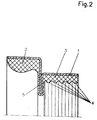
- Fig. 2 shows a plug with a radial projection of the connecting tube which faces inwards, the diameter of the connecting tube being widened again in the further course of the plug compared to the radial projection.
- Fig. 3 shows a plug-in piece, wherein the first and the second sealing ring are engaged at the ends facing away from one another by a radial projection of the connecting tube and the radial projection engages over the sealing ring 3 in the radial direction and is designed as an axial stop for one of the cylinder surfaces.
- Fig. 1 shows a plug, with a first radial projection 5 of the connecting tube 1, which arises from the fact that the diameter of the connecting tube 1 expanded by leaps and bounds.
- the two sealing rings 2 and 3 are connected to each other.
- the sealing ring is positively connected to the connecting tube.
- the elastomer is vulcanized onto the connecting pipe.
- the first sealing ring 2 points radially outwards and is delimited by a spherical periphery.
- the second sealing ring 3 points radially inwards and is fixed in the region of the enlarged diameter of the connecting pipe.
- first sealing ring 2 and the second sealing ring 3 are separated from one another by the first radial projection 5. This makes it possible to manufacture the two sealing rings from different elastomers.
- FIG. 2 shows a plug-in piece with an inward-pointing radial projection, the inside diameter of which is smaller than the inside diameter of the part of the connecting pipe 1 in front of and behind it in the axial direction.
- a plug-in piece designed in this way can be used, for example, to connect two cylinder surfaces which have an extremely different diameter exhibit, serve. The space between the two very different diameters of the cylinder surface need not be filled with elastomeric material.
- the plug-in piece is adapted to the different-sized diameters of the cylinder surfaces by the different-sized inner diameters of the plug-in surfaces lying on both sides in the axial direction from the radial projection. An elastomer is vulcanized to these in a thickness that meets the requirements.
- the plug shown here also has the advantage that both cylindrical surfaces are fixed by the radial projection with respect to their axial position to the plug.
- FIG. 3 shows a plug-in piece in which the first sealing ring 2 and the second sealing ring 3 are arranged in the same radial plane.
- the Ends facing away from each other engage the sealing rings by a radial projection 6 of the connecting tube 1.
- the radial projection overlapping the sealing ring 3 is designed as an axial stop for one of the cylinder surfaces.
Landscapes
- Engineering & Computer Science (AREA)
- General Engineering & Computer Science (AREA)
- Mechanical Engineering (AREA)
- Chemical & Material Sciences (AREA)
- Combustion & Propulsion (AREA)
- Gasket Seals (AREA)
- Quick-Acting Or Multi-Walled Pipe Joints (AREA)
Applications Claiming Priority (2)
| Application Number | Priority Date | Filing Date | Title |
|---|---|---|---|
| DE19548249 | 1995-12-22 | ||
| DE1995148249 DE19548249C2 (de) | 1995-12-22 | 1995-12-22 | Steckstück |
Publications (2)
| Publication Number | Publication Date |
|---|---|
| EP0780619A1 true EP0780619A1 (fr) | 1997-06-25 |
| EP0780619B1 EP0780619B1 (fr) | 2001-05-16 |
Family
ID=7781089
Family Applications (1)
| Application Number | Title | Priority Date | Filing Date |
|---|---|---|---|
| EP19960117923 Expired - Lifetime EP0780619B1 (fr) | 1995-12-22 | 1996-11-08 | Pièce enfichable |
Country Status (2)
| Country | Link |
|---|---|
| EP (1) | EP0780619B1 (fr) |
| DE (1) | DE19548249C2 (fr) |
Cited By (3)
| Publication number | Priority date | Publication date | Assignee | Title |
|---|---|---|---|---|
| DE19743183A1 (de) * | 1997-09-30 | 1999-04-22 | Uponor Anger Gmbh | Kombinationskupplung zur Bereitstellung von stufenlosen Winkellagen zwischen Rohren |
| EP2169292A1 (fr) * | 2008-09-30 | 2010-03-31 | Carl Freudenberg KG | Pièce enfichable |
| WO2020160888A1 (fr) * | 2019-02-06 | 2020-08-13 | Carl Freudenberg Kg | Élément enfichable et utilisation de l'élément enfichable |
Families Citing this family (11)
| Publication number | Priority date | Publication date | Assignee | Title |
|---|---|---|---|---|
| DE19902953B4 (de) * | 1999-01-26 | 2005-11-24 | Carl Freudenberg Kg | Steckstück |
| DE102005040394A1 (de) * | 2005-08-25 | 2007-03-01 | Josef Zimmermann | Steckmuffe |
| EP2027407B1 (fr) | 2006-06-14 | 2020-06-10 | Carl Freudenberg KG | Composants de joint de tube |
| DE102007053508A1 (de) | 2007-11-09 | 2009-01-29 | Daimler Ag | Anordnung mit zumindest zwei Hohlkörpern und einem die Hohlkörper verbindenden Steckstück sowie ein Verfahren zum Verbinden von zwei Hohlkörpern mit einem Steckstück |
| US20090267307A1 (en) | 2008-04-28 | 2009-10-29 | Freudenberg-Nok General Partnership | High Pressure Tube Seal |
| EP2385276A1 (fr) | 2010-05-03 | 2011-11-09 | Carl Freudenberg KG | Composants de scellage de tube |
| DE102012019106A1 (de) | 2012-09-28 | 2014-04-03 | Carl Freudenberg Kg | Steckstück |
| DE102012019105A1 (de) * | 2012-09-28 | 2014-04-03 | Carl Freudenberg Kg | Steckstück |
| JP6938243B2 (ja) * | 2017-06-26 | 2021-09-22 | Nok株式会社 | 配管接続構造 |
| US10788150B2 (en) | 2018-03-22 | 2020-09-29 | Freudenberg-Nok General Partnership | Tube seal |
| EP4726244A1 (fr) * | 2023-06-08 | 2026-04-15 | NOK Corporation | Outil de raccordement de tuyaux et procédé de raccordement de tuyaux l'utilisant |
Citations (6)
| Publication number | Priority date | Publication date | Assignee | Title |
|---|---|---|---|---|
| DE1576725A1 (de) * | 1967-05-18 | 1970-05-06 | Kloeckner Humboldt Deutz Ag | Wassergekuehlte Einzelzylinderkoepfe einer mehrzylindrigen Brennkraftmaschine |
| DE2143734A1 (de) * | 1971-09-01 | 1973-03-15 | Daimler Benz Ag | Brennkraftmaschine mit einem in den kuehlwasser-durchgang zwischen zylinderkopf und kurbelgehaeuse eingesetzten zwischenrohr |
| DE2344327B2 (de) * | 1972-09-15 | 1979-04-19 | Societe Nationale D'etude Et De Construction De Moteurs D'aviation S.N.E. C.M.A., Paris | Dichtungsanordnung für eine Rohrleitung |
| GB2055165A (en) * | 1979-01-25 | 1981-02-25 | Campbell J K | Telescopic pipe joints |
| DE3418718A1 (de) * | 1984-05-19 | 1985-11-21 | Klöckner-Humboldt-Deutz AG, 5000 Köln | Huelse mit aufvulkanisierten dichtlippen |
| US5106129A (en) * | 1990-10-09 | 1992-04-21 | Delaware Capital Formation, Inc. | Flexible coupling for transferring a fluid between two fluid conduits |
Family Cites Families (1)
| Publication number | Priority date | Publication date | Assignee | Title |
|---|---|---|---|---|
| DE7225929U (de) * | 1972-07-12 | 1972-11-09 | Grohe H Kg | Rohrverbindung fuer badewannenueberlauf |
-
1995
- 1995-12-22 DE DE1995148249 patent/DE19548249C2/de not_active Expired - Lifetime
-
1996
- 1996-11-08 EP EP19960117923 patent/EP0780619B1/fr not_active Expired - Lifetime
Patent Citations (7)
| Publication number | Priority date | Publication date | Assignee | Title |
|---|---|---|---|---|
| DE1576725A1 (de) * | 1967-05-18 | 1970-05-06 | Kloeckner Humboldt Deutz Ag | Wassergekuehlte Einzelzylinderkoepfe einer mehrzylindrigen Brennkraftmaschine |
| DE2143734A1 (de) * | 1971-09-01 | 1973-03-15 | Daimler Benz Ag | Brennkraftmaschine mit einem in den kuehlwasser-durchgang zwischen zylinderkopf und kurbelgehaeuse eingesetzten zwischenrohr |
| DE2344327B2 (de) * | 1972-09-15 | 1979-04-19 | Societe Nationale D'etude Et De Construction De Moteurs D'aviation S.N.E. C.M.A., Paris | Dichtungsanordnung für eine Rohrleitung |
| GB2055165A (en) * | 1979-01-25 | 1981-02-25 | Campbell J K | Telescopic pipe joints |
| DE3418718A1 (de) * | 1984-05-19 | 1985-11-21 | Klöckner-Humboldt-Deutz AG, 5000 Köln | Huelse mit aufvulkanisierten dichtlippen |
| DE3418718C2 (fr) | 1984-05-19 | 1992-09-03 | Kloeckner-Humboldt-Deutz Ag, 5000 Koeln, De | |
| US5106129A (en) * | 1990-10-09 | 1992-04-21 | Delaware Capital Formation, Inc. | Flexible coupling for transferring a fluid between two fluid conduits |
Cited By (4)
| Publication number | Priority date | Publication date | Assignee | Title |
|---|---|---|---|---|
| DE19743183A1 (de) * | 1997-09-30 | 1999-04-22 | Uponor Anger Gmbh | Kombinationskupplung zur Bereitstellung von stufenlosen Winkellagen zwischen Rohren |
| DE19743183B4 (de) * | 1997-09-30 | 2009-04-30 | Maincor Anger Gmbh | Kombinationskupplung zur Bereitstellung von stufenlosen Winkellagen zwischen Rohren |
| EP2169292A1 (fr) * | 2008-09-30 | 2010-03-31 | Carl Freudenberg KG | Pièce enfichable |
| WO2020160888A1 (fr) * | 2019-02-06 | 2020-08-13 | Carl Freudenberg Kg | Élément enfichable et utilisation de l'élément enfichable |
Also Published As
| Publication number | Publication date |
|---|---|
| DE19548249A1 (de) | 1997-06-26 |
| EP0780619B1 (fr) | 2001-05-16 |
| DE19548249C2 (de) | 1999-01-07 |
Similar Documents
| Publication | Publication Date | Title |
|---|---|---|
| DE69219562T2 (de) | Dichtungsvorrichtung | |
| EP0780619A1 (fr) | Pièce enfichable | |
| DE102016101795A1 (de) | Dichtungsanordnungen und damit in Zusammenhang stehende Verfahren | |
| DE3317061A1 (de) | Flanschverbindungsanordnung | |
| DE102012019105A1 (de) | Steckstück | |
| DE102012019106A1 (de) | Steckstück | |
| EP2638302A1 (fr) | Roulement étanche | |
| EP2009331B1 (fr) | Presse-étoupe | |
| DE102016208697A1 (de) | Rotationsdichtungsanordnung mit druckaktivierbarer Rotationsdichtung sowie Rotationsdichtung | |
| EP3728910B1 (fr) | Système d'étanchéité | |
| EP3492785B1 (fr) | Anneau d'étanchéité et dispositif d'étanchéité comprenant un tel anneau d'étanchéité | |
| EP2927541A1 (fr) | Élément d'étanchéité et construction d'un joint de conduite | |
| EP3862599B1 (fr) | Bague d'étanchéité à lamelles à géométrie de section transversale en forme de x | |
| EP3940281B1 (fr) | Manchon de tuyau | |
| DE3202381A1 (de) | "radial - wellendichtring" | |
| DE102016215154B4 (de) | Abdichtungssystem | |
| EP2077410B1 (fr) | Système de connexion pour systèmes de transport de fluide | |
| EP0128241B1 (fr) | Joint d'étanchéité | |
| DE102017122269A1 (de) | Dichtungsanordnung, insbesondere für Radialgelenklager | |
| DE102019110183A1 (de) | Gelenklager | |
| EP3534025B1 (fr) | Palier | |
| EP3728819B1 (fr) | Système d'étanchéité | |
| DE3540321C2 (fr) | ||
| EP4058680B1 (fr) | Unité de roulement de roue | |
| DE19949864C1 (de) | Dichtring für eine Steckmuffenverbindung zweier Rohre |
Legal Events
| Date | Code | Title | Description |
|---|---|---|---|
| PUAI | Public reference made under article 153(3) epc to a published international application that has entered the european phase |
Free format text: ORIGINAL CODE: 0009012 |
|
| 17P | Request for examination filed |
Effective date: 19970414 |
|
| AK | Designated contracting states |
Kind code of ref document: A1 Designated state(s): BE FR GB IT SE |
|
| 17Q | First examination report despatched |
Effective date: 19990820 |
|
| GRAG | Despatch of communication of intention to grant |
Free format text: ORIGINAL CODE: EPIDOS AGRA |
|
| GRAG | Despatch of communication of intention to grant |
Free format text: ORIGINAL CODE: EPIDOS AGRA |
|
| GRAH | Despatch of communication of intention to grant a patent |
Free format text: ORIGINAL CODE: EPIDOS IGRA |
|
| GRAH | Despatch of communication of intention to grant a patent |
Free format text: ORIGINAL CODE: EPIDOS IGRA |
|
| GRAA | (expected) grant |
Free format text: ORIGINAL CODE: 0009210 |
|
| AK | Designated contracting states |
Kind code of ref document: B1 Designated state(s): BE FR GB IT SE |
|
| ITF | It: translation for a ep patent filed | ||
| GBT | Gb: translation of ep patent filed (gb section 77(6)(a)/1977) |
Effective date: 20010731 |
|
| ET | Fr: translation filed | ||
| REG | Reference to a national code |
Ref country code: GB Ref legal event code: IF02 |
|
| RAP2 | Party data changed (patent owner data changed or rights of a patent transferred) |
Owner name: CARL FREUDENBERG KG |
|
| PLBE | No opposition filed within time limit |
Free format text: ORIGINAL CODE: 0009261 |
|
| STAA | Information on the status of an ep patent application or granted ep patent |
Free format text: STATUS: NO OPPOSITION FILED WITHIN TIME LIMIT |
|
| 26N | No opposition filed | ||
| REG | Reference to a national code |
Ref country code: FR Ref legal event code: PLFP Year of fee payment: 20 |
|
| PGFP | Annual fee paid to national office [announced via postgrant information from national office to epo] |
Ref country code: GB Payment date: 20151123 Year of fee payment: 20 |
|
| PGFP | Annual fee paid to national office [announced via postgrant information from national office to epo] |
Ref country code: SE Payment date: 20151120 Year of fee payment: 20 Ref country code: FR Payment date: 20151123 Year of fee payment: 20 Ref country code: BE Payment date: 20151126 Year of fee payment: 20 |
|
| PGFP | Annual fee paid to national office [announced via postgrant information from national office to epo] |
Ref country code: IT Payment date: 20151130 Year of fee payment: 20 |
|
| REG | Reference to a national code |
Ref country code: GB Ref legal event code: PE20 Expiry date: 20161107 |
|
| PG25 | Lapsed in a contracting state [announced via postgrant information from national office to epo] |
Ref country code: GB Free format text: LAPSE BECAUSE OF EXPIRATION OF PROTECTION Effective date: 20161107 |