EP0780633A2 - Dispositif pour la combustion d'impuretés dans un courant de milieu - Google Patents
Dispositif pour la combustion d'impuretés dans un courant de milieu Download PDFInfo
- Publication number
- EP0780633A2 EP0780633A2 EP96118667A EP96118667A EP0780633A2 EP 0780633 A2 EP0780633 A2 EP 0780633A2 EP 96118667 A EP96118667 A EP 96118667A EP 96118667 A EP96118667 A EP 96118667A EP 0780633 A2 EP0780633 A2 EP 0780633A2
- Authority
- EP
- European Patent Office
- Prior art keywords
- section
- cross
- housing
- housing section
- outlet
- Prior art date
- Legal status (The legal status is an assumption and is not a legal conclusion. Google has not performed a legal analysis and makes no representation as to the accuracy of the status listed.)
- Granted
Links
- 239000012535 impurity Substances 0.000 title claims 2
- 239000003054 catalyst Substances 0.000 claims description 8
- 230000007704 transition Effects 0.000 claims description 2
- 230000003197 catalytic effect Effects 0.000 abstract description 3
- 239000000356 contaminant Substances 0.000 description 8
- 238000002485 combustion reaction Methods 0.000 description 4
- 239000000446 fuel Substances 0.000 description 3
- 238000000429 assembly Methods 0.000 description 1
- 230000000712 assembly Effects 0.000 description 1
- 230000000694 effects Effects 0.000 description 1
- 238000002474 experimental method Methods 0.000 description 1
- 230000010354 integration Effects 0.000 description 1
- 238000012423 maintenance Methods 0.000 description 1
- 239000002184 metal Substances 0.000 description 1
- 238000007669 thermal treatment Methods 0.000 description 1
Images

Classifications
-
- F—MECHANICAL ENGINEERING; LIGHTING; HEATING; WEAPONS; BLASTING
- F23—COMBUSTION APPARATUS; COMBUSTION PROCESSES
- F23G—CREMATION FURNACES; CONSUMING WASTE PRODUCTS BY COMBUSTION
- F23G7/00—Incinerators or other apparatus for consuming industrial waste, e.g. chemicals
- F23G7/06—Incinerators or other apparatus for consuming industrial waste, e.g. chemicals of waste gases or noxious gases, e.g. exhaust gases
- F23G7/07—Incinerators or other apparatus for consuming industrial waste, e.g. chemicals of waste gases or noxious gases, e.g. exhaust gases in which combustion takes place in the presence of catalytic material
-
- F—MECHANICAL ENGINEERING; LIGHTING; HEATING; WEAPONS; BLASTING
- F23—COMBUSTION APPARATUS; COMBUSTION PROCESSES
- F23G—CREMATION FURNACES; CONSUMING WASTE PRODUCTS BY COMBUSTION
- F23G7/00—Incinerators or other apparatus for consuming industrial waste, e.g. chemicals
- F23G7/06—Incinerators or other apparatus for consuming industrial waste, e.g. chemicals of waste gases or noxious gases, e.g. exhaust gases
- F23G7/061—Incinerators or other apparatus for consuming industrial waste, e.g. chemicals of waste gases or noxious gases, e.g. exhaust gases with supplementary heating
- F23G7/065—Incinerators or other apparatus for consuming industrial waste, e.g. chemicals of waste gases or noxious gases, e.g. exhaust gases with supplementary heating using gaseous or liquid fuel
- F23G7/066—Incinerators or other apparatus for consuming industrial waste, e.g. chemicals of waste gases or noxious gases, e.g. exhaust gases with supplementary heating using gaseous or liquid fuel preheating the waste gas by the heat of the combustion, e.g. recuperation type incinerator
Definitions
- the invention relates to a device for burning contaminants contained in a media stream consisting of a housing with an inlet connector and an outlet connector, a heat exchanger and a burner device, which is formed from individual burners arranged distributed over the cross section of the media stream.
- the housing consists of a cylindrical container, the media stream being passed via an inlet connection through axially aligned heat exchanger tubes arranged in the container, through an annular chamber equipped with a burner device and via a coaxial in the container stored high-speed pipe after the flow around the heat exchanger pipes is fed to the outlet port.
- the cylindrical container is composed of at least three coaxially successive container sections.
- the first container section contains the heat exchanger tubes extending over its length
- the second container section is equipped with the burner device consisting of individual burners.
- the third container section comprises the coaxially arranged high speed tube. With an end piece, this penetrates the burner device in the second container section and extends to the first container section.
- the invention has for its object to provide a device of the type described in such a way that when using a commercially available heat exchanger with a rectangular cross-section, the media stream loaded with contaminants is aerodynamically optimal from the heat exchanger into the combustion chamber and the media stream freed from contaminants is also aerodynamically optimal from there can be removed via the heat exchanger.
- the aligned arrangement of the inlet and outlet cross-section of the inlet or outlet connector creates the prerequisite for arranging a commercially available heat exchanger outside the housing, which, like the heat exchanger, is cuboid-shaped, directly on the connector.
- the heat exchanger thus represents a structural unit which is compactly connected to the housing and, like the first container section of the known device, can be easily removed and removed for maintenance and repair purposes.
- the ability to dismantle the housing is also ensured in the same way by dividing it into housing sections.
- a second housing section, equipped with the outlet connection is connected to a first housing section equipped with the inlet connection piece, which receives the burner device, via which the media stream freed of contaminants is discharged via the heat exchanger.
- the media flow thus has a rectangular flow cross-section, the individual burners of the burner device being arranged distributed over the cross-section of the first housing section.
- the flow conditions of the media flow are therefore ideally solved in the device according to the invention using an inexpensive heat exchanger as in the device known from DE 44 14 875 C1, which requires complex ring-shaped heat exchanger tube bundles inside the housing due to a coaxial passage of the media flow.
- the burner device is followed by a catalyst device extending over its cross section in the flow direction of the media stream.
- honeycomb-shaped catalyst device is favored by the fact that there is a rectangular flow cross section and the mean flow rate in the burner device can be reduced considerably by the individual burners.
- the individual burners which are operated in a manner known per se with a swirl superimposition, make it possible to reduce the average speed of the media flow at the treatment temperature to approximately 5 m / s.
- the length of the section of the first housing section immediately following the burner device depends on the residence time of the media flow, which is necessary to ensure complete combustion of the contaminants. Due to the reduced speed of the media flow in connection with the more intensive effect of the individual burners, the overall length of the housing can also be considerably shortened with an additionally integrated catalytic converter.
- honeycomb-shaped or bulk catalysts with a uniform temperature distribution across the cross-section can be arranged at a distance of 8 - 150 cm after the individual burners without being damaged by their heat.
- the housing can be made particularly compact if the first housing section and the second housing section each have a rectangular cross section and a common longitudinal wall.
- a compensator that compensates for different thermal expansions is arranged between the inlet connector and / or the outlet connector and the first or second housing section.
- a further embodiment of the invention provides to provide a guide device that compares the media flow in a transition area from the first housing section to the second housing section.
- the guide device preferably consists of lamellae which are arcuate in cross section or a perforated plate, the free perforated area of which is between 20% and 40% of the cross section of the first housing section.
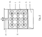
- the device comprises a cuboid housing 1 and a schematically illustrated, also cuboidal heat exchanger 2, which is designed as a conventional counterflow plate heat exchanger.
- the housing 1 is divided into a first housing section 3 and a second housing section 4, the two housing sections 3 and 4 having a common longitudinal wall 5 which extends essentially over their length and are connected to one another via perforations of a perforated plate 6, which in the direction of flow of a media stream End of a housing section 3 and the beginning of the housing section 4 defined.
- an inlet connector 7 and at the end of the housing section 4, an outlet connector 8 is provided.
- a compensator 10 is interposed between an outlet cross section of the housing section 4 and an inlet cross section of the outlet connector 8 for the purpose of compensating for expansion between the two housing sections 3 and 4 and the inlet and outlet connectors 7 and 8.
- the cuboidal heat exchanger 2 can be connected compactly to the housing 1.
- Individual burners 11, which form a burner device, are arranged in the housing section 3 distributed over its cross section.
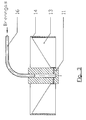
- the individual burners 11 are held in a rectangular plate 12 adapted to the cross section of the housing section 3 and, as shown in FIG. 3, comprise connecting pieces 14 equipped with metal blades 13 which sit in the plate 12.
- the media flow reaches the flame area of the individual burners 11 via the connecting pieces 14 with intensive swirling.
- gas-permeable - e.g., extending over the cross section of the housing section 3 - honeycomb-shaped catalysts 17 are arranged, so that the device allows a catalytic treatment in addition to a thermal treatment of a media stream loaded with contaminants.
Landscapes
- Engineering & Computer Science (AREA)
- Environmental & Geological Engineering (AREA)
- Mechanical Engineering (AREA)
- General Engineering & Computer Science (AREA)
- Chemical & Material Sciences (AREA)
- Chemical Kinetics & Catalysis (AREA)
- Hydrogen, Water And Hydrids (AREA)
- Combustion Of Fluid Fuel (AREA)
- Apparatus For Radiation Diagnosis (AREA)
- Gasification And Melting Of Waste (AREA)
Applications Claiming Priority (2)
| Application Number | Priority Date | Filing Date | Title |
|---|---|---|---|
| DE19547688 | 1995-12-20 | ||
| DE19547688A DE19547688C1 (de) | 1995-12-20 | 1995-12-20 | Vorrichtung zum Verbrennen von in einem Medienstrom enthaltenen Störstoffen |
Publications (3)
| Publication Number | Publication Date |
|---|---|
| EP0780633A2 true EP0780633A2 (fr) | 1997-06-25 |
| EP0780633A3 EP0780633A3 (fr) | 1999-01-27 |
| EP0780633B1 EP0780633B1 (fr) | 2002-10-23 |
Family
ID=7780732
Family Applications (1)
| Application Number | Title | Priority Date | Filing Date |
|---|---|---|---|
| EP96118667A Expired - Lifetime EP0780633B1 (fr) | 1995-12-20 | 1996-11-21 | Dispositif pour la combustion d'impuretés dans un courant de milieu |
Country Status (3)
| Country | Link |
|---|---|
| EP (1) | EP0780633B1 (fr) |
| AT (1) | ATE226705T1 (fr) |
| DE (2) | DE19547688C1 (fr) |
Citations (1)
| Publication number | Priority date | Publication date | Assignee | Title |
|---|---|---|---|---|
| DE4414875C1 (de) | 1994-04-28 | 1995-08-31 | Krantz Tkt Gmbh | Vorrichtung zum Verbrennen von in einem Medienstrom enthaltenen Störstoffen |
Family Cites Families (7)
| Publication number | Priority date | Publication date | Assignee | Title |
|---|---|---|---|---|
| US3881874A (en) * | 1973-05-07 | 1975-05-06 | Pyronics Inc | Thermal incineration air pollution control device |
| US4544526A (en) * | 1982-05-03 | 1985-10-01 | Durr Industries, Inc. | Oven heat exchanger |
| DD207567A1 (de) * | 1982-05-06 | 1984-03-07 | Fuerstenwalde Chem Tankanlagen | Vorrichtung zur katalytischen verbrennung unerwuenschter abluft-bzw. abgasbestandteile |
| GB2178839B (en) * | 1985-08-06 | 1989-08-16 | British Petroleum Co Plc | Combustor |
| DE59100409D1 (de) * | 1990-01-30 | 1993-11-04 | Ltg Lufttechnische Gmbh | Regenerativ-reaktor zum verbrennen von industriellen abgasen. |
| DE4014415C2 (de) * | 1990-05-04 | 1993-12-09 | Gea Luftkuehler Happel Gmbh | Vorrichtung zur katalytischen Oxidation der schädlichen Bestandteile in einem abgekühlten Trägergas eines verfahrenstechnischen Prozesses |
| DE29609686U1 (de) * | 1996-05-31 | 1996-08-14 | H. Krantz-Tkt Gmbh, 51465 Bergisch Gladbach | Einrichtung zum Verbrennen von Schadstoffen |
-
1995
- 1995-12-20 DE DE19547688A patent/DE19547688C1/de not_active Expired - Fee Related
-
1996
- 1996-11-21 DE DE59609818T patent/DE59609818D1/de not_active Expired - Fee Related
- 1996-11-21 EP EP96118667A patent/EP0780633B1/fr not_active Expired - Lifetime
- 1996-11-21 AT AT96118667T patent/ATE226705T1/de not_active IP Right Cessation
Patent Citations (1)
| Publication number | Priority date | Publication date | Assignee | Title |
|---|---|---|---|---|
| DE4414875C1 (de) | 1994-04-28 | 1995-08-31 | Krantz Tkt Gmbh | Vorrichtung zum Verbrennen von in einem Medienstrom enthaltenen Störstoffen |
Also Published As
| Publication number | Publication date |
|---|---|
| DE59609818D1 (de) | 2002-11-28 |
| DE19547688C1 (de) | 1997-08-14 |
| EP0780633B1 (fr) | 2002-10-23 |
| ATE226705T1 (de) | 2002-11-15 |
| EP0780633A3 (fr) | 1999-01-27 |
Similar Documents
| Publication | Publication Date | Title |
|---|---|---|
| EP0125572B1 (fr) | Brûleur polycombustible | |
| DE69305747T2 (de) | Vorrichtung zum mischen von zwei flüssigkeiten unterschiedlicher temperatur | |
| EP0438682B1 (fr) | Système d'échappement avec filtre à particules et brûleur de régénération | |
| EP2796195A1 (fr) | Réacteur tubulaire continu | |
| DE2433217A1 (de) | Einrichtung zur zufuhr von hochtemperaturmaterial | |
| DE102021111759A1 (de) | Abgasbehandlungsmodul | |
| EP0616022B1 (fr) | Procédé pour la gazéification sous pression de combustibles finement divisés | |
| DE19755126B4 (de) | Katalysatoranordnung mit zweisträngiger Abgasführung | |
| EP0686250B1 (fr) | Dispositif et procede permettant de bruler des constituants oxydables dans un gaz porteur a epurer | |
| EP0972560B1 (fr) | Procédé et dispositif pour le mélange intensif de réactants | |
| EP0352342B1 (fr) | Brûleur pour des procédés de séchage ou de purification de gaz | |
| DE2907694A1 (de) | Mischvorrichtung fuer stroemende fluessige, gas- oder dampffoermige medien | |
| EP0780633B1 (fr) | Dispositif pour la combustion d'impuretés dans un courant de milieu | |
| DE3538515C2 (fr) | ||
| DE69204083T2 (de) | Verfahren zur Verhinderung von Ablagerungen stromabwärts eines Mischers und Vorrichtung zur Durchführung des Verfahrens. | |
| DE2822582C3 (de) | Kühlmittelleit- und Walzgutführungseinrichtung für die intermittierende Kühlung von Walzgut, insbesondere von Draht, Feineisen o.dgl. | |
| EP0451662B1 (fr) | Brûleur récupérateur | |
| EP3366789B1 (fr) | Unité d'alimentation en liquide de refroidissement pour une hotte aspirante de convertisseur | |
| WO1990012987A1 (fr) | Dispositif d'amenee de combustibles et d'additifs a des installations de combustion | |
| DE2910370C2 (de) | Auspuffanlage für Brennkraftmaschinen mit zwei parallel angeordneten Abgassträngen | |
| DE1751059C3 (de) | Mit einem Schalldämpfer vereinigte Abgaskuhlanlage für Brennkraftmaschinen | |
| DE3410143A1 (de) | Vorrichtung zum entstauben von unter druck stehendem gas | |
| DE19537112C2 (de) | Begasungseinrichtung | |
| EP0679840A2 (fr) | Dispositif pour la combustion d'impuretés | |
| DE10341644B4 (de) | Wendelförmiger Wärmeaustauscher |
Legal Events
| Date | Code | Title | Description |
|---|---|---|---|
| PUAI | Public reference made under article 153(3) epc to a published international application that has entered the european phase |
Free format text: ORIGINAL CODE: 0009012 |
|
| AK | Designated contracting states |
Kind code of ref document: A2 Designated state(s): AT CH DE FR GB IT LI SE |
|
| PUAL | Search report despatched |
Free format text: ORIGINAL CODE: 0009013 |
|
| AK | Designated contracting states |
Kind code of ref document: A3 Designated state(s): AT CH DE FR GB IT LI SE |
|
| 17P | Request for examination filed |
Effective date: 19990115 |
|
| GRAG | Despatch of communication of intention to grant |
Free format text: ORIGINAL CODE: EPIDOS AGRA |
|
| GRAG | Despatch of communication of intention to grant |
Free format text: ORIGINAL CODE: EPIDOS AGRA |
|
| GRAH | Despatch of communication of intention to grant a patent |
Free format text: ORIGINAL CODE: EPIDOS IGRA |
|
| 17Q | First examination report despatched |
Effective date: 20020423 |
|
| GRAH | Despatch of communication of intention to grant a patent |
Free format text: ORIGINAL CODE: EPIDOS IGRA |
|
| GRAA | (expected) grant |
Free format text: ORIGINAL CODE: 0009210 |
|
| AK | Designated contracting states |
Kind code of ref document: B1 Designated state(s): AT CH DE FR GB IT LI SE |
|
| PG25 | Lapsed in a contracting state [announced via postgrant information from national office to epo] |
Ref country code: IT Free format text: LAPSE BECAUSE OF FAILURE TO SUBMIT A TRANSLATION OF THE DESCRIPTION OR TO PAY THE FEE WITHIN THE PRE;WARNING: LAPSES OF ITALIAN PATENTS WITH EFFECTIVE DATE BEFORE 2007 MAY HAVE OCCURRED AT ANY TIME BEFORE 2007. THE CORRECT EFFECTIVE DATE MAY BE DIFFERENT FROM THE ONE RECORDED.SCRIBED TIME-LIMIT Effective date: 20021023 Ref country code: GB Free format text: LAPSE BECAUSE OF FAILURE TO SUBMIT A TRANSLATION OF THE DESCRIPTION OR TO PAY THE FEE WITHIN THE PRESCRIBED TIME-LIMIT Effective date: 20021023 Ref country code: FR Free format text: LAPSE BECAUSE OF FAILURE TO SUBMIT A TRANSLATION OF THE DESCRIPTION OR TO PAY THE FEE WITHIN THE PRESCRIBED TIME-LIMIT Effective date: 20021023 |
|
| REF | Corresponds to: |
Ref document number: 226705 Country of ref document: AT Date of ref document: 20021115 Kind code of ref document: T |
|
| REG | Reference to a national code |
Ref country code: GB Ref legal event code: FG4D Free format text: NOT ENGLISH |
|
| REG | Reference to a national code |
Ref country code: CH Ref legal event code: EP |
|
| PG25 | Lapsed in a contracting state [announced via postgrant information from national office to epo] |
Ref country code: AT Free format text: LAPSE BECAUSE OF NON-PAYMENT OF DUE FEES Effective date: 20021121 |
|
| REF | Corresponds to: |
Ref document number: 59609818 Country of ref document: DE Date of ref document: 20021128 |
|
| PG25 | Lapsed in a contracting state [announced via postgrant information from national office to epo] |
Ref country code: LI Free format text: LAPSE BECAUSE OF NON-PAYMENT OF DUE FEES Effective date: 20021130 Ref country code: CH Free format text: LAPSE BECAUSE OF NON-PAYMENT OF DUE FEES Effective date: 20021130 |
|
| PG25 | Lapsed in a contracting state [announced via postgrant information from national office to epo] |
Ref country code: SE Free format text: LAPSE BECAUSE OF FAILURE TO SUBMIT A TRANSLATION OF THE DESCRIPTION OR TO PAY THE FEE WITHIN THE PRESCRIBED TIME-LIMIT Effective date: 20030123 |
|
| GBV | Gb: ep patent (uk) treated as always having been void in accordance with gb section 77(7)/1977 [no translation filed] |
Effective date: 20021023 |
|
| PG25 | Lapsed in a contracting state [announced via postgrant information from national office to epo] |
Ref country code: DE Free format text: LAPSE BECAUSE OF NON-PAYMENT OF DUE FEES Effective date: 20030603 |
|
| REG | Reference to a national code |
Ref country code: CH Ref legal event code: PL |
|
| EN | Fr: translation not filed | ||
| PLBE | No opposition filed within time limit |
Free format text: ORIGINAL CODE: 0009261 |
|
| STAA | Information on the status of an ep patent application or granted ep patent |
Free format text: STATUS: NO OPPOSITION FILED WITHIN TIME LIMIT |
|
| 26N | No opposition filed |
Effective date: 20030724 |