EP0780925B1 - Dispositif de blindage de plusieurs câbles contre les perturbations électromagnétiques - Google Patents
Dispositif de blindage de plusieurs câbles contre les perturbations électromagnétiques Download PDFInfo
- Publication number
- EP0780925B1 EP0780925B1 EP96120251A EP96120251A EP0780925B1 EP 0780925 B1 EP0780925 B1 EP 0780925B1 EP 96120251 A EP96120251 A EP 96120251A EP 96120251 A EP96120251 A EP 96120251A EP 0780925 B1 EP0780925 B1 EP 0780925B1
- Authority
- EP
- European Patent Office
- Prior art keywords
- metallic
- cables
- holes
- cubicle
- perforated
- Prior art date
- Legal status (The legal status is an assumption and is not a legal conclusion. Google has not performed a legal analysis and makes no representation as to the accuracy of the status listed.)
- Expired - Lifetime
Links
- 229920001971 elastomer Polymers 0.000 claims description 35
- 239000000806 elastomer Substances 0.000 claims description 35
- 230000006835 compression Effects 0.000 claims description 16
- 238000007906 compression Methods 0.000 claims description 16
- 239000004020 conductor Substances 0.000 claims description 5
- 125000006850 spacer group Chemical group 0.000 claims description 4
- 239000002184 metal Substances 0.000 claims description 2
- 239000000463 material Substances 0.000 description 10
- 239000006260 foam Substances 0.000 description 3
- 230000000903 blocking effect Effects 0.000 description 2
- 238000010276 construction Methods 0.000 description 2
- 230000008878 coupling Effects 0.000 description 1
- 238000010168 coupling process Methods 0.000 description 1
- 238000005859 coupling reaction Methods 0.000 description 1
- 230000001939 inductive effect Effects 0.000 description 1
- 230000037431 insertion Effects 0.000 description 1
- 238000003780 insertion Methods 0.000 description 1
- 238000004519 manufacturing process Methods 0.000 description 1
- 239000002245 particle Substances 0.000 description 1
Images


Classifications
-
- H—ELECTRICITY
- H05—ELECTRIC TECHNIQUES NOT OTHERWISE PROVIDED FOR
- H05K—PRINTED CIRCUITS; CASINGS OR CONSTRUCTIONAL DETAILS OF ELECTRIC APPARATUS; MANUFACTURE OF ASSEMBLAGES OF ELECTRICAL COMPONENTS
- H05K9/00—Screening of apparatus or components against electric or magnetic fields
- H05K9/0007—Casings
- H05K9/0018—Casings with provisions to reduce aperture leakages in walls, e.g. terminals, connectors, cables
-
- H—ELECTRICITY
- H01—ELECTRIC ELEMENTS
- H01R—ELECTRICALLY-CONDUCTIVE CONNECTIONS; STRUCTURAL ASSOCIATIONS OF A PLURALITY OF MUTUALLY-INSULATED ELECTRICAL CONNECTING ELEMENTS; COUPLING DEVICES; CURRENT COLLECTORS
- H01R13/00—Details of coupling devices of the kinds covered by groups H01R12/70 or H01R24/00 - H01R33/00
- H01R13/648—Protective earth or shield arrangements on coupling devices, e.g. anti-static shielding
- H01R13/658—High frequency shielding arrangements, e.g. against EMI [Electro-Magnetic Interference] or EMP [Electro-Magnetic Pulse]
- H01R13/6581—Shield structure
- H01R13/6582—Shield structure with resilient means for engaging mating connector
- H01R13/6583—Shield structure with resilient means for engaging mating connector with separate conductive resilient members between mating shield members
-
- H—ELECTRICITY
- H01—ELECTRIC ELEMENTS
- H01R—ELECTRICALLY-CONDUCTIVE CONNECTIONS; STRUCTURAL ASSOCIATIONS OF A PLURALITY OF MUTUALLY-INSULATED ELECTRICAL CONNECTING ELEMENTS; COUPLING DEVICES; CURRENT COLLECTORS
- H01R13/00—Details of coupling devices of the kinds covered by groups H01R12/70 or H01R24/00 - H01R33/00
- H01R13/648—Protective earth or shield arrangements on coupling devices, e.g. anti-static shielding
- H01R13/658—High frequency shielding arrangements, e.g. against EMI [Electro-Magnetic Interference] or EMP [Electro-Magnetic Pulse]
- H01R13/6581—Shield structure
- H01R13/6585—Shielding material individually surrounding or interposed between mutually spaced contacts
- H01R13/6588—Shielding material individually surrounding or interposed between mutually spaced contacts with through openings for individual contacts
-
- H—ELECTRICITY
- H01—ELECTRIC ELEMENTS
- H01R—ELECTRICALLY-CONDUCTIVE CONNECTIONS; STRUCTURAL ASSOCIATIONS OF A PLURALITY OF MUTUALLY-INSULATED ELECTRICAL CONNECTING ELEMENTS; COUPLING DEVICES; CURRENT COLLECTORS
- H01R13/00—Details of coupling devices of the kinds covered by groups H01R12/70 or H01R24/00 - H01R33/00
- H01R13/648—Protective earth or shield arrangements on coupling devices, e.g. anti-static shielding
- H01R13/658—High frequency shielding arrangements, e.g. against EMI [Electro-Magnetic Interference] or EMP [Electro-Magnetic Pulse]
- H01R13/6591—Specific features or arrangements of connection of shield to conductive members
- H01R13/6592—Specific features or arrangements of connection of shield to conductive members the conductive member being a shielded cable
- H01R13/6593—Specific features or arrangements of connection of shield to conductive members the conductive member being a shielded cable the shield being composed of different pieces
-
- H—ELECTRICITY
- H01—ELECTRIC ELEMENTS
- H01R—ELECTRICALLY-CONDUCTIVE CONNECTIONS; STRUCTURAL ASSOCIATIONS OF A PLURALITY OF MUTUALLY-INSULATED ELECTRICAL CONNECTING ELEMENTS; COUPLING DEVICES; CURRENT COLLECTORS
- H01R9/00—Structural associations of a plurality of mutually-insulated electrical connecting elements, e.g. terminal strips or terminal blocks; Terminals or binding posts mounted upon a base or in a case; Bases therefor
- H01R9/03—Connectors arranged to contact a plurality of the conductors of a multiconductor cable, e.g. tapping connections
- H01R9/05—Connectors arranged to contact a plurality of the conductors of a multiconductor cable, e.g. tapping connections for coaxial cables
- H01R9/0527—Connection to outer conductor by action of a resilient member, e.g. spring
Definitions
- the present invention relates to a device to establish an electric contact between the metallic shielding braid of a cable and the metallic mass of a cubicle inside of which electronic or telecommunication equipment is housed in the point where the cable passes through the wall of the cubicle.
- the portion of the shielded cable contained inside the cubicle may constitute an access way for electromagnetic disturbances due to currents circulating in the metallic shielding braid of the cable. Therefore it is important to guarantee an efficient drainage towards the mass of these currents induced in the point in which the cable penetrates inside the shielded space of the cubicle.
- the actually known devices are based on the use of special clamps in which one or more jaws to be moved along a shifting direction substantially orthogonal to the axis of the shielded cables tighten a plurality of shielded cables from which previously the isolating sheath has been locally removed uncovering the respective metallic shielding braid. Commonly several shielded cables are tightened together forcing the mobile jaw of the clamp in this way to assure through the metallic structure of the clamp the electric continuity with the metallic wall of the cubicle adjacent to the opening for the passage of the cables.
- the common architecture of these devices is the use of a clamp with orthogonal working compared to the axis of the shielded cables.
- the main object of the present invention is to overcome in an efficient way the difficulties and drawbacks of the known systems.
- the device according to the invention may be realized by a limited number of parts. It comprises essentially a perforated body made of conductive elastomer, such as a spongy foam of conductive elastomer material or also a non foamed conductive elastomer material provided with a plurality of parallel holes with a diameter suitable for the passage of a shielded cable (after having locally unwrapped its external isolating sheath).
- conductive elastomer such as a spongy foam of conductive elastomer material or also a non foamed conductive elastomer material provided with a plurality of parallel holes with a diameter suitable for the passage of a shielded cable (after having locally unwrapped its external isolating sheath).
- a metallic perforated panel or board which may be mechanically or electrically connected in a direct way to the metallic wall of the cubicle so that it recovers completely the opening made through the wall for the passage of the cables, is provided with holes which are essentially coaxial to the holes of the elastomer body which lies with one face directly on one plane face of the perforated metallic board.
- the device is completed by at least one compression counterboard, which is also provided with hole essentially coaxial to the holes of the metallic board and of the elastomer body which acts against the opposed face of the elastomer body.
- the assemblage is carried out by inserting freely the cables through the (coaxial) holes of the metallic board or panel already fixed or to be fixed directly on the wall of the cubicle, of the conductive elastomer body and of the compression counterboard.
- the compression means may be simple threaded tie rods passing through tubular spacers which define a correct limit of compression of the perforated elastomer body between both boards.
- the contact surface between the perforated elastomer body and the perforated metallic board which are electrically connected to the metallic wall of the cubicle represents a contact area distributed on the total opening for the passage of the cables or immediately adjacent to each hole for the passage of the respective cables in order to guarantee electric drainage courses with low resistivity for all cables , independently from their relative position compared to the dimensions of the passage opening or of the opening made through the metallic wall of the shielding cubicle.
- the device according to the invention assures a great uniformity and a low resistance of the drainage current courses for all shielded cables passing through the wall.
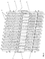
- this shows in a fragmentary way a rectangular opening 2 set up in the metallic wall 1 of a metallic shielding cubicle for the passage of shielded cables which have to abut inside of the shielded space of the cubicle.
- the opening 2 made through the wall 1 of the cubicle is completely covered by a perforated metallic panel or board 3.
- the board 3 has been previously provided with an alignment of holes 4 with a diameter which is sufficient for the passage of shielded cables.
- the metallic panel or board 3 may possibly be fixed mechanically and in close electric contact to the metallic wall 1 of the cubicle through a plurality of self-threading screws or bolts passing through holes 5 distributed along the coupling perimeter between the board 3 and the wall 1.
- a block or parallelepipedon 6 may be cut to measure from a piece of conductive elastomer, for example a spongy foam of an elastomer material charged with conductive fibres or particles in order to assure a certain electric conductivity to the mass of elastomer and provided with parallel preferably grooved holes 7 orderly disposed and which turn out to be essentially coaxial to the holes 4 of the metallic board 3.
- a piece of conductive elastomer for example a spongy foam of an elastomer material charged with conductive fibres or particles in order to assure a certain electric conductivity to the mass of elastomer and provided with parallel preferably grooved holes 7 orderly disposed and which turn out to be essentially coaxial to the holes 4 of the metallic board 3.
- the material or carpet from which the parallelepiped block 6 is obtained may be advantageously provided with a second row of holes 8 through the centre line plane where the material may be cut out in function of the required measures.
- a counterboard 9 is provided with a perforation 10 in a coordinate way analogous to the perforation 4 of the metallic board 3. Also in this case the holes 10 of the counterboard 9 turn out to be coaxial to the respective grooved holes 7 of the elastomer block 6 and of the holes 4 of the metallic board 3.
- Four tie rods 11 make it possible to compress the whole like a sandwich.
- Fig. 2 shows the phase of assemblage of the device which comprises the insertion of the cables 12 sequentially through one and the other of the perforated boards 9 and 3 and through the corresponding grooved holes 7 of the elastomer body 6, obviously unwrapping before the isolating sheath of the cables on the length passing through the grooved holes 7 of the conductive elastomer body 6.
- the elastomer material of the perforated parallelepiped block 6 is compressed causing a certain degree of deformation which makes the material clenching on the metallic shielding braid 13 of the cables passing through grooved holes 7.
- the conductive elastomer block 6 is compressed against the perforated metallic board 3 creating in this way a good electric contact uniformly distributed on the entire support surface and substantially in proximity of the contact area of the elastomer material with the shielding braid of each cable.
- the perforated metallic board 3 which is electrically connected to the metallic wall of the cubicle acts like a collector of possible induced currents on the shielding braid of the different passing cables which are in this way efficiently drained towards the metallic mass of the cubicle 1.
- perforated compression counterboard 9 may also be of metal and contribute through the tie rods to further reduce the resistance of the drainage courses towards the mass of the induced currents on the external shielding conductors of the cables.
- carpets of perforated elastomer material with different dimensional characteristics and in particular with different diameters of the holes for the passage of the cables and/or provided with conical shaped holes, and an analogous inventory of perforated boards make it possible to realize devices of different dimensions and quantities of cables, simplifying the storage problems and contributing also for the reduction of manufacturing costs of the parts setting up the device.
Landscapes
- Engineering & Computer Science (AREA)
- Microelectronics & Electronic Packaging (AREA)
- Shielding Devices Or Components To Electric Or Magnetic Fields (AREA)
- Installation Of Indoor Wiring (AREA)
- Insulated Conductors (AREA)
- Insertion, Bundling And Securing Of Wires For Electric Apparatuses (AREA)
- Details Of Indoor Wiring (AREA)
Claims (6)
- Dispositif de blindage convenant pour empêcher des perturbations du type électromagnétique pour des câbles blindés aboutissant sur un équipement électrique et de télécommunication logé à l'intérieur d'une armoire métallique et convenant pour établir un contact électrique entre la tresse de blindage métallique des câbles et la masse métallique de l'armoire, substantiellement à l'endroit où les câbles entrent dans l'espace blindé interne à travers une ouverture pratiquée dans ladite armoire métallique, comprenant :un corps perforé d'élastomère conducteur ayant une pluralité de trous parallèles, chacun convenant pour le passage d'un câble blindé dont la gaine isolante externe a été préalablement et localement retirée ;au moins une plaque métallique perforée qui peut être connectée électriquement à ladite paroi métallique de l'armoire, convenant pour laisser passer lesdits câbles à travers des trous qui sont substantiellement coaxiaux aux trous dudit corps élastomère, et ladite plaque étant mise en contact avec une face dudit corps élastomère ;au moins une contre-plaque perforée convenant pour le passage desdits câbles à travers des trous qui sont substantiellement coaxiaux aux trous dudit corps élastomère et à ladite plaque métallique, agissant sur la face opposée dudit corps élastomère ;des moyens convenant pour comprimer ledit corps élastomère conducteur entre ladite plaque métallique et ladite contre-plaque, entraínant une déformation du corps élastomère qui peut suffire pour aplatir lesdits câbles passant à l'intérieur des trous et pour ainsi contacter la tresse de blindage.
- Dispositif selon la revendication 1, caractérisé en outre en ce que ladite contre-plaque perforée est réalisée en métal.
- Dispositif selon la revendication 1, caractérisé en ce que ladite plaque métallique perforée s'étend de manière à couvrir complètement l'ouverture dans l'armoire par laquelle les câbles entrent dans l'espace blindé interne.
- Dispositif selon la revendication 1, caractérisé en ce que lesdits moyens de compression comportent une pluralité d'entretoises tubulaires convenant pour limiter le trajet de compression dudit corps élastomère entre ladite plaque et ladite contre-plaque et des tirants passant à travers lesdites entretoises qui peuvent être serrés sur la face opposée à ladite plaque perforée et à ladite contre-plaque.
- Dispositif selon la revendication 1, caractérisé en ce que les trous pratiqués dans ledit corps élastomère conducteur ont des diamètres différents.
- Dispositif selon la revendication 1, caractérisé en ce que les trous pratiqués dans ledit corps élastomère sont de forme conique.
Applications Claiming Priority (2)
| Application Number | Priority Date | Filing Date | Title |
|---|---|---|---|
| IT95MI002730A IT1277695B1 (it) | 1995-12-22 | 1995-12-22 | Dispositivo di schermatura da disturbi elettromagnetici di una pluralita' di cavi |
| ITMI952730 | 1995-12-22 |
Publications (3)
| Publication Number | Publication Date |
|---|---|
| EP0780925A2 EP0780925A2 (fr) | 1997-06-25 |
| EP0780925A3 EP0780925A3 (fr) | 1998-02-11 |
| EP0780925B1 true EP0780925B1 (fr) | 2000-10-11 |
Family
ID=11372796
Family Applications (1)
| Application Number | Title | Priority Date | Filing Date |
|---|---|---|---|
| EP96120251A Expired - Lifetime EP0780925B1 (fr) | 1995-12-22 | 1996-12-17 | Dispositif de blindage de plusieurs câbles contre les perturbations électromagnétiques |
Country Status (3)
| Country | Link |
|---|---|
| EP (1) | EP0780925B1 (fr) |
| DE (1) | DE69610604T2 (fr) |
| IT (1) | IT1277695B1 (fr) |
Families Citing this family (2)
| Publication number | Priority date | Publication date | Assignee | Title |
|---|---|---|---|---|
| JP4107168B2 (ja) * | 2003-05-30 | 2008-06-25 | 住友電装株式会社 | スプライス部の収納具 |
| US9240656B1 (en) * | 2014-08-28 | 2016-01-19 | Tyco Electronics Corporation | Connector assembly with cable bundle |
Family Cites Families (3)
| Publication number | Priority date | Publication date | Assignee | Title |
|---|---|---|---|---|
| US3830954A (en) * | 1972-09-28 | 1974-08-20 | Singer Co | Apparatus for shielding against electromagnetic interference |
| US4534602A (en) * | 1982-05-26 | 1985-08-13 | Fairchild Camera & Instrument Corp. | R.F. multi-pin connector |
| GB8415746D0 (en) * | 1984-06-20 | 1984-07-25 | Marconi Co Ltd | Screened cable termination |
-
1995
- 1995-12-22 IT IT95MI002730A patent/IT1277695B1/it active IP Right Grant
-
1996
- 1996-12-17 DE DE69610604T patent/DE69610604T2/de not_active Expired - Lifetime
- 1996-12-17 EP EP96120251A patent/EP0780925B1/fr not_active Expired - Lifetime
Also Published As
| Publication number | Publication date |
|---|---|
| EP0780925A2 (fr) | 1997-06-25 |
| EP0780925A3 (fr) | 1998-02-11 |
| DE69610604T2 (de) | 2001-08-16 |
| ITMI952730A0 (fr) | 1995-12-22 |
| ITMI952730A1 (it) | 1997-06-22 |
| DE69610604D1 (de) | 2000-11-16 |
| IT1277695B1 (it) | 1997-11-11 |
Similar Documents
| Publication | Publication Date | Title |
|---|---|---|
| US5522602A (en) | EMI-shielding gasket | |
| US5170008A (en) | External cable grommet for cable entry of EMI protected cabinets | |
| US3830954A (en) | Apparatus for shielding against electromagnetic interference | |
| US5012042A (en) | Cable entry device for EMI shielded cabinets | |
| US4502743A (en) | Ground bracket assembly including omega shaped compression member | |
| DE112014000838B4 (de) | Anschlussverbindungsstruktur für elektrischen Draht | |
| JP3014719B2 (ja) | 遮蔽されたケーブル対用のコネクタブロック | |
| CA2142646A1 (fr) | Dispositif souple de mise a la terre de cables | |
| JPS6345030Y2 (fr) | ||
| US6354879B1 (en) | Connector for shielded conductors | |
| DE69430359T2 (de) | Vorkanalisierte starre röhre | |
| EP0780925A2 (fr) | Dispositif de blindage contre les peturbations électromagnétiques de plusieurs câbles | |
| JP3049064B2 (ja) | 高周波シ―ルドブッシング | |
| JPH0636809A (ja) | ケーブル緊締装置 | |
| EP0780924B1 (fr) | Dispositif de blindage contre les perturbations électromagnétiques d'un câble | |
| US6164987A (en) | Shielding and grounding assembly for electronic equipment | |
| US6455777B1 (en) | Using bare stranded copper wire for grounding to conduit or steel channel | |
| CA1217552A (fr) | Bloc d'isolement a la terre | |
| DE69904261T2 (de) | Klammeranordnung für Signalübertragungskabel zur Erdung der geflechten Abschirmung | |
| DE19817152A1 (de) | Elektromagnetische Abschirmvorrichtung für Kabel | |
| JPS6345693Y2 (fr) | ||
| RU133358U1 (ru) | Распределительная коробка | |
| JPS628905B2 (fr) | ||
| CA1155941A (fr) | Support isolant anticouronne a dispositif d'autoverrouillage | |
| US5801328A (en) | Cable EMI shield termination and enclosure |
Legal Events
| Date | Code | Title | Description |
|---|---|---|---|
| PUAI | Public reference made under article 153(3) epc to a published international application that has entered the european phase |
Free format text: ORIGINAL CODE: 0009012 |
|
| AK | Designated contracting states |
Kind code of ref document: A2 Designated state(s): DE FR GB SE |
|
| PUAL | Search report despatched |
Free format text: ORIGINAL CODE: 0009013 |
|
| AK | Designated contracting states |
Kind code of ref document: A3 Designated state(s): DE FR GB SE |
|
| 17P | Request for examination filed |
Effective date: 19980721 |
|
| RAP3 | Party data changed (applicant data changed or rights of an application transferred) |
Owner name: ITALTEL S.P.A. |
|
| GRAG | Despatch of communication of intention to grant |
Free format text: ORIGINAL CODE: EPIDOS AGRA |
|
| GRAG | Despatch of communication of intention to grant |
Free format text: ORIGINAL CODE: EPIDOS AGRA |
|
| GRAH | Despatch of communication of intention to grant a patent |
Free format text: ORIGINAL CODE: EPIDOS IGRA |
|
| 17Q | First examination report despatched |
Effective date: 20000217 |
|
| GRAH | Despatch of communication of intention to grant a patent |
Free format text: ORIGINAL CODE: EPIDOS IGRA |
|
| GRAA | (expected) grant |
Free format text: ORIGINAL CODE: 0009210 |
|
| AK | Designated contracting states |
Kind code of ref document: B1 Designated state(s): DE FR GB SE |
|
| REF | Corresponds to: |
Ref document number: 69610604 Country of ref document: DE Date of ref document: 20001116 |
|
| ET | Fr: translation filed | ||
| REG | Reference to a national code |
Ref country code: FR Ref legal event code: TP |
|
| REG | Reference to a national code |
Ref country code: GB Ref legal event code: 732E |
|
| PLBE | No opposition filed within time limit |
Free format text: ORIGINAL CODE: 0009261 |
|
| STAA | Information on the status of an ep patent application or granted ep patent |
Free format text: STATUS: NO OPPOSITION FILED WITHIN TIME LIMIT |
|
| 26N | No opposition filed | ||
| REG | Reference to a national code |
Ref country code: GB Ref legal event code: IF02 |
|
| REG | Reference to a national code |
Ref country code: FR Ref legal event code: GC |
|
| REG | Reference to a national code |
Ref country code: FR Ref legal event code: PLFP Year of fee payment: 20 |
|
| PGFP | Annual fee paid to national office [announced via postgrant information from national office to epo] |
Ref country code: DE Payment date: 20151208 Year of fee payment: 20 Ref country code: GB Payment date: 20151216 Year of fee payment: 20 |
|
| PGFP | Annual fee paid to national office [announced via postgrant information from national office to epo] |
Ref country code: SE Payment date: 20151211 Year of fee payment: 20 Ref country code: FR Payment date: 20151110 Year of fee payment: 20 |
|
| REG | Reference to a national code |
Ref country code: DE Ref legal event code: R071 Ref document number: 69610604 Country of ref document: DE |
|
| REG | Reference to a national code |
Ref country code: GB Ref legal event code: PE20 Expiry date: 20161216 |
|
| PG25 | Lapsed in a contracting state [announced via postgrant information from national office to epo] |
Ref country code: GB Free format text: LAPSE BECAUSE OF EXPIRATION OF PROTECTION Effective date: 20161216 |
|
| REG | Reference to a national code |
Ref country code: SE Ref legal event code: EUG |