EP0780931B1 - Connecteur pour des câbles plats - Google Patents
Connecteur pour des câbles plats Download PDFInfo
- Publication number
- EP0780931B1 EP0780931B1 EP96120549A EP96120549A EP0780931B1 EP 0780931 B1 EP0780931 B1 EP 0780931B1 EP 96120549 A EP96120549 A EP 96120549A EP 96120549 A EP96120549 A EP 96120549A EP 0780931 B1 EP0780931 B1 EP 0780931B1
- Authority
- EP
- European Patent Office
- Prior art keywords
- terminals
- contact
- casing
- connector
- cavity
- Prior art date
- Legal status (The legal status is an assumption and is not a legal conclusion. Google has not performed a legal analysis and makes no representation as to the accuracy of the status listed.)
- Expired - Lifetime
Links
- 230000000295 complement effect Effects 0.000 claims description 9
- 230000036961 partial effect Effects 0.000 description 4
- 208000035874 Excoriation Diseases 0.000 description 3
- 238000005299 abrasion Methods 0.000 description 3
- 238000000926 separation method Methods 0.000 description 3
- 238000003780 insertion Methods 0.000 description 2
- 230000037431 insertion Effects 0.000 description 2
- 238000012986 modification Methods 0.000 description 2
- 230000004048 modification Effects 0.000 description 2
- 238000010276 construction Methods 0.000 description 1
- 239000000356 contaminant Substances 0.000 description 1
- 230000003247 decreasing effect Effects 0.000 description 1
- 230000001419 dependent effect Effects 0.000 description 1
- 238000004519 manufacturing process Methods 0.000 description 1
- 239000000463 material Substances 0.000 description 1
- 230000013011 mating Effects 0.000 description 1
- 230000001681 protective effect Effects 0.000 description 1
- 230000002829 reductive effect Effects 0.000 description 1
- 230000002441 reversible effect Effects 0.000 description 1
- 229910000679 solder Inorganic materials 0.000 description 1
- 238000005476 soldering Methods 0.000 description 1
Images


Classifications
-
- H—ELECTRICITY
- H01—ELECTRIC ELEMENTS
- H01R—ELECTRICALLY-CONDUCTIVE CONNECTIONS; STRUCTURAL ASSOCIATIONS OF A PLURALITY OF MUTUALLY-INSULATED ELECTRICAL CONNECTING ELEMENTS; COUPLING DEVICES; CURRENT COLLECTORS
- H01R12/00—Structural associations of a plurality of mutually-insulated electrical connecting elements, specially adapted for printed circuits, e.g. printed circuit boards [PCB], flat or ribbon cables, or like generally planar structures, e.g. terminal strips, terminal blocks; Coupling devices specially adapted for printed circuits, flat or ribbon cables, or like generally planar structures; Terminals specially adapted for contact with, or insertion into, printed circuits, flat or ribbon cables, or like generally planar structures
- H01R12/70—Coupling devices
- H01R12/77—Coupling devices for flexible printed circuits, flat or ribbon cables or like structures
- H01R12/79—Coupling devices for flexible printed circuits, flat or ribbon cables or like structures connecting to rigid printed circuits or like structures
-
- H—ELECTRICITY
- H01—ELECTRIC ELEMENTS
- H01R—ELECTRICALLY-CONDUCTIVE CONNECTIONS; STRUCTURAL ASSOCIATIONS OF A PLURALITY OF MUTUALLY-INSULATED ELECTRICAL CONNECTING ELEMENTS; COUPLING DEVICES; CURRENT COLLECTORS
- H01R12/00—Structural associations of a plurality of mutually-insulated electrical connecting elements, specially adapted for printed circuits, e.g. printed circuit boards [PCB], flat or ribbon cables, or like generally planar structures, e.g. terminal strips, terminal blocks; Coupling devices specially adapted for printed circuits, flat or ribbon cables, or like generally planar structures; Terminals specially adapted for contact with, or insertion into, printed circuits, flat or ribbon cables, or like generally planar structures
- H01R12/70—Coupling devices
- H01R12/77—Coupling devices for flexible printed circuits, flat or ribbon cables or like structures
- H01R12/771—Details
- H01R12/774—Retainers
Definitions
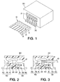
- terminals 5 are arranged in two, spaced apart rows, complementary to terminals 2. Each row contacts terminals 2 on one face of flat cable 1. The terminals are biased toward each other so that, when terminals 2 are inserted therebetween, good electrical contact is made.
- EP-A-0 519 317 discloses a connector having the features recited in the preamble of claim 1.
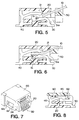
- the casing has support shelves for supporting the inserted leading end of the flat cable on both sides thereof at portions which are spaced the longitudinal direction of said leading end.
- the front contacts and rear contacts are also spaced from each other in the longitudinal direction of the cable end and are each arranged opposite a corresponding support shelve.
- the leading end of the cable is contacted at two points which are spaced in the longitudinal direction thereof, namely between the front terminals and a corresponding support shelf and between the rear terminals and a corresponding support shelf.
- the base has also been found useful to provide the base with a pair of spaced apart arms which are adapted to slide in complementary guide grooves on the walls of the casing.
- projections and detents can also be provided whereby the retainer is releasably locked in the desired operative position.
- retainer 50 is comprised of base 52 and arms 53 which have projections 53a at their distal ends.
- Complementary guide grooves 23 are located on the sides of casing 20 and are provided with projections 23a and 23b.
- arms 53 move in guide grooves 23 and projection 23b cooperates with projection 53a to hold retainer 50 in its initial position.
- projections 23a engage projections 53a, thereby securing retainer 50 in its operative position.
- Retainer 50 carries plate 51 which contains grooves 51a extending therethrough. Grooves 51a terminate short of the distal edge of plate 51.
Landscapes
- Coupling Device And Connection With Printed Circuit (AREA)
Claims (9)
- Connecteur pour un câble plat (10), le dit câble ayant une extrémité de tête pourvue d'une pluralité de bornes plates (13) sur les deux faces de la dite extrémité de tête,
le dit connecteur comprenant :caractérisé en ce que :un boítier (20) ayant une cavité à l'intérieur, la dite cavité s'étendant d'une ouverture avant (21) ménagée dans un côté avant du dit boítier à une ouverture arrière ménagée dans un côté arrière du dit boítier, la dite ouverture arrière étant distante de la dite ouverture avant, la dite cavité pouvant recevoir la dite extrémité de tête du dit câble (10) à travers la dite ouverture avant,une pluralité de bornes avant (30), complémentaires des dites bornes plates (13), placées dans la dite cavité et insérées à travers la dite ouverture avant (21), les dites bornes avant (30) ayant des contacts avant (33) qui s'étendent vers le dit côté arrière et peuvent venir en contact avec les dites bornes plates (13) sur une face de la dite extrémité de tête,une pluralité de bornes arrière (40), complémentaires des dites bornes plates (13), placées dans la dite cavité et insérées à travers la dite ouverture arrière, les dites bornes arrière (40) ayant des contacts arrière (43) qui s'étendent vers le dit côté avant et peuvent venir en contact avec les dites bornes plates (13) sur l'autre face de la dite extrémité de tête,il est prévu une pluralité de conducteurs avant (32), chacun en contact électrique avec au moins une des dites bornes avant (30) et s'étendant à l'extérieur du dit boítier, du dit côté avant, et une pluralité de conducteurs arrière (42), chacun en contact électrique avec au moins une des dites bornes arrière (40) et s'étendant à l'extérieur du dit boítier, du dit côté arrière, etles dits contacts avant (33) des bornes avant (30) et les dits contacts arrière (43) des bornes arrière (40) sont agencés de manière à définir une fente entre eux, la distance d'écartement de la dite fente étant plus petite que l'épaisseur de la dite extrémité de tête du câble (10) de sorte que les dits contacts avant (33) et les dits contacts arrière (43) sont en contact électrique avec la dite extrémité de tête lorsque la dite extrémité de tête est placée dans la fente entre les contacts avant (33) et les contacts arrière (43). - Connecteur selon la revendication 1, comprenant au moins un trou de fixation avant (22) ménagé dans le dit boítier (20) et prévu pour recevoir un élément de positionnement avant (31), et au moins un trou de fixation arrière (22) ménagé dans le dit boítier (20) et prévu pour recevoir un élément de positionnement arrière (41), le dit élément de positionnement avant (31) étant fixé à une des dites bornes avant (30) et le dit élément de positionnernent arrière (41) étant fixé à une des dites bornes arrière (40).
- Connecteur selon la revendication 1 ou 2, comprenant un élément de retenue (50,60) qui comporte une plaque (51) s'étendant vers les dites bornes avant ou les dites bornes arrière,
la dite plaque (51), lorsqu'elle est insérée dans la dite cavité dans une position initiale, provoquant une flexion d'au moins l'un d'un contact avant (33) sur la dite borne avant (30) et d'un contact arrière (43) sur la dite borne arrière (40), de façon à augmenter la dite distance entre le dit contact avant (33) et le dit contact arrière (43). - Connecteur .selon la revendication 1, dans lequel la dite plaque (51) comporte une rainure (51a) correspondant au dit contact avant (33) ou au dit contact arrière (43), la dite rainure (51a) s'étendant à travers la dite plaque (51) et se terminant avant son extrémité distale de sorte que, lorsqu'on insère la dite plaque (51) dans une position initiale dans la dite cavité, la dite extrémité distale dévie le dit contact avant (33) ou le dit contact arrière (43), ce qui augmente la dite distance, et, lorsqu'on déplace la dite plaque (51) à partir de la dite position initiale plus loin dans la dite cavité jusqu'à une position de travail, le dit contact avant (33) ou ledit contact arrière (43) passe au-dessus de la dite extrémité distale et traverse la dite rainure (51a), ce qui réduit la dite distance à une valeur inférieure à une épaisseur de la dite extrémité de tête.
- Connecteur selon la revendication 1, comprenant un élément de retenue (60) de forme sensiblement plane sur le dit boítier, le dit élément de retenue (60) ayant une surface plane, une paroi descendante située à un bord de queue de la dite surface plane, et une lèvre s'étendant vers l'avant sur la dite paroi descendante, la dite lèvre étant espacée de la dite surface plane et définissant une partie de réception (62) de la dite cavité, un bord distal de la dite lèvre pouvant rencontrer et provoquer une flexion d'un contact avant (33) sur la dite borne avant (30) ou d'un contact arrière (43) sur la dite borne arrière (40) lorsque le dit bord est complètement inséré dans la dite cavité, ce qui augmente une distance entre le dit contact avant (33) et le dit contact arrière (43).
- Connecteur selon la revendication 5, dans lequel la dite lèvre n'est pas en contact avec le dit contact avant (33) et le dit contact arrière (43) lorsque le dit élément de retenue (60) est au moins partiellement retiré de la dite cavité..
- Connecteur selon la revendication 3, dans lequel le dit élément de retenue (50) comprend au moins un bras (53) prévu pour coulisser dans une rainure de guidage complémentaire (23) sur une paroi du dit boítier.
- Connecteur selon la revendication 7, dans lequel chaque dite rainure de guidage (23) contient une première saillie (32), chacun des dits bras ayant une indentation complémentaire (53a), la dite indentation (53a) bloquant de façon libérable le dit élément de retenue (50, 60) sur le dit boítier (20) lorsque le dit élément de retenue (50,60) est dans ladite position de travail.
- Connecteur selon la revendication 7 ou 8, dans lequel chaque dite rainure de guidage (23) contient une deuxième saillie (23a), la dite indentation (53a) retenant de façon libérable le dit élément de retenue (50, 60) sur le dit boítier (20) dans la dite position initiale.
Applications Claiming Priority (3)
| Application Number | Priority Date | Filing Date | Title |
|---|---|---|---|
| JP330375/95 | 1995-12-19 | ||
| JP33037595 | 1995-12-19 | ||
| JP07330375A JP3104600B2 (ja) | 1995-12-19 | 1995-12-19 | フラットケーブル用コネクタ |
Publications (2)
| Publication Number | Publication Date |
|---|---|
| EP0780931A1 EP0780931A1 (fr) | 1997-06-25 |
| EP0780931B1 true EP0780931B1 (fr) | 2000-10-11 |
Family
ID=18231904
Family Applications (1)
| Application Number | Title | Priority Date | Filing Date |
|---|---|---|---|
| EP96120549A Expired - Lifetime EP0780931B1 (fr) | 1995-12-19 | 1996-12-19 | Connecteur pour des câbles plats |
Country Status (4)
| Country | Link |
|---|---|
| US (1) | US5775938A (fr) |
| EP (1) | EP0780931B1 (fr) |
| JP (1) | JP3104600B2 (fr) |
| DE (1) | DE69610605T2 (fr) |
Families Citing this family (18)
| Publication number | Priority date | Publication date | Assignee | Title |
|---|---|---|---|---|
| US6050858A (en) * | 1998-06-25 | 2000-04-18 | Hon Hai Precision Ind. Co., Ltd. | Electrical connector with improved electrical contacts |
| US6089925A (en) * | 1998-10-06 | 2000-07-18 | The Whitaker Corporation | Modular electrical connector having electrical contact modules |
| US7044773B2 (en) | 2002-08-01 | 2006-05-16 | Ddk Ltd. | Connector |
| DE10249683B4 (de) * | 2002-10-25 | 2006-10-05 | Küster Automotive Door Systems GmbH | Kontaktklemme zur elektr. Kontaktierung eines Gegenkontaktes, insb. für den Einsatz bei elektrischen Kraftfahrzeugkomponenten, wie bspw. Fensterhebersystemen o. dgl. |
| CN101032060B (zh) * | 2004-07-07 | 2010-08-25 | 莫莱克斯公司 | 具有用于正确连接的键式装置的边缘卡连接器 |
| JP4578931B2 (ja) | 2004-10-18 | 2010-11-10 | 第一電子工業株式会社 | コネクタ |
| JP4915759B2 (ja) * | 2004-12-22 | 2012-04-11 | Smk株式会社 | フレキシブル基板接続用コネクタ |
| JP2006179408A (ja) * | 2004-12-24 | 2006-07-06 | Smk Corp | コネクタ |
| US7413469B2 (en) * | 2005-10-11 | 2008-08-19 | Tyco Electronics Corporation | Electrical connector |
| KR20070057301A (ko) * | 2005-12-01 | 2007-06-07 | 삼성전자주식회사 | 연성 인쇄 회로용 커넥터와, 그에 삽입되는 연성 인쇄 회로및 이를 갖는 표시 장치 |
| JP2006261140A (ja) * | 2006-07-06 | 2006-09-28 | D D K Ltd | コネクタ |
| JP5073572B2 (ja) * | 2008-04-25 | 2012-11-14 | タイコエレクトロニクスジャパン合同会社 | 電気コネクタ |
| JP5643550B2 (ja) * | 2010-06-14 | 2014-12-17 | 日本航空電子工業株式会社 | コネクタ及びそれを備えるコネクタ組立体 |
| JP2011023371A (ja) * | 2010-11-04 | 2011-02-03 | D D K Ltd | コネクタ |
| CN102832480B (zh) * | 2011-06-16 | 2016-02-03 | 富士康(昆山)电脑接插件有限公司 | 电连接器 |
| US8696389B2 (en) * | 2011-09-30 | 2014-04-15 | Tyco Electronics Corporation | Card edge connector |
| JP2012182150A (ja) * | 2012-05-25 | 2012-09-20 | D D K Ltd | コネクタ |
| JP6293634B2 (ja) * | 2014-10-03 | 2018-03-14 | 日本航空電子工業株式会社 | コネクタ |
Family Cites Families (4)
| Publication number | Priority date | Publication date | Assignee | Title |
|---|---|---|---|---|
| JPH0635415Y2 (ja) * | 1989-10-06 | 1994-09-14 | コネクタ | |
| JPH04206374A (ja) | 1990-11-30 | 1992-07-28 | Canon Inc | プリント基板の接続装置 |
| JPH069152B2 (ja) * | 1991-06-18 | 1994-02-02 | モレックス インコーポレーテッド | 水平基板接続用カードエッヂコネクタ及びその製法 |
| JPH07230860A (ja) * | 1994-02-09 | 1995-08-29 | Molex Inc | 電気コネクタ |
-
1995
- 1995-12-19 JP JP07330375A patent/JP3104600B2/ja not_active Expired - Fee Related
-
1996
- 1996-12-19 EP EP96120549A patent/EP0780931B1/fr not_active Expired - Lifetime
- 1996-12-19 DE DE69610605T patent/DE69610605T2/de not_active Expired - Fee Related
- 1996-12-19 US US08/767,955 patent/US5775938A/en not_active Expired - Fee Related
Also Published As
| Publication number | Publication date |
|---|---|
| JPH09171858A (ja) | 1997-06-30 |
| US5775938A (en) | 1998-07-07 |
| DE69610605T2 (de) | 2001-05-23 |
| DE69610605D1 (de) | 2000-11-16 |
| JP3104600B2 (ja) | 2000-10-30 |
| EP0780931A1 (fr) | 1997-06-25 |
Similar Documents
| Publication | Publication Date | Title |
|---|---|---|
| US5775938A (en) | Connector for flat cables | |
| US4708415A (en) | Electrical connectors | |
| US6162083A (en) | Electrical connector system for flat circuitry | |
| US6729890B2 (en) | Reduced-size board-to-board connector | |
| US5181854A (en) | Press-contact type electric connector for a flat, flexible cable | |
| US5194017A (en) | Connector for a flexible circuit | |
| US5244412A (en) | Electrical device for surface mounting on a circuit board and mounting component thereof | |
| US4647136A (en) | Modular plug and printed circuit connector | |
| US5800204A (en) | Electrical connector for flat cable | |
| US5037334A (en) | Connector with equal lateral force contact spacer plate | |
| EP0519317B1 (fr) | Connecteur de bord pour contenir et maintenir un câble plat en parallèle au circuit imprimée | |
| US6056571A (en) | Electrical connector for flat electrical conductor | |
| US5080596A (en) | Connector with contact spacer plate providing greater lateral force on rear contacts | |
| GB1569502A (en) | Circuit package connector | |
| US4645277A (en) | Connector for connecting boards | |
| US20070249217A1 (en) | Electrical connector with improved terminals | |
| US4984996A (en) | Printed circuit board edge connector | |
| KR100288727B1 (ko) | 평면 회로용 전기 커넥터 | |
| EP0851539A2 (fr) | Connecteur pour des câbles plats | |
| EP1349240B1 (fr) | Connecteur avec contact dont le mouvement pour part est guidé par isolant | |
| US4919626A (en) | Connector for IC card | |
| IE914105A1 (en) | Electrical connector assembly for mounting on a printed circuit board | |
| EP0454977B1 (fr) | Connecteur à fiche électrique ayant des bandes de contacts encastrées dans une plaque isolante pour application aux plaquettes de circuits | |
| US5597320A (en) | Zero insertion force electrical connector and terminal | |
| US6371772B1 (en) | Electrical connector with enhanced contacts |
Legal Events
| Date | Code | Title | Description |
|---|---|---|---|
| PUAI | Public reference made under article 153(3) epc to a published international application that has entered the european phase |
Free format text: ORIGINAL CODE: 0009012 |
|
| AK | Designated contracting states |
Kind code of ref document: A1 Designated state(s): DE FR GB |
|
| 17P | Request for examination filed |
Effective date: 19970526 |
|
| 17Q | First examination report despatched |
Effective date: 19990401 |
|
| GRAG | Despatch of communication of intention to grant |
Free format text: ORIGINAL CODE: EPIDOS AGRA |
|
| 17Q | First examination report despatched |
Effective date: 19990401 |
|
| GRAG | Despatch of communication of intention to grant |
Free format text: ORIGINAL CODE: EPIDOS AGRA |
|
| GRAH | Despatch of communication of intention to grant a patent |
Free format text: ORIGINAL CODE: EPIDOS IGRA |
|
| RIC1 | Information provided on ipc code assigned before grant |
Free format text: 7H 01R 12/24 A |
|
| GRAH | Despatch of communication of intention to grant a patent |
Free format text: ORIGINAL CODE: EPIDOS IGRA |
|
| GRAA | (expected) grant |
Free format text: ORIGINAL CODE: 0009210 |
|
| AK | Designated contracting states |
Kind code of ref document: B1 Designated state(s): DE FR GB |
|
| REF | Corresponds to: |
Ref document number: 69610605 Country of ref document: DE Date of ref document: 20001116 |
|
| ET | Fr: translation filed | ||
| PLBE | No opposition filed within time limit |
Free format text: ORIGINAL CODE: 0009261 |
|
| STAA | Information on the status of an ep patent application or granted ep patent |
Free format text: STATUS: NO OPPOSITION FILED WITHIN TIME LIMIT |
|
| 26N | No opposition filed | ||
| REG | Reference to a national code |
Ref country code: GB Ref legal event code: IF02 |
|
| PGFP | Annual fee paid to national office [announced via postgrant information from national office to epo] |
Ref country code: FR Payment date: 20021210 Year of fee payment: 7 |
|
| PGFP | Annual fee paid to national office [announced via postgrant information from national office to epo] |
Ref country code: GB Payment date: 20021218 Year of fee payment: 7 |
|
| PGFP | Annual fee paid to national office [announced via postgrant information from national office to epo] |
Ref country code: DE Payment date: 20021219 Year of fee payment: 7 |
|
| PG25 | Lapsed in a contracting state [announced via postgrant information from national office to epo] |
Ref country code: GB Free format text: LAPSE BECAUSE OF NON-PAYMENT OF DUE FEES Effective date: 20031219 |
|
| PG25 | Lapsed in a contracting state [announced via postgrant information from national office to epo] |
Ref country code: DE Free format text: LAPSE BECAUSE OF NON-PAYMENT OF DUE FEES Effective date: 20040701 |
|
| GBPC | Gb: european patent ceased through non-payment of renewal fee |
Effective date: 20031219 |
|
| PG25 | Lapsed in a contracting state [announced via postgrant information from national office to epo] |
Ref country code: FR Free format text: LAPSE BECAUSE OF NON-PAYMENT OF DUE FEES Effective date: 20040831 |
|
| REG | Reference to a national code |
Ref country code: FR Ref legal event code: ST |