EP0780936A2 - Méthode pour la sélection de la longueur d'onde dans un laser à longueur d'onde accordable - Google Patents
Méthode pour la sélection de la longueur d'onde dans un laser à longueur d'onde accordable Download PDFInfo
- Publication number
- EP0780936A2 EP0780936A2 EP96120284A EP96120284A EP0780936A2 EP 0780936 A2 EP0780936 A2 EP 0780936A2 EP 96120284 A EP96120284 A EP 96120284A EP 96120284 A EP96120284 A EP 96120284A EP 0780936 A2 EP0780936 A2 EP 0780936A2
- Authority
- EP
- European Patent Office
- Prior art keywords
- laser
- wavelength
- acousto
- optic crystal
- inputted
- Prior art date
- Legal status (The legal status is an assumption and is not a legal conclusion. Google has not performed a legal analysis and makes no representation as to the accuracy of the status listed.)
- Granted
Links
Images


Classifications
-
- H—ELECTRICITY
- H01—ELECTRIC ELEMENTS
- H01S—DEVICES USING THE PROCESS OF LIGHT AMPLIFICATION BY STIMULATED EMISSION OF RADIATION [LASER] TO AMPLIFY OR GENERATE LIGHT; DEVICES USING STIMULATED EMISSION OF ELECTROMAGNETIC RADIATION IN WAVE RANGES OTHER THAN OPTICAL
- H01S3/00—Lasers, i.e. devices using stimulated emission of electromagnetic radiation in the infrared, visible or ultraviolet wave range
- H01S3/10—Controlling the intensity, frequency, phase, polarisation or direction of the emitted radiation, e.g. switching, gating, modulating or demodulating
- H01S3/106—Controlling the intensity, frequency, phase, polarisation or direction of the emitted radiation, e.g. switching, gating, modulating or demodulating by controlling devices placed within the cavity
- H01S3/1068—Controlling the intensity, frequency, phase, polarisation or direction of the emitted radiation, e.g. switching, gating, modulating or demodulating by controlling devices placed within the cavity using an acousto-optical device
-
- G—PHYSICS
- G02—OPTICS
- G02F—OPTICAL DEVICES OR ARRANGEMENTS FOR THE CONTROL OF LIGHT BY MODIFICATION OF THE OPTICAL PROPERTIES OF THE MEDIA OF THE ELEMENTS INVOLVED THEREIN; NON-LINEAR OPTICS; FREQUENCY-CHANGING OF LIGHT; OPTICAL LOGIC ELEMENTS; OPTICAL ANALOGUE/DIGITAL CONVERTERS
- G02F1/00—Devices or arrangements for the control of the intensity, colour, phase, polarisation or direction of light arriving from an independent light source, e.g. switching, gating or modulating; Non-linear optics
- G02F1/01—Devices or arrangements for the control of the intensity, colour, phase, polarisation or direction of light arriving from an independent light source, e.g. switching, gating or modulating; Non-linear optics for the control of the intensity, phase, polarisation or colour
- G02F1/11—Devices or arrangements for the control of the intensity, colour, phase, polarisation or direction of light arriving from an independent light source, e.g. switching, gating or modulating; Non-linear optics for the control of the intensity, phase, polarisation or colour based on acousto-optical elements, e.g. using variable diffraction by sound or like mechanical waves
- G02F1/116—Devices or arrangements for the control of the intensity, colour, phase, polarisation or direction of light arriving from an independent light source, e.g. switching, gating or modulating; Non-linear optics for the control of the intensity, phase, polarisation or colour based on acousto-optical elements, e.g. using variable diffraction by sound or like mechanical waves using an optically anisotropic medium, wherein the incident and the diffracted light waves have different polarizations, e.g. acousto-optic tunable filter [AOTF]
Definitions
- the present invention relates to a wavelength selecting method in a wavelength tunable laser as well as a wavelength selectable laser oscillator in a wavelength tunable laser, and more particularly to a wavelength selecting method and a wavelength selectable laser oscillator which can control a laser oscillation wavelength by an electrical means at high scanning rate and in a highly reliable manner in a wavelength tunable laser.
- wavelength tunable laser solid laser wherein a crystal such as Ti:Al 2 O 3 (titanium sapphire) and the like is utilized as a laser medium and liquid laser wherein a dye solution and the like is utilized as a laser medium have been widely employed.
- a wavelength selecting method in laser-oscillation for wavelength tunable laser as described above in a desired wavelength there has been, for example, a wavelength selecting method wherein a diffraction gating, a birefringent plate or the like is disposed in a laser resonator containing a wavelength tunable laser medium, such diffraction gating, birefringent plate or the like as described above is mechanically rotated, whereby only the light rays having a desired wavelength is picked up from among light rays outputted from the wavelength tunable laser medium, and the light rays thus picked up are allowed to reflect within the wavelength tunable laser resonator to grow to start laser oscillation, so that only the laser light rays having a desired wavelength are outputted from the laser resonator.
- the electrical wavelength sweeping method of pulsed dye laser proposed by Taylor et al. is the one wherein CaMoO 4 crystal is placed in a dye solution being a laser medium, acoustic waves are inputted to the CaMoO 4 crystal, and a resonator is constituted by light ray components which interact with the acoustic waves thereby permitting an oscillating wavelength of the laser to be tunable.
- an object of the present invention is to provide a wavelength selecting method in a wavelength tunable laser and a wavelength selectable laser oscillator in a wavelength tunable laser by which a laser wavelength is electrically controlled to be capable of sweeping the wavelength at a high speed, whereby miniaturization of the whole equipment is intended, besides a stable wavelength selecting action can be realized by employing an acousto-optic crystal which has been widely spread and has high reliability as an independent component without accompanying any mechanically movable section such as a rotating mechanism and the like.
- the wavelength selecting method in a wavelength tunable laser and a wavelength selectable laser oscillator in a wavelength tunable laser according to the present invention has been made in a quite different point of view from a conventional manner wherein a usual diffraction grating, birefringent plate or the like is employed.
- the present invention has been made with aiming at such a point that when acoustic waves are generated in an acousto-optic crystal such as TeO 2 crystal and the like having birefringent characteristics, a plane of polarization of the diffraction light rays having a specified wavelength in response to a frequency of the acoustic waves among the light rays inputted to the crystal not only comes to be orthogonal with respect to the plane of polarization of nondiffraction light rays, but also an output angle of the diffraction light rays deflects so as to be significantly different from that of the nondiffraction light rays.
- an acousto-optic crystal such as TeO 2 crystal and the like having birefringent characteristics
- FIG. 1 is a conceptual diagram indicating wavelength selecting action wherein polarizing action of light rays having a specified wavelength derived from acoustic waves is shown in which inputting light rays 102 having a wavelength ⁇ i and an angle frequency ⁇ i is inputted into an acousto-optic crystal 100 having birefringent properties. Furthermore, when acoustic waves 104 having a frequency ⁇ a is applied into an acousto-optic crystal 100, diffraction light rays 106 are obtained.
- a laser resonator wherein the diffraction light rays reciprocates between the total reflection mirror 110 and the output mirror 112 is constituted.
- a wavelength of the diffraction light rays 106 is decided dependent upon a wavelength of the acoustic waves 104 generated in the acousto-optic crystal 100, so that, for instance, a piezoelectric element driven by an RF power source is attached to the acousto-optic crystal 100 and when the piezoelectric element is driven by the RF power source to produce distortion in the piezoelectric element, tunable control of the laser wavelength becomes possible by controlling a frequency of the RF power source in the case where the acoustic waves 104 having the frequency in response to the distortion produced are inputted to the acousto-optic crystal 100.
- diffraction efficiency to the diffraction light rays 106 is determined by acoustic wave intensity, loss in the laser resonator is controlled, when input intensity of the RF power source is controlled, and as a result tunable control of a laser output becomes possible.
- a diffraction angle ⁇ 109 is not completely constant with respect to the wavelength of the diffraction light rays 106, so that a wavelength range in which the laser resonator can be constituted by means of vertical reflection of the total reflection mirror 110 with respect to the diffraction light rays 106 is narrow, thus a configuration angle of the total reflection mirror 110 must be adjusted bit by bit for the sake of making laser oscillation in a wide wavelength region, and as a result there is such a fear that the adjusting operation becomes complicated from practical point of view. For this reason, it is required to correct deflections of the diffraction angle ⁇ 109 by the use of any means for the sake of expanding a tunable wavelength range without changing the configuration angle of the total reflection mirror 110.
- an optical element dispersing a wavelength of light rays such as a triangular prism may be employed in such a manner that light rays having wavelengths of ⁇ 1, ⁇ 2 and a deflection angle ⁇ proceed in substantially parallel after passing through the triangular prism.
- a laser resonator for wide wavelength region can be constituted.
- an expanding means of the laser beam such as a telescope for expanding a beam diameter inputted to the acousto-optic crystal 100 is disposed in the laser resonator, whereby a possibility of damaging the acousto-optic crystal 100 can be reduced.
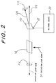
- FIG. 2 is an explanatory diagram showing a schematic constitution of a wavelength selectable laser oscillator (hereinafter referred to simply as "laser oscillator”) in a wavelength tunable laser for executing a wavelength selecting method in the wavelength tunable laser according to the first manner of practice of the present invention.
- laser oscillator a wavelength selectable laser oscillator
- FIG. 1 the same constitutional components as those shown in FIG. 1 are represented by the same reference numerals as that of FIG. 1 in FIG. 2 for easy understanding.
- a laser resonator is constituted by a mirror having a prescribed transmittance on the output side 112 and a total reflection mirror 110.
- a Ti:Al 2 O 3 laser crystal 14 and an acousto-optic crystal 100 are disposed in this order along the direction extending from the side of the mirror on the output side 112 to the side of the total reflection mirror 110 as the wavelength tunable laser and the crystal for selecting wavelength, respectively.
- a piezoelectric element 22 driven by an RF power source 20 as the acoustic wave inputting means.
- acoustic waves having a frequency in response to the distortion thus produced is inputted to the acousto-optic crystal 100 on the basis of the aforesaid distortion of the piezoelectric element 22.
- the total reflection mirror 110 is constituted so as to reflect only the diffraction light rays 106 diffracted in a prescribed direction by the acousto-optic crystal 100.
- the piezoelectric element 22 is constituted in such that acoustic waves are inputted to the acousto-optic crystal 100 in accordance with such a manner that only the light rays having a wavelength of outputting laser beam which is desired to output from the output mirror 112 are diffracted.
- second higher harmonics of an Nd:YAG laser is employed as excitation laser beam 24 to excite the Ti:Al 2 O 3 laser crystal 14.
- a frequency of the RF power source 20 is controlled in response to a wavelength of the outputting laser beam which is desired to output from the outputting mirror 112 to drive the piezoelectric element 22.
- the outputting light rays having a wavelength in response to the frequency of the RF power source 20 are diffracted in a prescribed direction to be outputted from the acousto-optic crystal 100 as the diffraction light rays 106 among outputting light rays having a wide range of wavelength zone outputted from the Ti:Al 2 O 3 laser crystal 14 which were inputted to the acousto-optic crystal 100.
- the diffraction light rays 106 which are outputted from the acousto-optic crystal 100 and diffracted in a prescribed direction are reflected by the total reflection mirror 110 to reciprocate the same in the laser resonator.
- FIG. 3 is a schematic diagram showing a constitution of the laser oscillator according to the second manner of practice of the present invention wherein the same constitutional components as those shown in FIGS. 1 and 2 are represented by the same reference numerals as that of these FIGURES in FIG. 3 for easy understanding.
- a laser resonator is constituted by an output mirror 112 having a prescribed transmittance and a total reflection mirror 110 in the same way as in the laser oscillator according to the first manner of practice.
- a Ti:Al 2 O 3 laser crystal 14 In the laser resonator, a Ti:Al 2 O 3 laser crystal 14, an acousto-optic crystal 100, and a prism for correcting diffraction light rays 28 are disposed in this order along the direction extending from the side of the output mirror 112 to the side of the total reflection mirror 110, respectively.
- the prism for correcting diffraction light rays 28 is constituted so as to always output diffraction light rays 106 outputted from the acousto-optic crystal 100 in a constant direction irrespective of wavelength, and the total reflection mirror 110 is constituted so as to reflect the light rays outputted from the prism for correcting diffraction light rays 28.
- a piezoelectric element 22 is constituted in such that acoustic waves are inputted to the acousto-optic crystal 100 so as to diffract only the outputting light rays having a wavelength of the outputting laser beam which is desired to output from the output mirror 112 in a prescribed direction.
- the second harmonics of an Nd:YAG laser is used as an excitation laser beam 24 to excite the Ti:Al 2 O 3 laser crystal 14. Furthermore, based on the above described principle, a frequency of an RF power source 20 is controlled in response to a given wavelength of the laser which is set to output from the output mirror 112 by driving the piezoelectric element 22.
- the outputting light rays having a wavelength in response to the frequency of the RF power source 20 are diffracted in a prescribed direction to be outputted from the acousto-optic crystal 100 as the diffraction light rays 106 among outputting light rays having a wide range of wavelength zone outputted from the Ti:Al 2 O 3 laser crystal 14 which were inputted to the acousto-optic crystal 100.
- the diffraction light rays 106 which are diffracted in a prescribed direction and outputted from the acousto-optic crystal 100 are inputted to the prism for correcting diffraction light rays 28 and outputted in a constant direction.
- light rays outputted from the prism for correcting diffraction light rays 28 are reflected by the total reflection mirror 110, whereby they reciprocate in the laser resonator.
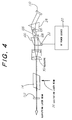
- FIG. 4 is a schematic diagram showing a constitution of the laser oscillator according to the third manner of practice of the present invention wherein the same constitutional components as those shown in FIGS. 1, 2 and 3 are represented by the same reference numerals as that of these FIGURES in FIG. 4 for easy understanding.
- a laser resonator is constituted by an output mirror 112 having a prescribed transmittance and a total reflection mirror 110 in the same way as in the laser oscillator according to the second manner of practice.
- a Ti:Al 2 O 3 laser crystal 14 In the laser resonator, a Ti:Al 2 O 3 laser crystal 14, a telescope for adjusting beam diameter 30, an acousto-optic crystal 100, and a prism for correcting diffraction light rays 28 are disposed in this order along the direction extending from the side of the output mirror 112 to the side of the total reflection mirror 110, respectively.
- the telescope 30 is constituted in such that a beam diameter of light rays inputted to the acousto-optic crystal 100 can be enlarged in a desired size.
- the prism for correcting diffraction light rays 28 is constituted so as to always output the light rays outputted from the acousto-optic crystal 100 in a constant direction irrespective of wavelength
- the total reflection mirror 110 is constituted so as to reflect the light rays outputted from the prism for correcting diffraction light rays 28 in the same way as in the second manner of practice.
- a piezoelectric element 22 is constituted in such that acoustic waves are inputted to the acousto-optic crystal 100 so as to diffract only the outputting light rays having a wavelength of the outputting laser beam which is desired to output from the output mirror 112 in a prescribed direction.
- the second harmonics of an Nd:YAG laser is used as an excitation laser beam 24 to excite the Ti:Al 2 O 3 laser crystal 14. Furthermore, based on the above described principle, a frequency of an RF power source 20 is controlled in response to a wavelength of the outputting laser beam which is desired to output from the output mirror 112 by driving the piezoelectric element 22.
- the outputting light rays having a wide range of wavelength zone and outputted from the Ti:Al 2 O 3 laser crystal 14 are inputted to the acousto-optic crystal 100 with expansion to a desired size in the beam diameter thereof by means of the telescope 30.
- Outputting light rays having a wavelength in response to the frequency of an RF power source 20 are diffracted in a prescribed direction to be outputted from the acousto-optic crystal 100 as diffracted light rays 106 among the outputting light rays outputted from the Ti:Al 2 O 3 laser crystal 14 having a wide range of wavelength zone which were inputted to the acousto-optic crystal 100 by way of the telescope 30. Furthermore, the diffraction light rays 106 outputted from the acousto-optic crystal 100 which had been diffracted in a prescribed direction are inputted to the prism for correcting diffraction light rays 28 to be outputted in a constant direction. Then, the light rays outputted from the prism for correcting diffraction light rays 28 are reflected by the total reflection mirror 110, whereby they reciprocate in the laser resonator.
- FIG. 5 is a graphical representation showing results of experiments by the use of the laser oscillator illustrated in the first manner of practice shown in FIG. 2 under the following experimental conditions which indicates a relationship between the output of an outputting laser beam and the wavelength in the case where a frequency of the RF power source 20 is changed.
- laser oscillation can be conducted by selecting an arbitrary wavelength within a wavelength range of from about 800 nm to about 811 nm.
- FIG. 6 is a graphical representation showing results of experiments by the use of the laser oscillator illustrated in the third manner of practice shown in FIG. 4 under the following experimental conditions which indicates a relationship between the output of outputting laser beam and the wavelength in the case where a frequency of the RF power source 20 is changed.
- laser oscillation can be conducted by selecting an arbitrary wavelength within a wavelength range of from about 750 nm to about 850 nm.
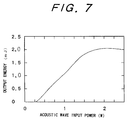
- FIG. 7 indicates changes in an output of the outputting laser beam in the case where intensity of the acoustic waves 104 inputted to the acousto-optic crystal 100 is changed by employing the laser oscillator shown in the second manner of practice of FIG. 3.
- intensity of the acoustic waves 104 inputted to the acousto-optic crystal 100 changes from 0.5 W to 2.0 W
- the output of the outputting laser beam changes also in response thereto, so that when the intensity of the acoustic waves 104 inputted to the acousto-optic crystal 100 is varied, it becomes possible to change the output of outputting laser beam.
- the wavelength of an outputting laser beam can be selected without providing any mechanically movable section such as a rotating mechanism and the like, miniaturization of the whole equipment can be intended, besides a stable wavelength selecting action can be realized.
- the present invention has been constituted to electrically control a laser wavelength to sweep the wavelength at high scanning rate with the provision of no mechanically movable section such as a rotating mechanism and the like, so that it becomes possible to intend miniaturization of the whole equipment, besides since an acousto-optic crystal which is widely used and has high reliability may be employed as an independent component, whereby the present invention can realize a stable wavelength selecting action.
- an optical element for correcting a deflection angle of diffraction light rays such as a prism for correcting diffraction light rays and the like is employed, it becomes possible to output an outputting laser beam in a wide rage of a wavelength region.
- an expanding means for controlling a beam diameter of light rays inputted to an acousto-optic crystal such as a telescope and the like is employed, light intensity of the light rays inputted to the acousto-optic crystal per unit area thereof can be reduced, whereby it becomes possible to realize outputting laser beam of a high output while suppressing damage of the acousto-optic crystal.
Landscapes
- Physics & Mathematics (AREA)
- Electromagnetism (AREA)
- Engineering & Computer Science (AREA)
- Plasma & Fusion (AREA)
- Optics & Photonics (AREA)
- Lasers (AREA)
Applications Claiming Priority (3)
| Application Number | Priority Date | Filing Date | Title |
|---|---|---|---|
| JP348782/95 | 1995-12-19 | ||
| JP34878295 | 1995-12-19 | ||
| JP34878295A JP3421184B2 (ja) | 1995-12-19 | 1995-12-19 | 波長可変レーザーにおける波長選択方法および波長可変レーザーにおける波長選択可能なレーザー発振装置 |
Publications (3)
| Publication Number | Publication Date |
|---|---|
| EP0780936A2 true EP0780936A2 (fr) | 1997-06-25 |
| EP0780936A3 EP0780936A3 (fr) | 1998-01-28 |
| EP0780936B1 EP0780936B1 (fr) | 2002-03-27 |
Family
ID=18399330
Family Applications (1)
| Application Number | Title | Priority Date | Filing Date |
|---|---|---|---|
| EP96120284A Expired - Lifetime EP0780936B1 (fr) | 1995-12-19 | 1996-12-17 | Méthode pour sélectionner la longueur d'onde dans un laser à longueur d'onde accordable et oscillateur à longueur d'onde sélectionnable dans un laser à longueur d'onde accordable |
Country Status (4)
| Country | Link |
|---|---|
| US (1) | US5835512A (fr) |
| EP (1) | EP0780936B1 (fr) |
| JP (1) | JP3421184B2 (fr) |
| DE (1) | DE69620126T2 (fr) |
Cited By (3)
| Publication number | Priority date | Publication date | Assignee | Title |
|---|---|---|---|---|
| EP0805532B1 (fr) * | 1996-04-30 | 2000-09-27 | Rikagaku Kenkyusho | Oscillateur paramétrique optique |
| EP0805531B1 (fr) * | 1996-04-30 | 2003-02-12 | Rikagaku Kenkyusho | Laser à longueur d'onde accordable |
| EP0805530B1 (fr) * | 1996-04-30 | 2003-02-12 | Rikagaku Kenkyusho | Laser à longueur d'onde accordable |
Families Citing this family (24)
| Publication number | Priority date | Publication date | Assignee | Title |
|---|---|---|---|---|
| US5970077A (en) * | 1997-04-25 | 1999-10-19 | Zygo Corporation | Apparatus for efficiently transforming a single frequency, linearly polarized laser beam into principally two orthogonally polarized beams having different frequencies |
| US6018536A (en) * | 1998-11-20 | 2000-01-25 | Sarnoff Corporation | Multiple-wavelength mode-locked laser |
| US6157660A (en) * | 1999-06-04 | 2000-12-05 | Zygo Corporation | Apparatus for generating linearly-orthogonally polarized light beams |
| JP2001244530A (ja) * | 2000-02-28 | 2001-09-07 | Inst Of Physical & Chemical Res | 超短パルスレーザー発振装置 |
| DE10127014A1 (de) * | 2001-06-01 | 2002-12-12 | Zeiss Carl Jena Gmbh | Laser mit veränderbarer Wellenlänge |
| US6717964B2 (en) * | 2001-07-02 | 2004-04-06 | E20 Communications, Inc. | Method and apparatus for wavelength tuning of optically pumped vertical cavity surface emitting lasers |
| US7088758B2 (en) | 2001-07-27 | 2006-08-08 | Cymer, Inc. | Relax gas discharge laser lithography light source |
| US7154928B2 (en) * | 2004-06-23 | 2006-12-26 | Cymer Inc. | Laser output beam wavefront splitter for bandwidth spectrum control |
| US6959024B2 (en) * | 2002-02-28 | 2005-10-25 | Picarro, Inc. | Laser Tuning by spectrally dependent spatial filtering |
| US7218443B2 (en) * | 2003-02-25 | 2007-05-15 | Toptica Photonics Ag | Generation of tunable light pulses |
| US7170913B2 (en) * | 2003-06-19 | 2007-01-30 | Multiwave Photonics, Sa | Laser source with configurable output beam characteristics |
| US20070160325A1 (en) * | 2006-01-11 | 2007-07-12 | Hyungbin Son | Angle-tunable transmissive grating |
| KR100793867B1 (ko) * | 2006-04-28 | 2008-01-15 | 현대자동차주식회사 | 차량의 연소 및 배기가스의 광계측용 파장가변 레이저장치 |
| WO2010029663A1 (fr) * | 2008-09-09 | 2010-03-18 | 株式会社メガオプト | Laser à fibre optique à synchronisation des modes, et procédé d'oscillation d'un laser à impulsions utilisant un laser à fibre optique à synchronisation des modes |
| SG11201505616YA (en) | 2013-01-18 | 2015-09-29 | Univ Yale | Superconducting device with at least one enclosure |
| JP6360499B2 (ja) | 2013-01-18 | 2018-07-18 | イェール ユニバーシティーYale University | 少なくとも1つの囲いを有する超伝導デバイスを製造するための方法 |
| US10468740B2 (en) | 2015-02-27 | 2019-11-05 | Yale University | Techniques for coupling planar qubits to non-planar resonators and related systems and methods |
| EP3589581B1 (fr) | 2017-02-28 | 2024-06-05 | Yale University | Techniques de couplage de bits quantiques à des résonateurs acoustiques, et systèmes et procédés associés |
| US12030085B2 (en) * | 2017-02-28 | 2024-07-09 | Yale University | Acousto-optic coupling techniques and related systems and methods |
| US11223355B2 (en) | 2018-12-12 | 2022-01-11 | Yale University | Inductively-shunted transmon qubit for superconducting circuits |
| FR3096792B1 (fr) * | 2019-05-28 | 2025-05-16 | Leosphere | Architectures de Modulateur Acousto-Optique, de dispositif optique et d’amplificateur optique fibré en double passage. |
| CN113219684A (zh) * | 2021-05-08 | 2021-08-06 | 武汉菲联光电科技有限公司 | 一种声光调制器 |
| CN115963060B (zh) * | 2021-10-13 | 2026-04-14 | 北京鉴知技术有限公司 | 扫频激光器及其控制方法、光学相干层析成像系统 |
| CN116937310A (zh) * | 2023-08-23 | 2023-10-24 | 湖北华中长江光电科技有限公司 | 一种波长可调谐的中红外激光器 |
Family Cites Families (7)
| Publication number | Priority date | Publication date | Assignee | Title |
|---|---|---|---|---|
| US4250466A (en) * | 1978-10-23 | 1981-02-10 | The United States Of America As Represented By The Secretary Of The Navy | Multiple pulse laser |
| GB8413502D0 (en) * | 1984-05-25 | 1984-07-04 | British Telecomm | Mode locked laser light sources |
| GB2215074A (en) * | 1988-02-17 | 1989-09-13 | Gen Electric Co Plc | Acousto-optic tunable filter |
| US5121245A (en) * | 1989-04-06 | 1992-06-09 | Electro Scientific Industries, Inc. | Laser system incorporating an acousto-optic device having reduced susceptibility to stress-induced birefringence |
| US5022034A (en) * | 1989-06-27 | 1991-06-04 | May A D | Laser device, including control of polarization mode |
| US5260953A (en) * | 1992-09-08 | 1993-11-09 | Alcon Surgical, Inc. | Tunable solid-state laser |
| US5521930A (en) * | 1994-07-19 | 1996-05-28 | Suni; Paul J. M. | Device for injection-seeding, frequency-shifting, and q-switching a laser source |
-
1995
- 1995-12-19 JP JP34878295A patent/JP3421184B2/ja not_active Expired - Fee Related
-
1996
- 1996-12-17 EP EP96120284A patent/EP0780936B1/fr not_active Expired - Lifetime
- 1996-12-17 DE DE69620126T patent/DE69620126T2/de not_active Expired - Lifetime
- 1996-12-19 US US08/769,989 patent/US5835512A/en not_active Expired - Lifetime
Non-Patent Citations (1)
| Title |
|---|
| TAYLOR D.J. ET AL.: "Electronic Tuning of Dye Laser using the Acousto-Optic Filter.", APPLIED PHYSICS LETTERS., vol. 19, no. 8, 15 October 1971 (1971-10-15), pages 269 - 271, XP002047237, DOI: doi:10.1063/1.1653913 |
Cited By (3)
| Publication number | Priority date | Publication date | Assignee | Title |
|---|---|---|---|---|
| EP0805532B1 (fr) * | 1996-04-30 | 2000-09-27 | Rikagaku Kenkyusho | Oscillateur paramétrique optique |
| EP0805531B1 (fr) * | 1996-04-30 | 2003-02-12 | Rikagaku Kenkyusho | Laser à longueur d'onde accordable |
| EP0805530B1 (fr) * | 1996-04-30 | 2003-02-12 | Rikagaku Kenkyusho | Laser à longueur d'onde accordable |
Also Published As
| Publication number | Publication date |
|---|---|
| DE69620126D1 (de) | 2002-05-02 |
| US5835512A (en) | 1998-11-10 |
| JPH09172215A (ja) | 1997-06-30 |
| JP3421184B2 (ja) | 2003-06-30 |
| EP0780936A3 (fr) | 1998-01-28 |
| EP0780936B1 (fr) | 2002-03-27 |
| DE69620126T2 (de) | 2002-07-18 |
Similar Documents
| Publication | Publication Date | Title |
|---|---|---|
| US5835512A (en) | Wavelength selecting method in wavelength tunable laser and wavelength selectable laser oscillator in wavelength tunable laser | |
| US6031852A (en) | Rapid acoustooptic tuner and phase-shifter | |
| US5953154A (en) | Optically parametric oscillator and wavelength-tunable laser system | |
| US5159487A (en) | Optical parametric oscillator OPO having a variable line narrowed output | |
| EP0805531B1 (fr) | Laser à longueur d'onde accordable | |
| US4586184A (en) | Acoustically controlled frequency shifted cavity for electromagnetic radiation | |
| US5521930A (en) | Device for injection-seeding, frequency-shifting, and q-switching a laser source | |
| KR100809271B1 (ko) | 파장가변 레이저 장치 | |
| US4788514A (en) | Optical modulation arrangement | |
| US4233569A (en) | High power laser with tuning and line narrowing capability | |
| WO2019145322A1 (fr) | Dispositif et procédé de génération d'impulsions laser par verrouillage de mode à base de lentille de kerr avec un dispositif de modulation de perte en tant que milieu de kerr | |
| EP0805530B1 (fr) | Laser à longueur d'onde accordable | |
| EP1020967B1 (fr) | Dispositif et procédé de pulsation et d'amplification de lumière laser monomode | |
| US6667995B2 (en) | ultrashort pulse laser oscillator | |
| RU2101817C1 (ru) | Импульсный твердотельный лазер с перестройкой длины волны излучения | |
| US4896326A (en) | Peak power fluctuations in optical pulse compression | |
| JP3845687B2 (ja) | ラマン・レーザー発振装置 | |
| RU2091940C1 (ru) | Сканирующий лазер | |
| JPH11233868A (ja) | 波長選択式レーザ発振装置、およびレーザ発振装置における波長選択方法 | |
| US6433916B1 (en) | Octave spectra acousto-optic tunable filter | |
| JPH0567829A (ja) | レーザパルス圧縮素子 | |
| CN117353143A (zh) | 飞秒激光器及飞秒激光器的锁模方法 | |
| Mazur et al. | Tunable dye laser with an acoustooptic CaMoO4 filter | |
| Petrov et al. | Wideband (20 MHz-160 MHz) acousto-optical standing-wave modulator for fluorometry and mode synchronization | |
| JPH0758394A (ja) | 波長可変レーザ装置 |
Legal Events
| Date | Code | Title | Description |
|---|---|---|---|
| PUAI | Public reference made under article 153(3) epc to a published international application that has entered the european phase |
Free format text: ORIGINAL CODE: 0009012 |
|
| AK | Designated contracting states |
Kind code of ref document: A2 Designated state(s): CH DE FR GB LI |
|
| PUAL | Search report despatched |
Free format text: ORIGINAL CODE: 0009013 |
|
| AK | Designated contracting states |
Kind code of ref document: A3 Designated state(s): CH DE FR GB LI |
|
| 17P | Request for examination filed |
Effective date: 19980527 |
|
| 17Q | First examination report despatched |
Effective date: 19980810 |
|
| GRAG | Despatch of communication of intention to grant |
Free format text: ORIGINAL CODE: EPIDOS AGRA |
|
| GRAG | Despatch of communication of intention to grant |
Free format text: ORIGINAL CODE: EPIDOS AGRA |
|
| GRAH | Despatch of communication of intention to grant a patent |
Free format text: ORIGINAL CODE: EPIDOS IGRA |
|
| GRAH | Despatch of communication of intention to grant a patent |
Free format text: ORIGINAL CODE: EPIDOS IGRA |
|
| REG | Reference to a national code |
Ref country code: GB Ref legal event code: IF02 |
|
| GRAA | (expected) grant |
Free format text: ORIGINAL CODE: 0009210 |
|
| AK | Designated contracting states |
Kind code of ref document: B1 Designated state(s): CH DE FR GB LI |
|
| REG | Reference to a national code |
Ref country code: CH Ref legal event code: NV Representative=s name: PATENTANWALTSBUERO JEAN HUNZIKER Ref country code: CH Ref legal event code: EP |
|
| REF | Corresponds to: |
Ref document number: 69620126 Country of ref document: DE Date of ref document: 20020502 |
|
| ET | Fr: translation filed | ||
| PLBE | No opposition filed within time limit |
Free format text: ORIGINAL CODE: 0009261 |
|
| STAA | Information on the status of an ep patent application or granted ep patent |
Free format text: STATUS: NO OPPOSITION FILED WITHIN TIME LIMIT |
|
| 26N | No opposition filed |
Effective date: 20021230 |
|
| PGFP | Annual fee paid to national office [announced via postgrant information from national office to epo] |
Ref country code: CH Payment date: 20131212 Year of fee payment: 18 Ref country code: GB Payment date: 20131211 Year of fee payment: 18 |
|
| PGFP | Annual fee paid to national office [announced via postgrant information from national office to epo] |
Ref country code: FR Payment date: 20131209 Year of fee payment: 18 |
|
| REG | Reference to a national code |
Ref country code: CH Ref legal event code: PL |
|
| GBPC | Gb: european patent ceased through non-payment of renewal fee |
Effective date: 20141217 |
|
| REG | Reference to a national code |
Ref country code: FR Ref legal event code: ST Effective date: 20150831 |
|
| PG25 | Lapsed in a contracting state [announced via postgrant information from national office to epo] |
Ref country code: CH Free format text: LAPSE BECAUSE OF NON-PAYMENT OF DUE FEES Effective date: 20141231 Ref country code: GB Free format text: LAPSE BECAUSE OF NON-PAYMENT OF DUE FEES Effective date: 20141217 Ref country code: LI Free format text: LAPSE BECAUSE OF NON-PAYMENT OF DUE FEES Effective date: 20141231 |
|
| PG25 | Lapsed in a contracting state [announced via postgrant information from national office to epo] |
Ref country code: FR Free format text: LAPSE BECAUSE OF NON-PAYMENT OF DUE FEES Effective date: 20141231 |
|
| PGFP | Annual fee paid to national office [announced via postgrant information from national office to epo] |
Ref country code: DE Payment date: 20151208 Year of fee payment: 20 |
|
| REG | Reference to a national code |
Ref country code: DE Ref legal event code: R071 Ref document number: 69620126 Country of ref document: DE |