EP0780979A2 - Dispositif d'actionnement comprenant au moins une touche optoélectronique - Google Patents
Dispositif d'actionnement comprenant au moins une touche optoélectronique Download PDFInfo
- Publication number
- EP0780979A2 EP0780979A2 EP96119572A EP96119572A EP0780979A2 EP 0780979 A2 EP0780979 A2 EP 0780979A2 EP 96119572 A EP96119572 A EP 96119572A EP 96119572 A EP96119572 A EP 96119572A EP 0780979 A2 EP0780979 A2 EP 0780979A2
- Authority
- EP
- European Patent Office
- Prior art keywords
- comparator
- reflected
- actuating device
- key
- signal
- Prior art date
- Legal status (The legal status is an assumption and is not a legal conclusion. Google has not performed a legal analysis and makes no representation as to the accuracy of the status listed.)
- Withdrawn
Links
Images


Classifications
-
- H—ELECTRICITY
- H03—ELECTRONIC CIRCUITRY
- H03K—PULSE TECHNIQUE
- H03K17/00—Electronic switching or gating, i.e. not by contact-making and –breaking
- H03K17/94—Electronic switching or gating, i.e. not by contact-making and –breaking characterised by the way in which the control signals are generated
- H03K17/96—Touch switches
- H03K17/9627—Optical touch switches
- H03K17/9631—Optical touch switches using a light source as part of the switch
- H03K17/9636—Optical touch switches using a light source as part of the switch using a pulsed light source
-
- H—ELECTRICITY
- H03—ELECTRONIC CIRCUITRY
- H03K—PULSE TECHNIQUE
- H03K5/00—Manipulating of pulses not covered by one of the other main groups of this subclass
- H03K5/01—Shaping pulses
- H03K5/08—Shaping pulses by limiting; by thresholding; by slicing, i.e. combined limiting and thresholding
- H03K5/082—Shaping pulses by limiting; by thresholding; by slicing, i.e. combined limiting and thresholding with an adaptive threshold
-
- H—ELECTRICITY
- H05—ELECTRIC TECHNIQUES NOT OTHERWISE PROVIDED FOR
- H05B—ELECTRIC HEATING; ELECTRIC LIGHT SOURCES NOT OTHERWISE PROVIDED FOR; CIRCUIT ARRANGEMENTS FOR ELECTRIC LIGHT SOURCES, IN GENERAL
- H05B3/00—Ohmic-resistance heating
- H05B3/68—Heating arrangements specially adapted for cooking plates or analogous hot-plates
- H05B3/74—Non-metallic plates, e.g. vitroceramic, ceramic or glassceramic hobs, also including power or control circuits
Definitions
- the invention relates to an actuating device with at least one optoelectronic key element according to claim 1.
- Optoelectronic key elements in particular touch-sensitive reflex light barriers, contain an electronic assembly with a transmitter and a receiver, wherein when the key element is actuated, infrared radiation emitted by the transmitter is reflected as an actuation signal on a reflex body to the receiver and is detected as a key actuation in a comparator.
- light emission is carried out cyclically, e.g. provided by a controller, controlled, pulsed infrared light emitting diodes (IR-LED) and as a receiver photo transistors responsive to the reflected infrared beam.
- IR-LED pulsed infrared light emitting diodes
- receivers can only respond when a reflected useful light beam occurs on the transmitter due to the touch of a button.
- the comparators are generally designed as so-called amplitude decision-makers, which provide the analog input signals with a fixed threshold of Compare the comparator and pass the assignment "ON” if this threshold value is exceeded or the assignment "OFF” if this threshold value is undershot as a corresponding digital output signal.
- the object of the present invention therefore, despite the variation in the input-side signal values to be tolerated in the production of a series product, in particular due to component and installation tolerances, and despite changes in the input-side signal values to be accepted over a longer period of use, and in particular due to temperature and aging influences, and taking into account undesired stray light or extraneous light influences can be ensured in a simple manner and without the need for service-related adjustment, the reliable detection of a corresponding output-side, in particular digital, ON signal or OFF signal.
- This problem is solved by the teaching of claim 1; advantageous embodiments of the invention are the subject of the dependent claims.
- the same test light signal can be used from the reflectance of the constantly transmitted and received by the receiver
- the same test light signal can be deduced from the quality of the transmission path or the degree of reflection and the recognizing threshold value can be adapted or adjusted in the comparator.
- a high reflected DC test light signal means a good coupling between transmitter and receiver, suggests a high transmission beam strength and a high receiver sensitivity as well as good reflection on the reflex body when actuated, for example by placing an actuating finger on it.
- the constant light component detected in the receiver is expediently used directly for setting the comparator threshold value for each individual key element. Depending on the amplitude of the respective DC test light signal of a key element, the switching threshold of the comparator is thus set automatically when the aforementioned influencing variables change.
- the key elements can be successively, in particular cyclically, set in operative connection with the comparator.
- the amplitude of the direct test light signal sent to the reflex body is expediently such that taking into account the lowest transmission or reception power of the various optoelectronic key elements and the lowest degree of reflection of the reflex body, a key actuation of all key elements can be clearly detected by the comparator and an undesirable internal reflection or an external light remains without influence on the signal evaluation.
- a transmitter S in the form of an infrared light-emitting diode (IR-LED) operating in pulse mode is triggered in pulses by an electronic controller, for example integrated in the actuating device CO, via a transmitter control SA;
- IR-LED infrared light-emitting diode
- the light pulses from the transmitter S strike a glass surface RE, in particular the ceramic surface of a touch recess of a hotplate control, and are essentially only used as a stray light signal RE2 due to an internal reflection when the touch sensor is not actuated and with an additional useful light signal RE1 due to an external reflection when the button element is actuated
- Receiver E in particular an infrared receiver, with a subsequent receiver circuit EB reflected; only when the outer contact surface is covered, for example by placing an actuating finger F, and thus that Key element is actuated, it comes to the reflected voltage switching signal u + , which exceeds the scattered light signal in such a way that in a comparator K, which is expediently integrated in the electronic unit of the actuating device CO, from a comparison with a stored in the comparator K and adapted threshold value, in particular digital, signal recognition for further control of the associated hotplate can be identified via a power level FS.
- FIG. 5 shows a simple transmitter circuit with a small signal transistor TR, which is triggered in pulses via a series resistor R1 and operates in switching mode, and is connected in series with one or more transmitters S in the form of infrared light-emitting diodes (IR LEDs).
- the amplitude of the pulsed alternating actuation signal can be set with a variable resistor R2 with a series resistor R3.
- a further variable resistor R4 with a series resistor R5 between the collector of the transistor TR and ground, the amplitude of the direct current constantly flowing through the transmitter S and thus the direct test light signal can be set.
- a low-resistance auxiliary voltage is defined as the reference potential, the voltage level of which corresponds to half the supply voltage.
- a phototransistor serves as the receiver E, to which a load resistor R6 is connected upstream and from the collector of which the reflected signal received can be tapped.
- the DC component is decoupled by a low-pass filter R7 / C1 and is present at the inverting input of the comparator K as a reflected direct test light signal u - and a simultaneous voltage reference signal. Since the filter R7 / C1 is designed as a low-pass filter, the voltage across the capacitor C1 is not influenced by the alternating components of the signal.
- the AC component of the respectively received reflected signal is coupled out via a high-pass filter C2 / R8 and is applied to a non-inverting input of the comparator K as the respective voltage value of an alternating switching signal u + . Only when the amplitude of this alternating switching signal u + present at the non-inverting input of the comparator K is large enough to fall below the DC level of the voltage reference signal derived from the reflected direct test light signal u - at the inverting input of the comparator K, does the comparator switch K um and emits a pulse signal characterizing an actuation of the key element for further processing, for example to a power stage LS.
- a comparator K is expediently provided, which has a high input resistance to the resistor R6 and does not load the capacitor C1.
- the voltage which arises at the resistor R8 under static load is always somewhat larger than the voltage at the capacitor C1.
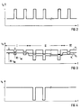
- FIG. 2 shows the current profile on the infrared light emitting diode of the transmitter S; this current is composed of a DC component I DC for the DC test light signal and an AC component I AC for the AC switching signal.
- the amplitude of the received alternating switching signal u + and the equal test light signal u - increase due to the reflection; if the amplitude of the reflected alternating switching signal u + exceeds the amplitude of the direct test light signal u - which is predetermined as the threshold value for the comparator K - , the comparator K switches - as can be seen from the voltage profile u K at the output of the comparator according to FIG. 6.
- the AC amplitude of the transmitter current is expediently set so that, taking into account the transmitter S with the lowest beam strength and the receiver E with the lowest sensitivity when a button is pressed, a signal is clearly recognized; then the DC amplitude of the direct-probe light and - to increase the extent that an internal reflection (scattered light) is suppressed and the comparator K with no actuation, that is contact of the key element T1-T6, not switches.
- FIG. 7 shows as an example different scatter ranges of six key elements each for the ON signal level or the OFF signal level resulting therefrom at a distance a1-a6 in the form of analog voltage amplitudes of the pulsed signals when the six key elements T1-T6 one are actuated or not actuated Hob control.
Landscapes
- Chemical & Material Sciences (AREA)
- Engineering & Computer Science (AREA)
- Ceramic Engineering (AREA)
- Physics & Mathematics (AREA)
- Nonlinear Science (AREA)
- Electronic Switches (AREA)
- Optical Recording Or Reproduction (AREA)
Applications Claiming Priority (2)
| Application Number | Priority Date | Filing Date | Title |
|---|---|---|---|
| DE1995147301 DE19547301C1 (de) | 1995-12-18 | 1995-12-18 | Betätigungsvorrichtung mit zumindest einem optoelektronischen Tastenelement |
| DE19547301 | 1995-12-18 |
Publications (2)
| Publication Number | Publication Date |
|---|---|
| EP0780979A2 true EP0780979A2 (fr) | 1997-06-25 |
| EP0780979A3 EP0780979A3 (fr) | 1998-03-11 |
Family
ID=7780485
Family Applications (1)
| Application Number | Title | Priority Date | Filing Date |
|---|---|---|---|
| EP96119572A Withdrawn EP0780979A3 (fr) | 1995-12-18 | 1996-12-05 | Dispositif d'actionnement comprenant au moins une touche optoélectronique |
Country Status (2)
| Country | Link |
|---|---|
| EP (1) | EP0780979A3 (fr) |
| DE (1) | DE19547301C1 (fr) |
Families Citing this family (4)
| Publication number | Priority date | Publication date | Assignee | Title |
|---|---|---|---|---|
| DE10122023A1 (de) * | 2001-05-07 | 2002-11-21 | Infineon Technologies Ag | Anordnung und Verfahren zur Ermittlung des jeweils aktuellen Pegels eines digitalen Signals |
| DE10214198B4 (de) * | 2002-03-29 | 2005-07-07 | Münchner Hybrid Systemtechnik GmbH | Schaltbares Leuchtmittel mit automatischer Notbeleuchtung |
| DE10214199B4 (de) * | 2002-03-29 | 2005-07-14 | Münchner Hybrid Systemtechnik GmbH | Beleuchtbarer sensitiver Schalter |
| DE102020110275A1 (de) | 2020-04-15 | 2021-10-21 | Münchner Hybrid Systemtechnik GmbH | Innenbeleuchtungssystem und Möbelstück |
Citations (2)
| Publication number | Priority date | Publication date | Assignee | Title |
|---|---|---|---|---|
| WO1986001953A1 (fr) * | 1984-09-22 | 1986-03-27 | Michael John Nobbs | Commutateur |
| JPH03274822A (ja) * | 1990-03-24 | 1991-12-05 | Nippondenso Co Ltd | 光学式タッチスイッチ |
Family Cites Families (12)
| Publication number | Priority date | Publication date | Assignee | Title |
|---|---|---|---|---|
| DE2943913A1 (de) * | 1979-10-31 | 1981-05-14 | Sennheiser Electronic Kg, 3002 Wedemark | Verfahren zum empfang impulsfoermiger lichtsignale |
| US4743856A (en) * | 1983-09-26 | 1988-05-10 | Simulaser Corporation | Digital optical receiver circuit |
| DE3408261A1 (de) * | 1984-03-07 | 1985-09-19 | Hansa Metallwerke Ag, 7000 Stuttgart | Annaeherungsschalter sowie steuerschaltungsanordnung hierfuer |
| DE3601516A1 (de) * | 1986-01-20 | 1987-07-23 | Agie Ag Ind Elektronik | Lichtschranke |
| DE3733656C1 (de) * | 1987-10-05 | 1989-02-02 | Hoermann Kg | Reflexionslichtschranke |
| JPH0381686A (ja) * | 1989-08-25 | 1991-04-08 | Hitachi Ltd | 反射型人体検出回路 |
| DE9010998U1 (de) * | 1990-03-01 | 1990-10-25 | Sartorius AG, 3400 Göttingen | Komparatorschaltung für Signale einer Lichtschranke |
| JPH03266002A (ja) * | 1990-03-16 | 1991-11-27 | Nec Yamagata Ltd | 無人搬送台車 |
| DE4016316B4 (de) * | 1990-05-21 | 2004-02-12 | Robert Bosch Gmbh | Auswerteschaltung für die Signale einer Signalquelle |
| DE4102152A1 (de) * | 1991-01-25 | 1992-07-30 | Lamarche Jean Luc | Optoelektronischer sensor |
| DE4207772C3 (de) * | 1992-03-11 | 1999-01-21 | Cherry Mikroschalter Gmbh | Sensorschalter mit Größenerkennung |
| JP3401800B2 (ja) * | 1992-05-01 | 2003-04-28 | オムロン株式会社 | 光電スイッチ |
-
1995
- 1995-12-18 DE DE1995147301 patent/DE19547301C1/de not_active Expired - Fee Related
-
1996
- 1996-12-05 EP EP96119572A patent/EP0780979A3/fr not_active Withdrawn
Patent Citations (2)
| Publication number | Priority date | Publication date | Assignee | Title |
|---|---|---|---|---|
| WO1986001953A1 (fr) * | 1984-09-22 | 1986-03-27 | Michael John Nobbs | Commutateur |
| JPH03274822A (ja) * | 1990-03-24 | 1991-12-05 | Nippondenso Co Ltd | 光学式タッチスイッチ |
Non-Patent Citations (1)
| Title |
|---|
| PATENT ABSTRACTS OF JAPAN vol. 16, no. 95 (E - 1175) 9 March 1992 (1992-03-09) * |
Also Published As
| Publication number | Publication date |
|---|---|
| EP0780979A3 (fr) | 1998-03-11 |
| DE19547301C1 (de) | 1997-03-13 |
Similar Documents
| Publication | Publication Date | Title |
|---|---|---|
| DE4207772C2 (de) | Sensorschalter mit Größenerkennung | |
| DE3038102C2 (de) | Elektronisches, berührungslos arbeitendes Schaltgerät | |
| EP1269629A1 (fr) | Commutateur optoelectronique a evaluation des variations de mouvement | |
| WO2003030363A2 (fr) | Circuit pourvu d'une unite d'indication optoelectronique | |
| AT403975B (de) | Annäherungsschalter sowie steuerschaltungsanordnung hierfür | |
| DE2821681A1 (de) | Lichtschrankensystem | |
| EP0418989A2 (fr) | Barrière de lumière | |
| EP1729417A2 (fr) | Commutateur à touche tactile | |
| WO2013113695A1 (fr) | Procédé de fonctionnement d'un capteur d'approche optoélectronique et capteur d'approche optoélectronique | |
| DE19537615B4 (de) | Verfahren zum Betrieb eines optischen Lichttasters | |
| DE19547301C1 (de) | Betätigungsvorrichtung mit zumindest einem optoelektronischen Tastenelement | |
| WO2015011094A1 (fr) | Procédé de fonctionnement d'un capteur de proximité optoélectronique | |
| DE19745493A1 (de) | Näherungssensor und Verfahren zur Personenerkennung | |
| EP0780981B1 (fr) | Circuit d'évaluation pour un capteur à effleurement | |
| EP0039799B1 (fr) | Dispositif pour détecter des mouvements | |
| EP0759660B1 (fr) | Dispositif d'entrée de données pour un transducteur de mesure | |
| DE19547300C1 (de) | Betätigungsvorrichtung mit zumindest einem optoelektronischen Tastenelement | |
| DE19747248A1 (de) | Reflexionslichtschranke | |
| DE19540835C1 (de) | Verfahren zur Umwandlung von, insbesondere zueinander amplitudendifferenten, EIN/AUS-Analogsignalen in entsprechende EIN/AUS-Digitalsignale | |
| DE4337518C1 (de) | Verfahren zur Überwachung eines elektronischen Schaltgerätes | |
| DE19917487A1 (de) | Optoelektronische Vorrichtung | |
| DE29712427U1 (de) | Einschalteindeutigkeit für Kochfelder | |
| EP1349436A2 (fr) | Dispositif d'éclairage commutable avec lumière auxiliaire | |
| EP3361282B1 (fr) | Capteur optique avec circuit limiteur | |
| DE19956055C2 (de) | Verfahren zum Betrieb eines optoelektronischen Näherungsschalters |
Legal Events
| Date | Code | Title | Description |
|---|---|---|---|
| PUAI | Public reference made under article 153(3) epc to a published international application that has entered the european phase |
Free format text: ORIGINAL CODE: 0009012 |
|
| AK | Designated contracting states |
Kind code of ref document: A2 Designated state(s): DE FR GB IT |
|
| PUAL | Search report despatched |
Free format text: ORIGINAL CODE: 0009013 |
|
| AK | Designated contracting states |
Kind code of ref document: A3 Designated state(s): DE FR GB IT |
|
| 17P | Request for examination filed |
Effective date: 19980908 |
|
| RAP1 | Party data changed (applicant data changed or rights of an application transferred) |
Owner name: BSH BOSCH UND SIEMENS HAUSGERAETE GMBH |
|
| 17Q | First examination report despatched |
Effective date: 19990824 |
|
| STAA | Information on the status of an ep patent application or granted ep patent |
Free format text: STATUS: THE APPLICATION HAS BEEN WITHDRAWN |
|
| 18W | Application withdrawn |
Withdrawal date: 20000511 |