EP0780980A2 - Dispositif d'actionnement comprenant au moins une touche optoélectronique - Google Patents
Dispositif d'actionnement comprenant au moins une touche optoélectronique Download PDFInfo
- Publication number
- EP0780980A2 EP0780980A2 EP96119573A EP96119573A EP0780980A2 EP 0780980 A2 EP0780980 A2 EP 0780980A2 EP 96119573 A EP96119573 A EP 96119573A EP 96119573 A EP96119573 A EP 96119573A EP 0780980 A2 EP0780980 A2 EP 0780980A2
- Authority
- EP
- European Patent Office
- Prior art keywords
- signal
- actuating device
- actuating
- key element
- signals
- Prior art date
- Legal status (The legal status is an assumption and is not a legal conclusion. Google has not performed a legal analysis and makes no representation as to the accuracy of the status listed.)
- Withdrawn
Links
- 230000005693 optoelectronics Effects 0.000 title claims description 6
- 230000004888 barrier function Effects 0.000 claims description 9
- 230000011514 reflex Effects 0.000 claims description 9
- 238000001914 filtration Methods 0.000 claims 1
- 230000032683 aging Effects 0.000 description 4
- 238000009434 installation Methods 0.000 description 3
- 238000004519 manufacturing process Methods 0.000 description 3
- 230000005540 biological transmission Effects 0.000 description 2
- 239000000919 ceramic Substances 0.000 description 2
- 238000011156 evaluation Methods 0.000 description 2
- 239000011521 glass Substances 0.000 description 2
- 230000035945 sensitivity Effects 0.000 description 2
- 206010034960 Photophobia Diseases 0.000 description 1
- 239000003990 capacitor Substances 0.000 description 1
- 238000006243 chemical reaction Methods 0.000 description 1
- 238000011109 contamination Methods 0.000 description 1
- 230000001419 dependent effect Effects 0.000 description 1
- 238000001514 detection method Methods 0.000 description 1
- 208000013469 light sensitivity Diseases 0.000 description 1
- 238000000034 method Methods 0.000 description 1
- 230000001681 protective effect Effects 0.000 description 1
- 239000007787 solid Substances 0.000 description 1
Images
Classifications
-
- H—ELECTRICITY
- H03—ELECTRONIC CIRCUITRY
- H03K—PULSE TECHNIQUE
- H03K17/00—Electronic switching or gating, i.e. not by contact-making and –breaking
- H03K17/14—Modifications for compensating variations of physical values, e.g. of temperature
-
- H—ELECTRICITY
- H03—ELECTRONIC CIRCUITRY
- H03K—PULSE TECHNIQUE
- H03K17/00—Electronic switching or gating, i.e. not by contact-making and –breaking
- H03K17/94—Electronic switching or gating, i.e. not by contact-making and –breaking characterised by the way in which the control signals are generated
- H03K17/96—Touch switches
- H03K17/9627—Optical touch switches
- H03K17/9631—Optical touch switches using a light source as part of the switch
-
- H—ELECTRICITY
- H03—ELECTRONIC CIRCUITRY
- H03K—PULSE TECHNIQUE
- H03K2217/00—Indexing scheme related to electronic switching or gating, i.e. not by contact-making or -breaking covered by H03K17/00
- H03K2217/94—Indexing scheme related to electronic switching or gating, i.e. not by contact-making or -breaking covered by H03K17/00 characterised by the way in which the control signal is generated
- H03K2217/9401—Calibration techniques
- H03K2217/94026—Automatic threshold calibration; e.g. threshold automatically adapts to ambient conditions or follows variation of input
Definitions
- the invention relates to an actuating device with at least one optoelectronic key element according to claim 1.
- comparators in particular amplitude decision makers, are usually used, which compare the analog input signals with a fixed ON threshold value or a fixed OFF threshold value and, when these threshold values are reached, pass on the assignment "ON” or "OFF” as a corresponding digital output signal.
- a preferred practical application example can be seen in the operation of an electronic hotplate control, in which an actuating device is assigned a plurality of optoelectronic key elements, in particular in the form of touch-sensitive infrared reflective light barriers protected by a protective surface, which have an ON analog signal in the presence of a minimum reflection and emit an OFF analog signal, which is then used as a digital output signal "ON” or output signal “OFF” to control the hotplates.
- the actuating device responds to the degree of feedback of the rays reflected by the transmitter of the optoelectronic key element on its receiver; since with this principle no fixed switching thresholds have to be set, but always only the ratio of internal scatter reflection without actuation on the one hand and with additional external actuation reflection on the contacting body, e.g. when the button element is actuated by a finger placed on a reflective ceramic plate of an associated hob touch recess , is formed is both initial initialization and subsequent operational readjustment are no longer necessary. Aging or contamination of the transmitter or receiver components affects the transmitter-receiver path in such a way that both the internal scattered light reflection and the external useful light reflection are changed, in particular reduced, in the same ratio.
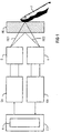
- an electronic controller integrated in the actuation device CO is used to control a transmitter S, in particular an infrared light diode (IR-LED) operating in pulsed mode, in pulses by means of a transmitter control SA.
- the light pulses from the transmitter S hit a glass surface RE, in particular the ceramic surface, which is assigned to a hotplate trough, and are used by the latter when the touch sensor is not actuated, essentially only as a scattered light signal RE2 due to an internal reflection to a receiver E, in particular an infrared receiver, with a subsequent receiver circuit EB reflected.
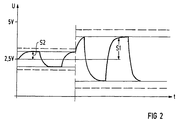
- FIG. 2 shows an example of a signal level S2 when the key element T1-T6 is not actuated or a signal level S1 in the connecting part when the key element T1-T6 is actuated, in each case as an amplitude above a voltage level of 2.5 volts, which is assumed to be zero; the upper and lower boundary lines of the voltage amplitudes of the pulses drawn in a solid contour show a poor transmission path, while the boundary lines drawn above and below in a dashed contour indicate a good transmission path with corresponding external voltage amplitudes.
- an evaluation can then be carried out in a simple manner and independently of tolerances in the actuating device CO as to whether the key element is pressed and thus brought into the ON position or unpressed and is thus in the OFF position. be taken over.
- the comparator K provided for this comparison in the actuation direction CO is expediently designed as a measured value conversion for emitting a corresponding digital ON / OFF signal in the case of analog actuation signals RE1 + RE2 on the input side or in the case of analog scattered light signals RE2 on the input side; advantageously, the comparator K is at the same time such that a e.g. constant light originating from an external light source is filtered out.
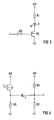
- the transmitter essentially consists of a transmitter S in the form of an IR transmitter diode and a control unit in which the current strength for the IR transmitter diode is fed and can be adjusted via a resistor R1 which is connected in series therewith.
- a switching transistor TR connected in series with the IR transmitter diode S and connected with a series resistor R2 is actuated by the actuating device CO with a square-wave signal, so that the transmitter S emits a direct current-free, pulsed light beam onto the glass pane RE.
- FIG. 4 shows an advantageous receiving device for receiving the analog signal of a reflected scattered light signal RE2 or additional useful light signal RE1.
- an IR phototransistor with an infrared light-sensitive resistor is provided as the receiver E, which changes the potential at its emitter between a voltage of 0 volts and approximately a maximum voltage of 5 volts, depending on the strength of the reflected light.
- the light sensitivity of the receiver E can be set via a resistor R5 which is connected in series with the receiver E.
- the emitter output and thus the connection to the resistor R5 is connected via a voltage divider R3 / R4 in such a way that the analog input of the receiving device and its signal processing comparator K of the actuating device CO to a reference voltage of approximately 2.5 volts, ie to the center of the analog / Digital change area is laid.
- a high-pass filter is formed by the voltage divider R3 / R4 in conjunction with a capacitor C provided between the latter and the emitter of the receiver E in such a way that a disturbing constant light component, which, for example, comes from an ambient light of an extractor hood above the touch well of a hotplate controller, is suppressed.
- the light pulses coming from the transmitter S which reach the receiver E via reflection, are passed through in this high-pass filter and are available to the comparator K of the actuating device CO for further evaluation in the aforementioned sense.
- the sensitivity of the receiving device according to FIG. 4 is expediently to be set with the variable resistor R5 so that the scattered light signal RE2 or S2 has a sufficient amplitude on the one hand, but no overdriving takes place when a key is pressed and thus the actuation signal RE1 + RE2 or S1 received by the receiver E. .
- the signal ratio is from S1 to S2, i.e. of the actuated key element compared to the unactuated key element, for example by a factor of 3
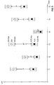
- FIG. 5 shows the tolerance ranges for each of the ON signal levels or the OFF signal levels assumed at intervals a1-a6 in the form of analog voltage amplitudes of the pulsed signals when six button elements T1-T6 of a hotplate control are actuated or not actuated.
Landscapes
- Electronic Switches (AREA)
Applications Claiming Priority (2)
| Application Number | Priority Date | Filing Date | Title |
|---|---|---|---|
| DE1995147300 DE19547300C1 (de) | 1995-12-18 | 1995-12-18 | Betätigungsvorrichtung mit zumindest einem optoelektronischen Tastenelement |
| DE19547300 | 1995-12-18 |
Publications (2)
| Publication Number | Publication Date |
|---|---|
| EP0780980A2 true EP0780980A2 (fr) | 1997-06-25 |
| EP0780980A3 EP0780980A3 (fr) | 1998-03-11 |
Family
ID=7780484
Family Applications (1)
| Application Number | Title | Priority Date | Filing Date |
|---|---|---|---|
| EP96119573A Withdrawn EP0780980A3 (fr) | 1995-12-18 | 1996-12-05 | Dispositif d'actionnement comprenant au moins une touche optoélectronique |
Country Status (2)
| Country | Link |
|---|---|
| EP (1) | EP0780980A3 (fr) |
| DE (1) | DE19547300C1 (fr) |
Cited By (1)
| Publication number | Priority date | Publication date | Assignee | Title |
|---|---|---|---|---|
| DE19805959A1 (de) * | 1998-02-13 | 1999-08-19 | Ego Elektro Geraetebau Gmbh | Sensor-Schaltvorrichtung mit einer Sensortaste |
Families Citing this family (2)
| Publication number | Priority date | Publication date | Assignee | Title |
|---|---|---|---|---|
| DE102010050096B4 (de) * | 2010-10-26 | 2012-08-30 | Michael Hankel | Auswerteschaltung für einen optischen Berührungssensor |
| CN106416075B (zh) | 2014-05-29 | 2019-08-06 | 高准公司 | 自适应反射光触摸传感器 |
Family Cites Families (11)
| Publication number | Priority date | Publication date | Assignee | Title |
|---|---|---|---|---|
| DE2943913A1 (de) * | 1979-10-31 | 1981-05-14 | Sennheiser Electronic Kg, 3002 Wedemark | Verfahren zum empfang impulsfoermiger lichtsignale |
| DE3408261A1 (de) * | 1984-03-07 | 1985-09-19 | Hansa Metallwerke Ag, 7000 Stuttgart | Annaeherungsschalter sowie steuerschaltungsanordnung hierfuer |
| DE3526992A1 (de) * | 1985-07-27 | 1987-02-05 | Weiss Hans Dipl Ing Fh | Einrichtung zum ein- und ausschalten eines elektrischen verbrauchers sowie verwendung einer solchen |
| FR2597682A1 (fr) * | 1986-04-21 | 1987-10-23 | Ferco Int Usine Ferrures | Clavier pour appareil electrique. |
| JPH0381686A (ja) * | 1989-08-25 | 1991-04-08 | Hitachi Ltd | 反射型人体検出回路 |
| DE3931038A1 (de) * | 1989-09-16 | 1991-03-28 | Ottleben Bernd | Lichtschranke |
| DE9010998U1 (de) * | 1990-03-01 | 1990-10-25 | Sartorius AG, 3400 Göttingen | Komparatorschaltung für Signale einer Lichtschranke |
| DE4102152A1 (de) * | 1991-01-25 | 1992-07-30 | Lamarche Jean Luc | Optoelektronischer sensor |
| FR2686147A1 (fr) * | 1992-01-09 | 1993-07-16 | Dietrich Europ Electromenager | Detecteur a touche optique pour la commande d'un des foyers d'une table de cuisson dite vitro-ceramique. |
| DE4207772C3 (de) * | 1992-03-11 | 1999-01-21 | Cherry Mikroschalter Gmbh | Sensorschalter mit Größenerkennung |
| DE4336669C1 (de) * | 1993-10-27 | 1994-12-15 | Ziegler Horst | Eingabefeld |
-
1995
- 1995-12-18 DE DE1995147300 patent/DE19547300C1/de not_active Revoked
-
1996
- 1996-12-05 EP EP96119573A patent/EP0780980A3/fr not_active Withdrawn
Non-Patent Citations (1)
| Title |
|---|
| None |
Cited By (1)
| Publication number | Priority date | Publication date | Assignee | Title |
|---|---|---|---|---|
| DE19805959A1 (de) * | 1998-02-13 | 1999-08-19 | Ego Elektro Geraetebau Gmbh | Sensor-Schaltvorrichtung mit einer Sensortaste |
Also Published As
| Publication number | Publication date |
|---|---|
| DE19547300C1 (de) | 1997-03-06 |
| EP0780980A3 (fr) | 1998-03-11 |
Similar Documents
| Publication | Publication Date | Title |
|---|---|---|
| DE4207772C2 (de) | Sensorschalter mit Größenerkennung | |
| DE3038102C2 (de) | Elektronisches, berührungslos arbeitendes Schaltgerät | |
| EP0443141B1 (fr) | Arrangement de couplage pour commander un ventilateur | |
| WO2003030363A2 (fr) | Circuit pourvu d'une unite d'indication optoelectronique | |
| WO2009049812A1 (fr) | Unité de commande et procédé pour déclencher une fonction | |
| DE3146152A1 (de) | Optoelektrisches tastenfeld | |
| EP1428171A2 (fr) | Dispositif d'utilisation | |
| AT403975B (de) | Annäherungsschalter sowie steuerschaltungsanordnung hierfür | |
| DE2821681A1 (de) | Lichtschrankensystem | |
| EP1001226A2 (fr) | Capteur à ultrasons pour hotte aspiratrice de buée | |
| DE10208469A1 (de) | Elektrisches Gerät, insbesondere Dunstabzugshaube | |
| DE102013200457A1 (de) | Bedienvorrichtung für ein Kraftfahrzeug mit einer Gestenüberwachungseinheit | |
| WO2017001112A1 (fr) | Dispositif de détection optique avec capteurs capacitifs supplémentaires | |
| DE19547300C1 (de) | Betätigungsvorrichtung mit zumindest einem optoelektronischen Tastenelement | |
| EP0994796A1 (fr) | Dispositif et procede permettant de faire fonctionner un detecteur de pluie | |
| WO2002059829A1 (fr) | Dispositif de saisie et procede de saisie d'informations dans une unite de commande | |
| DE19540835C1 (de) | Verfahren zur Umwandlung von, insbesondere zueinander amplitudendifferenten, EIN/AUS-Analogsignalen in entsprechende EIN/AUS-Digitalsignale | |
| DE19917487B4 (de) | Optoelektronische Vorrichtung | |
| DE102016117289A1 (de) | Feldgerät mit einem optoelektronischen Bedienelement sowie Verfahren zur Detektion einer Berührung an dem Bedienelement | |
| EP1049945B1 (fr) | Procédé de mesure de distance et dispositif pour la mise en oeuvre du procédé | |
| EP0039799B1 (fr) | Dispositif pour détecter des mouvements | |
| DE3526992C2 (fr) | ||
| DE19547301C1 (de) | Betätigungsvorrichtung mit zumindest einem optoelektronischen Tastenelement | |
| EP0780981B1 (fr) | Circuit d'évaluation pour un capteur à effleurement | |
| DE29712427U1 (de) | Einschalteindeutigkeit für Kochfelder |
Legal Events
| Date | Code | Title | Description |
|---|---|---|---|
| PUAI | Public reference made under article 153(3) epc to a published international application that has entered the european phase |
Free format text: ORIGINAL CODE: 0009012 |
|
| AK | Designated contracting states |
Kind code of ref document: A2 Designated state(s): DE FR GB IT |
|
| PUAL | Search report despatched |
Free format text: ORIGINAL CODE: 0009013 |
|
| AK | Designated contracting states |
Kind code of ref document: A3 Designated state(s): DE FR GB IT |
|
| 17P | Request for examination filed |
Effective date: 19980908 |
|
| RAP1 | Party data changed (applicant data changed or rights of an application transferred) |
Owner name: BSH BOSCH UND SIEMENS HAUSGERAETE GMBH |
|
| 17Q | First examination report despatched |
Effective date: 19990825 |
|
| STAA | Information on the status of an ep patent application or granted ep patent |
Free format text: STATUS: THE APPLICATION HAS BEEN WITHDRAWN |
|
| 18W | Application withdrawn |
Withdrawal date: 20000511 |