EP0781375B1 - Procede de commande d'un moteur a combustion interne a injection directe - Google Patents
Procede de commande d'un moteur a combustion interne a injection directe Download PDFInfo
- Publication number
- EP0781375B1 EP0781375B1 EP95932016A EP95932016A EP0781375B1 EP 0781375 B1 EP0781375 B1 EP 0781375B1 EP 95932016 A EP95932016 A EP 95932016A EP 95932016 A EP95932016 A EP 95932016A EP 0781375 B1 EP0781375 B1 EP 0781375B1
- Authority
- EP
- European Patent Office
- Prior art keywords
- degree
- depression
- pressure
- engine
- speed
- Prior art date
- Legal status (The legal status is an assumption and is not a legal conclusion. Google has not performed a legal analysis and makes no representation as to the accuracy of the status listed.)
- Expired - Lifetime
Links
Images

Classifications
-
- F—MECHANICAL ENGINEERING; LIGHTING; HEATING; WEAPONS; BLASTING
- F02—COMBUSTION ENGINES; HOT-GAS OR COMBUSTION-PRODUCT ENGINE PLANTS
- F02D—CONTROLLING COMBUSTION ENGINES
- F02D41/00—Electrical control of supply of combustible mixture or its constituents
- F02D41/24—Electrical control of supply of combustible mixture or its constituents characterised by the use of digital means
- F02D41/2406—Electrical control of supply of combustible mixture or its constituents characterised by the use of digital means using essentially read only memories
-
- F—MECHANICAL ENGINEERING; LIGHTING; HEATING; WEAPONS; BLASTING
- F02—COMBUSTION ENGINES; HOT-GAS OR COMBUSTION-PRODUCT ENGINE PLANTS
- F02D—CONTROLLING COMBUSTION ENGINES
- F02D43/00—Conjoint electrical control of two or more functions, e.g. ignition, fuel-air mixture, recirculation, supercharging or exhaust-gas treatment
-
- F—MECHANICAL ENGINEERING; LIGHTING; HEATING; WEAPONS; BLASTING
- F02—COMBUSTION ENGINES; HOT-GAS OR COMBUSTION-PRODUCT ENGINE PLANTS
- F02D—CONTROLLING COMBUSTION ENGINES
- F02D41/00—Electrical control of supply of combustible mixture or its constituents
- F02D41/0002—Controlling intake air
-
- F—MECHANICAL ENGINEERING; LIGHTING; HEATING; WEAPONS; BLASTING
- F02—COMBUSTION ENGINES; HOT-GAS OR COMBUSTION-PRODUCT ENGINE PLANTS
- F02D—CONTROLLING COMBUSTION ENGINES
- F02D41/00—Electrical control of supply of combustible mixture or its constituents
- F02D41/30—Controlling fuel injection
- F02D41/38—Controlling fuel injection of the high pressure type
-
- F—MECHANICAL ENGINEERING; LIGHTING; HEATING; WEAPONS; BLASTING
- F02—COMBUSTION ENGINES; HOT-GAS OR COMBUSTION-PRODUCT ENGINE PLANTS
- F02B—INTERNAL-COMBUSTION PISTON ENGINES; COMBUSTION ENGINES IN GENERAL
- F02B75/00—Other engines
- F02B75/02—Engines characterised by their cycles, e.g. six-stroke
- F02B2075/022—Engines characterised by their cycles, e.g. six-stroke having less than six strokes per cycle
- F02B2075/025—Engines characterised by their cycles, e.g. six-stroke having less than six strokes per cycle two
-
- F—MECHANICAL ENGINEERING; LIGHTING; HEATING; WEAPONS; BLASTING
- F02—COMBUSTION ENGINES; HOT-GAS OR COMBUSTION-PRODUCT ENGINE PLANTS
- F02B—INTERNAL-COMBUSTION PISTON ENGINES; COMBUSTION ENGINES IN GENERAL
- F02B2275/00—Other engines, components or details, not provided for in other groups of this subclass
- F02B2275/14—Direct injection into combustion chamber
-
- F—MECHANICAL ENGINEERING; LIGHTING; HEATING; WEAPONS; BLASTING
- F02—COMBUSTION ENGINES; HOT-GAS OR COMBUSTION-PRODUCT ENGINE PLANTS
- F02D—CONTROLLING COMBUSTION ENGINES
- F02D41/00—Electrical control of supply of combustible mixture or its constituents
- F02D41/30—Controlling fuel injection
- F02D41/38—Controlling fuel injection of the high pressure type
- F02D2041/389—Controlling fuel injection of the high pressure type for injecting directly into the cylinder
-
- F—MECHANICAL ENGINEERING; LIGHTING; HEATING; WEAPONS; BLASTING
- F02—COMBUSTION ENGINES; HOT-GAS OR COMBUSTION-PRODUCT ENGINE PLANTS
- F02D—CONTROLLING COMBUSTION ENGINES
- F02D2200/00—Input parameters for engine control
- F02D2200/02—Input parameters for engine control the parameters being related to the engine
- F02D2200/04—Engine intake system parameters
- F02D2200/0406—Intake manifold pressure
-
- F—MECHANICAL ENGINEERING; LIGHTING; HEATING; WEAPONS; BLASTING
- F02—COMBUSTION ENGINES; HOT-GAS OR COMBUSTION-PRODUCT ENGINE PLANTS
- F02D—CONTROLLING COMBUSTION ENGINES
- F02D2400/00—Control systems adapted for specific engine types; Special features of engine control systems not otherwise provided for; Power supply, connectors or cabling for engine control systems
- F02D2400/04—Two-stroke combustion engines with electronic control
-
- Y—GENERAL TAGGING OF NEW TECHNOLOGICAL DEVELOPMENTS; GENERAL TAGGING OF CROSS-SECTIONAL TECHNOLOGIES SPANNING OVER SEVERAL SECTIONS OF THE IPC; TECHNICAL SUBJECTS COVERED BY FORMER USPC CROSS-REFERENCE ART COLLECTIONS [XRACs] AND DIGESTS
- Y02—TECHNOLOGIES OR APPLICATIONS FOR MITIGATION OR ADAPTATION AGAINST CLIMATE CHANGE
- Y02T—CLIMATE CHANGE MITIGATION TECHNOLOGIES RELATED TO TRANSPORTATION
- Y02T10/00—Road transport of goods or passengers
- Y02T10/10—Internal combustion engine [ICE] based vehicles
- Y02T10/12—Improving ICE efficiencies
-
- Y—GENERAL TAGGING OF NEW TECHNOLOGICAL DEVELOPMENTS; GENERAL TAGGING OF CROSS-SECTIONAL TECHNOLOGIES SPANNING OVER SEVERAL SECTIONS OF THE IPC; TECHNICAL SUBJECTS COVERED BY FORMER USPC CROSS-REFERENCE ART COLLECTIONS [XRACs] AND DIGESTS
- Y02—TECHNOLOGIES OR APPLICATIONS FOR MITIGATION OR ADAPTATION AGAINST CLIMATE CHANGE
- Y02T—CLIMATE CHANGE MITIGATION TECHNOLOGIES RELATED TO TRANSPORTATION
- Y02T10/00—Road transport of goods or passengers
- Y02T10/10—Internal combustion engine [ICE] based vehicles
- Y02T10/40—Engine management systems
Definitions
- the present invention relates to a method for controlling a combustion engine internal, more particularly suitable for a direct injection engine, two or four time.
- the present invention therefore aims to overcome these drawbacks of prior art systems taking into account the evolution of the filling in engine air without sacrificing the benefits of these systems for control of direct injection engines.
- a first mode of execution of the method it is determined in the table, from the speed and degree of penetration measured, a setpoint of the pressure / temperature ratio of the intake air, and we act on the opening angle of a throttle valve placed in the intake manifold to control the gear pressure / temperature measured at this setpoint.
- a second mode of execution of the method it is determined by reading reverse of the table, from the speed and pressure / temperature ratio measured a degree of virtual depressing of the accelerator pedal, and this degree is used virtual depressing of the pedal to provide at least one of the adjustment parameters optimal motor.
- the reading of the degree of virtual depression of the pedal in the table is determined by determining for the tabulated regimes immediately adjacent to the actual regime, the value of the degree depression of the pedal corresponding to the pressure / temperature ratio measured, and by interpolating between these values according to the real regime.
- the degree of virtual penetration correspond to the pressure / temperature ratio measured, only the degree of virtual penetration closest to the actual degree of penetration of the pedal is taken into consideration.
- the degree of virtual penetration is determined by choosing the actual degree of penetration if this is between the two values of the degree of depression limiting the interval or the nearest limit value otherwise.
- the engine intake manifold 10 includes a motorized intake throttle 9 for adjusting the amount of air admitted into the engine.
- the computer 11 also receives a signal PP representative of the depressing of an accelerator pedal 4, a signal representative of the speed N of the engine delivered by a speed sensor 5, as well as a signal representative of the temperature Te of the liquid cooling, delivered by a sensor 6.
- the computer 11 generates control signals on the basis of these signals and according to programmed strategies.
- the computer delivers to fuel supply means, for example an injector 7, a signal representative of the quantity of fuel to be injected into the engine, this signal defining for example the phase ⁇ i and the duration Ti of fuel injection.
- the computer also controls the motorized intake throttle valve 9 placed in the intake duct 10, by means of a signal defining an angle ⁇ P of opening of the throttle valve, as well as ignition means 8 by an All signal.
- FIG. 2 represents the functional architecture of the computer 11.
- tables have been developed giving the optimal values of the engine control parameters such as the throttle opening angle ⁇ P, the duration Ti and the fuel injection phase ⁇ i, the ignition time, depending on the degree of depressing PP of the accelerator pedal and the speed N. These optimal values are obtained in stabilized operation, that is to say for constant values of PP and N, by adjusting the control parameters to obtain, for example, the best compromise between engine torque and pollution.
- the temperature T col and the pressure P col of the air prevailing in the intake manifold were also measured when these optimal values are applied to the engine and a table of the pressure / temperature R PT0 as a function of the degree of depressing PP of the accelerator pedal and of the speed N.
- the computer 11 comprises a block 12 receiving the signals T col and P col representative of the temperature and of the prevailing air pressure in the intake manifold 10 and capable of forming the pressure / temperature ratio measured R PTm .
- the computer 11 also includes a block 13 comprising a table of pressure / temperature ratios established as described above.
- the computer 11 further comprises blocks 14 and 15 used to determine the angle ⁇ P of opening of the throttle valve 9 the operation of which will be explained in relation to a first mode of operation of the method according to the invention, and blocks 16 and 17 respectively providing the optimal fuel injection and ignition parameters, the operation of which will be explained in relation to a second mode of operation of the method according to the invention.
- the computer 11 receives the signals PP, N, T col and P col representative respectively of the degree of depressing of the pedal, of the engine speed, of the temperature and of the air pressure in the manifold. admission.
- the degree of depressing of the pedal PP and the speed N are transmitted to block 14 which develops a nominal opening value of the throttle 9 by means of the table drawn up during the focus.
- These same signals PP and N are transmitted to block 13 which, by direct reading of the table of reports R PT0 which it contains, supplies to block 15 a reference value R PTc corresponding to the value of the pressure / temperature ratio of the air prevailing in the intake manifold, under the same conditions, during the tests.
- the block 15 simultaneously receives a value R PTm of the pressure / temperature ratio of the air measured in the intake manifold, developed by the block 12 on the basis of the signals T col and P col supplied by the sensors 2 and 3.
- the block 15 behaves as a standard regulator, of the PID type for example and provides a correction of the throttle opening angle at the output which is added to the nominal opening value delivered by block 14 to form the ⁇ P d command opening of the throttle valve 9.
- a servo-control is thus produced which tends to correct the nominal value of the throttle valve opening determined under the experimental conditions of development to take account of the variations in air filling linked to dispersions of permeability of the intake assembly between the engines, the differences between experimental and real conditions as well as the aging of the system.
- the computer 11 receives the signals PP, N, T col and P col representative respectively of the degree of depressing of the pedal, the engine speed, the temperature and the air pressure in the intake manifold. From these last two signals, block 12 develops the measured pressure / temperature ratio R PTm which is transmitted to block 13. The latter also receives the engine speed N. Block 13 then performs an "inverse" reading of the table of pressure / temperature ratios it contains and determines from the signals R PTm and N a degree of virtual depression PPV of the accelerator pedal corresponding to the degree of depression which, during the development of the engine, made it possible to obtain a pressure / temperature ratio equal to R PTm at the measured speed N.
- the degree of virtual depression PPV thus determined does not necessarily correspond to the degree of real depression PP.
- the air filling delay related to the capacity of the intake manifold causes a delay in the degree of virtual depression PPV compared to the degree of depression measured PP.
- the degree of virtual depression PPV thus determined is transmitted, together with the regime N to block 16 for defining the injection duration Ti.
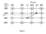
- FIG. 3 shows a fragment of the table contained in block 13, which extends from 1000 to 2500 revolutions per minute in engine speed (columns) and from 10% to 40% of the maximum degree of depression of the accelerator pedal (lines).
- the values of the pressure / temperature ratio appearing in the table are expressed in Pascal per Kelvin degree.
- the same operation is carried out for 2000 rpm and a virtual degree of penetration of 27.5% is obtained.
- the two modes of operation of the process which have been described above are not mutually exclusive. They can be used jointly or separately for controlling direct injection engines.
- the invention is not not limited to controlling the parameters described, many other parameters, depending on the type and complexity of the motor ordered can be treated in this way, like for example the degassing control of a filter intended to capture the vapors fuel, etc.
- the method according to the invention can also be extended to the combination with corrections known in themselves, such as for example the correction of commands issued (duration and phase of injection, ignition command, etc.), dependent on other input parameters such as the temperature of the Te cooling provided by a sensor 6 or the presence of rattling.
Landscapes
- Engineering & Computer Science (AREA)
- Chemical & Material Sciences (AREA)
- Combustion & Propulsion (AREA)
- Mechanical Engineering (AREA)
- General Engineering & Computer Science (AREA)
- Electrical Control Of Air Or Fuel Supplied To Internal-Combustion Engine (AREA)
- Control Of Throttle Valves Provided In The Intake System Or In The Exhaust System (AREA)
- Combined Controls Of Internal Combustion Engines (AREA)
Abstract
Description
- la figure 1 représente le schéma d'un moteur équipé d'un dispositif adapté à la mise en oeuvre du procédé de commande selon l'invention,
- la figure 2 représente un schéma de l'architecture fonctionnelle d'un calculateur faisant partie du dispositif de la figure 1, et
- la figure 3 représente un schéma utile à la compréhension d'une étape du procédé selon l'invention.
Claims (6)
- Procédé de commande d'un moteur à combustion inteme (1) à injection directe, du type utilisant une mesure du degré d'enfoncement (PP) d'une pédale d'accélérateur (4) et une mesure du régime (N) de rotation du moteur pour fournir des paramètres (Ti; i; All; αP) de réglage optimal dudit moteur, caractérisé en ce que :on établit, lors de la mise au point du moteur, une table représentant pour chaque couple degré d'enfoncement (PP), régime (N), le rapport pression/température (RPT0) de l'air régnant dans le collecteur d'admission en fonctionnement stabilisé,on mesure, en fonctionnement normal, la pression (Pcol) et la température (Tcol) de l'air admis, et on forme le rapport pression / température mesurés (RPTm)on utilise la table et une au moins des mesures effectuées pour en déduire au moins un des paramètres de réglage optimal du moteur.
- Procédé selon la revendication 1, caractérisé en ce que:on détermine dans la table, à partir du régime (N) et du degré d'enfoncement (PP) mesurés une valeur de consigne (RPTc) du rapport pression/température de l'air admis, eton agit sur l'angle d'ouverture (αP) d'un papillon des gaz (9) placé dans le collecteur d'admission pour asservir le rapport pression / température mesuré (RPTm) à cette valeur de consigne.
- Procédé selon la revendication 1, caractérisé en ce que:on détermine par lecture inverse de la table, à partir du régime (N) et du rapport pression/température (RPTm) mesurés un degré d'enfoncement virtuel (PPV) de la pédale d'accélérateur, eton utilise ce degré d'enfoncement virtuel (PPV) de la pédale pour foumir au moins un des paramètres de réglage optimal du moteur.
- Procédé selon la revendication 3, caractérisé en ce que la lecture du degré d'enfoncement virtuel (PPV) de la pédale dans la table s'effectue en déterminant pour les régimes tabulés immédiatement adjacents au régime réel (N), la valeur du degré d'enfoncement de la pédale correspondant au rapport pression / température mesuré, et en interpolant entre ces valeurs en fonction du régime réel.
- Procédé selon la revendication 4, caractérisé en ce que, lorsque plusieurs degrés d'enfoncement virtuel (PPV) correspondent au rapport pression / température mesuré, seul le degré d'enfoncement virtuel le plus proche du degré d'enfoncement réel de la pédale est pris en considération.
- Procédé selon la revendication 4, caractérisé en ce que, lorsque pour un régime tabulé immédiatement adjacent au régime réel (N), la variation du rapport pression/température enregistré dans la table (RPT0) sur un intervalle entre deux valeurs du degré d'enfoncement de la pédale (PP) encadrant la valeur du rapport mesuré (RPTm) est inférieure à un seuil prédéterminé, le degré d'enfoncement virtuel (PPV) est déterminé en choisissant le degré d'enfoncement réel si celui-ci est compris entre les deux valeurs du degré d'enfoncement limitant l'intervalle ou la valeur limite la plus proche dans le cas contraire.
Applications Claiming Priority (3)
| Application Number | Priority Date | Filing Date | Title |
|---|---|---|---|
| FR9410947 | 1994-09-12 | ||
| FR9410947A FR2724417B1 (fr) | 1994-09-12 | 1994-09-12 | Procede de commande d'un moteur a combustion interne a injection directe |
| PCT/EP1995/003544 WO1996008645A1 (fr) | 1994-09-12 | 1995-09-08 | Procede de commande d'un moteur a combustion interne a injection directe |
Publications (2)
| Publication Number | Publication Date |
|---|---|
| EP0781375A1 EP0781375A1 (fr) | 1997-07-02 |
| EP0781375B1 true EP0781375B1 (fr) | 2000-02-02 |
Family
ID=9466920
Family Applications (1)
| Application Number | Title | Priority Date | Filing Date |
|---|---|---|---|
| EP95932016A Expired - Lifetime EP0781375B1 (fr) | 1994-09-12 | 1995-09-08 | Procede de commande d'un moteur a combustion interne a injection directe |
Country Status (8)
| Country | Link |
|---|---|
| US (1) | US5775295A (fr) |
| EP (1) | EP0781375B1 (fr) |
| JP (1) | JP3871709B2 (fr) |
| KR (1) | KR100378480B1 (fr) |
| DE (1) | DE69514929T2 (fr) |
| ES (1) | ES2143072T3 (fr) |
| FR (1) | FR2724417B1 (fr) |
| WO (1) | WO1996008645A1 (fr) |
Families Citing this family (6)
| Publication number | Priority date | Publication date | Assignee | Title |
|---|---|---|---|---|
| JP2000192838A (ja) * | 1998-12-25 | 2000-07-11 | Mitsubishi Electric Corp | 自動車用エンジン制御装置 |
| DE10024269A1 (de) * | 2000-05-17 | 2001-12-20 | Bosch Gmbh Robert | Verfahren und Vorrichtung zur Filterung eines Signals |
| DE10046449A1 (de) * | 2000-09-18 | 2002-03-28 | Daimler Chrysler Ag | Verfahren zur Einstellung eines Saugrohrdruckes bzw. eines Massenliefergrades einer Brennkraftmaschine |
| US7010417B2 (en) * | 2002-12-03 | 2006-03-07 | Cummins, Inc. | System and method for determining maximum available engine torque |
| US8588999B2 (en) | 2010-07-22 | 2013-11-19 | General Electric Company | Method and system for engine emission control |
| CN110529265B (zh) * | 2019-09-05 | 2022-05-13 | 广西玉柴机器股份有限公司 | 柴油机多档位恒定转速的控制方法 |
Family Cites Families (7)
| Publication number | Priority date | Publication date | Assignee | Title |
|---|---|---|---|---|
| US4625690A (en) * | 1984-08-03 | 1986-12-02 | Nissan Motor Company, Limited | System for controlling an engine and method therefor |
| US4799467A (en) * | 1986-07-16 | 1989-01-24 | Honda Giken Kogyo Kabushiki Kaisha | Throttle valve control system for an internal combustion engine |
| FR2657398B1 (fr) * | 1990-01-22 | 1994-06-10 | Renault | Procede de regulation sur vehicule d'un moteur a injection directe et allumage commande et systeme pour la mise en óoeuvre du procede et utilisation pour un moteur deux temps. |
| FR2659114B1 (fr) * | 1990-03-02 | 1994-07-08 | Siemens Automotive Sa | Procede et dispositif de commande de la richesse du melange air/carburant d'alimentation d'un moteur a combustion interne. |
| EP0450787A3 (en) * | 1990-04-04 | 1992-09-09 | Lucas Industries Public Limited Company | Engine control system and method |
| US5150692A (en) * | 1991-12-16 | 1992-09-29 | General Motors Corporation | System for controlling air supply pressure in a pneumatic direct fuel injected internal combustion engine |
| US5526787A (en) * | 1995-05-08 | 1996-06-18 | Ford Motor Company | Electronic throttle control system including mechanism for determining desired throttle position |
-
1994
- 1994-09-12 FR FR9410947A patent/FR2724417B1/fr not_active Expired - Fee Related
-
1995
- 1995-09-08 EP EP95932016A patent/EP0781375B1/fr not_active Expired - Lifetime
- 1995-09-08 KR KR1019970701620A patent/KR100378480B1/ko not_active Expired - Fee Related
- 1995-09-08 US US08/809,659 patent/US5775295A/en not_active Expired - Lifetime
- 1995-09-08 ES ES95932016T patent/ES2143072T3/es not_active Expired - Lifetime
- 1995-09-08 WO PCT/EP1995/003544 patent/WO1996008645A1/fr not_active Ceased
- 1995-09-08 DE DE69514929T patent/DE69514929T2/de not_active Expired - Fee Related
- 1995-09-08 JP JP50988596A patent/JP3871709B2/ja not_active Expired - Fee Related
Also Published As
| Publication number | Publication date |
|---|---|
| FR2724417B1 (fr) | 1996-10-18 |
| WO1996008645A1 (fr) | 1996-03-21 |
| DE69514929D1 (de) | 2000-03-09 |
| JPH10505646A (ja) | 1998-06-02 |
| US5775295A (en) | 1998-07-07 |
| ES2143072T3 (es) | 2000-05-01 |
| JP3871709B2 (ja) | 2007-01-24 |
| KR100378480B1 (ko) | 2003-06-18 |
| KR970706451A (ko) | 1997-11-03 |
| EP0781375A1 (fr) | 1997-07-02 |
| FR2724417A1 (fr) | 1996-03-15 |
| DE69514929T2 (de) | 2000-06-21 |
Similar Documents
| Publication | Publication Date | Title |
|---|---|---|
| FR2832459A1 (fr) | Procede et appareil de commande et de regulation pour la mise en oeuvre d'un moteur a combustion interne | |
| CA2048085A1 (fr) | Methode de determination de la pression barometrique entourant un moteur a combustion interne | |
| FR2536121A1 (fr) | Systeme et procede de reglage d'un rapport air-carburant | |
| FR2714697A1 (fr) | Système de régulation de la suralimentation d'un moteur à combustion interne. | |
| JPH09195826A (ja) | 多気筒エンジンの空燃比制御方法 | |
| US5631412A (en) | Apparatus and method for estimating atmospheric pressure in an internal combustion engine | |
| EP0781375B1 (fr) | Procede de commande d'un moteur a combustion interne a injection directe | |
| FR2720787A1 (fr) | Procédé et dispositif de détermination des paramètres spécifiques des injecteurs d'un moteur à combustion, notamment d'un moteur diesel à pré-injection. | |
| EP1590562B1 (fr) | Procede de commande d elements d execution de fonctions elementaires de moteur a combustion interne. | |
| EP0522908B1 (fr) | Procédé et système de calcul de la masse d'air frais dans un cylindre de moteur à combustion interne | |
| FR2849897A1 (fr) | Procede de fonctionnement d'un moteur a combustion interne | |
| EP0264332B1 (fr) | Procédé de correction de la richesse d'un mélange air-carburant admis dans un moteur à combustion interne, à injection électronique | |
| FR2893984A1 (fr) | Procede et dispositif de commande d'un moteur a combustion interne | |
| FR2768460A1 (fr) | Procede de mise en oeuvre d'un moteur a combustion interne | |
| US7798123B2 (en) | Internal combustion engine control device | |
| EP0639704B1 (fr) | Procédé de calcul de la masse d'air admise dans un moteur à combustion interne | |
| FR2858359A1 (fr) | Procede et dispositif de gestion d'une unite d'entrainement comprenant un moteur a combustion interne | |
| EP4048884A1 (fr) | Procédé de régulation d'une pression dans un système d'injection d'eau pour un moteur à combustion interne | |
| FR2857055A1 (fr) | Procede de gestion d'un moteur a combustion interne | |
| FR2894626A1 (fr) | Procede de gestion d'un moteur a combustion interne | |
| EP1065363B1 (fr) | Procédé de contrôle du couple d'un moteur à combustion interne | |
| FR2878575A1 (fr) | Procede de regulation d'un systeme d'admission d'un moteur a combustion interne et vehicule automobile pour la mise en oeuvre du procede | |
| EP1647692A1 (fr) | Procédé de régulation d'un système d'admission d'un moteur à combustion interne et véhicule automobile mettant en oeuvre ce procédé | |
| FR2870887A1 (fr) | Procede de gestion d'un moteur a combustion interne | |
| EP3475556B1 (fr) | Procede de determination de l'avance a l'allumage d'un moteur a combustion interne et procede de controle d'un moteur utilisant un tel procede |
Legal Events
| Date | Code | Title | Description |
|---|---|---|---|
| PUAI | Public reference made under article 153(3) epc to a published international application that has entered the european phase |
Free format text: ORIGINAL CODE: 0009012 |
|
| 17P | Request for examination filed |
Effective date: 19960904 |
|
| AK | Designated contracting states |
Kind code of ref document: A1 Designated state(s): DE ES GB IT |
|
| GRAG | Despatch of communication of intention to grant |
Free format text: ORIGINAL CODE: EPIDOS AGRA |
|
| 17Q | First examination report despatched |
Effective date: 19990226 |
|
| GRAG | Despatch of communication of intention to grant |
Free format text: ORIGINAL CODE: EPIDOS AGRA |
|
| GRAH | Despatch of communication of intention to grant a patent |
Free format text: ORIGINAL CODE: EPIDOS IGRA |
|
| GRAH | Despatch of communication of intention to grant a patent |
Free format text: ORIGINAL CODE: EPIDOS IGRA |
|
| GRAA | (expected) grant |
Free format text: ORIGINAL CODE: 0009210 |
|
| AK | Designated contracting states |
Kind code of ref document: B1 Designated state(s): DE ES GB IT |
|
| GBT | Gb: translation of ep patent filed (gb section 77(6)(a)/1977) |
Effective date: 20000202 |
|
| REF | Corresponds to: |
Ref document number: 69514929 Country of ref document: DE Date of ref document: 20000309 |
|
| ITF | It: translation for a ep patent filed | ||
| REG | Reference to a national code |
Ref country code: ES Ref legal event code: FG2A Ref document number: 2143072 Country of ref document: ES Kind code of ref document: T3 |
|
| PLBE | No opposition filed within time limit |
Free format text: ORIGINAL CODE: 0009261 |
|
| STAA | Information on the status of an ep patent application or granted ep patent |
Free format text: STATUS: NO OPPOSITION FILED WITHIN TIME LIMIT |
|
| 26N | No opposition filed | ||
| REG | Reference to a national code |
Ref country code: GB Ref legal event code: IF02 |
|
| PGFP | Annual fee paid to national office [announced via postgrant information from national office to epo] |
Ref country code: ES Payment date: 20061024 Year of fee payment: 12 |
|
| PGFP | Annual fee paid to national office [announced via postgrant information from national office to epo] |
Ref country code: DE Payment date: 20061120 Year of fee payment: 12 |
|
| PGFP | Annual fee paid to national office [announced via postgrant information from national office to epo] |
Ref country code: GB Payment date: 20070910 Year of fee payment: 13 |
|
| PGFP | Annual fee paid to national office [announced via postgrant information from national office to epo] |
Ref country code: IT Payment date: 20070926 Year of fee payment: 13 |
|
| PG25 | Lapsed in a contracting state [announced via postgrant information from national office to epo] |
Ref country code: DE Free format text: LAPSE BECAUSE OF NON-PAYMENT OF DUE FEES Effective date: 20080401 |
|
| REG | Reference to a national code |
Ref country code: ES Ref legal event code: FD2A Effective date: 20070910 |
|
| PG25 | Lapsed in a contracting state [announced via postgrant information from national office to epo] |
Ref country code: ES Free format text: LAPSE BECAUSE OF NON-PAYMENT OF DUE FEES Effective date: 20070910 |
|
| GBPC | Gb: european patent ceased through non-payment of renewal fee |
Effective date: 20080908 |
|
| PG25 | Lapsed in a contracting state [announced via postgrant information from national office to epo] |
Ref country code: IT Free format text: LAPSE BECAUSE OF NON-PAYMENT OF DUE FEES Effective date: 20080908 |
|
| PG25 | Lapsed in a contracting state [announced via postgrant information from national office to epo] |
Ref country code: GB Free format text: LAPSE BECAUSE OF NON-PAYMENT OF DUE FEES Effective date: 20080908 |