EP0781481B1 - Demodulateur-compensateur aveugle - Google Patents
Demodulateur-compensateur aveugle Download PDFInfo
- Publication number
- EP0781481B1 EP0781481B1 EP95933114A EP95933114A EP0781481B1 EP 0781481 B1 EP0781481 B1 EP 0781481B1 EP 95933114 A EP95933114 A EP 95933114A EP 95933114 A EP95933114 A EP 95933114A EP 0781481 B1 EP0781481 B1 EP 0781481B1
- Authority
- EP
- European Patent Office
- Prior art keywords
- demodulating apparatus
- symbols
- matrix
- matrices
- memory
- Prior art date
- Legal status (The legal status is an assumption and is not a legal conclusion. Google has not performed a legal analysis and makes no representation as to the accuracy of the status listed.)
- Expired - Lifetime
Links
- 239000013598 vector Substances 0.000 claims description 46
- 230000015654 memory Effects 0.000 claims description 37
- 239000011159 matrix material Substances 0.000 claims description 34
- 238000000034 method Methods 0.000 claims description 13
- 230000001413 cellular effect Effects 0.000 claims description 7
- 239000006185 dispersion Substances 0.000 claims description 6
- 238000004891 communication Methods 0.000 claims description 3
- 230000010363 phase shift Effects 0.000 claims description 3
- 238000005070 sampling Methods 0.000 claims description 3
- 239000000523 sample Substances 0.000 description 14
- 238000004422 calculation algorithm Methods 0.000 description 8
- 238000002592 echocardiography Methods 0.000 description 6
- 230000003111 delayed effect Effects 0.000 description 5
- 230000008569 process Effects 0.000 description 5
- 230000008859 change Effects 0.000 description 4
- 238000012545 processing Methods 0.000 description 4
- 230000000717 retained effect Effects 0.000 description 4
- 238000012549 training Methods 0.000 description 4
- 230000003044 adaptive effect Effects 0.000 description 3
- 230000006399 behavior Effects 0.000 description 3
- 238000004364 calculation method Methods 0.000 description 3
- 230000004048 modification Effects 0.000 description 3
- 238000012986 modification Methods 0.000 description 3
- 238000013459 approach Methods 0.000 description 2
- 230000008901 benefit Effects 0.000 description 2
- 230000005540 biological transmission Effects 0.000 description 2
- 230000003247 decreasing effect Effects 0.000 description 2
- 238000009472 formulation Methods 0.000 description 2
- 239000000203 mixture Substances 0.000 description 2
- 230000004044 response Effects 0.000 description 2
- 238000004088 simulation Methods 0.000 description 2
- 238000012360 testing method Methods 0.000 description 2
- -1 L. Then Substances 0.000 description 1
- 238000007476 Maximum Likelihood Methods 0.000 description 1
- 230000003416 augmentation Effects 0.000 description 1
- 230000010267 cellular communication Effects 0.000 description 1
- 238000010276 construction Methods 0.000 description 1
- 230000007812 deficiency Effects 0.000 description 1
- 230000001934 delay Effects 0.000 description 1
- 230000001419 dependent effect Effects 0.000 description 1
- 238000010586 diagram Methods 0.000 description 1
- 230000006870 function Effects 0.000 description 1
- 238000005457 optimization Methods 0.000 description 1
- 230000009467 reduction Effects 0.000 description 1
- 230000002441 reversible effect Effects 0.000 description 1
- 239000012723 sample buffer Substances 0.000 description 1
- 230000003068 static effect Effects 0.000 description 1
Images


Classifications
-
- H—ELECTRICITY
- H04—ELECTRIC COMMUNICATION TECHNIQUE
- H04L—TRANSMISSION OF DIGITAL INFORMATION, e.g. TELEGRAPHIC COMMUNICATION
- H04L25/00—Baseband systems
- H04L25/02—Details ; arrangements for supplying electrical power along data transmission lines
- H04L25/03—Shaping networks in transmitter or receiver, e.g. adaptive shaping networks
- H04L25/03006—Arrangements for removing intersymbol interference
- H04L25/03178—Arrangements involving sequence estimation techniques
- H04L25/03203—Trellis search techniques
Definitions
- the present invention relates to an apparatus for demodulating a digitally modulated radio signal that has passed through a channel suffering from constant or varying time dispersion, such as a cellular radio telephone signal.
- the present invention eliminates the need for a channel model by substituting a least-squares solution for the channel coefficients, which can be obtained in closed form.
- Echoes are a manifestation in radio propagation that can cause variations in attenuation and phase across a frequency band.
- ISI intersymbol interference
- FIR Finite Impulse Response
- Transversal equalizer One type of equalizer known in the prior art is the Finite Impulse Response (FIR), or Transversal equalizer.
- FIR equalizer attempts to construct an inverse of the channel imperfections in order to correct the signal.
- the disadvantage with this type of equalizer becomes apparent when the equalizer attempts to replace signal frequency components that have been totally deleted by a notch in the channel. In this situation, the equalizer attempts to create infinite gain at that frequency which unduly emphasizes noise.
- DF Decision Feedback
- the Decision Feedback equalizer subtracts a weighted version of the already-decoded symbols from the next signal sample to be decoded, intending thereby to cancel the echo of the just-decoded symbol.
- the disadvantage with this type of equalizer is that, in cellular radio propagation environments, a direct wave can fade temporarily leaving the echo as the main signal-bearing component. In this case, the echo should not be thrown away, as in the technique used in the Decision Feedback equalizer, but rather utilized.
- the Viterbi equalizer avoids the deficiencies of both the FIR and DF equalizers by not attempting to undo the channel distortions and by being insensitive to whether the shortest or delayed paths are dominant. Instead, the Viterbi equalizer uses a model of the channel or propagation paths that is applied to hypothesized symbol sequences to predict what should be received. The hypothesis that most closely matches the actually received signal is then retained. The Viterbi method can be regarded as looking ahead, wherein the current symbol is separately decided with all possible hypotheses for a limited number of future symbols. These multiple decisions are then gradually trimmed as equivalent decisions are made on the future symbols.
- U.S. Patent No. 5,164,961 discloses a Viterbi equalizer that has a separately updated channel model for each of the future hypothesized symbol combinations, wherein the choice of which channel model survives to be updated and used is made in connection with the equivalent decisions on the future symbols.
- U.S. Patent No. 5,331,666 describes a version of the so-called "channel model per state" adaptive Viterbi equalizer that does not use an explicit channel model, but rather uses direct predictions of signal samples for different symbol hypotheses which are updated directly after the symbol hypotheses are trimmed in number, without going through the intermediate stage of a channel model.
- the foregoing adaptive Viterbi equalizer requires an initial channel estimate.
- an initial channel estimate is formed with the help of known symbol groups included in the transmitted data. These symbol groups are called syncwords or equalizer training patterns.
- syncwords When the channel is not expected to change between training patterns, the initial estimate may be used without updating between training patterns. This can lead to a loss of performance as a trade-off against complexity, when the initial estimate is based only on a few known training symbols.
- Blind equalizers are supposed to function without the benefit of an initial estimate based on known symbols.
- Many prior art blind equalizers have been conceived for decoding continuous data transmissions over telephone trunk lines, for example. However, in these systems it is of no consequence if the systems lose a few hundred or a thousand symbols while acquiring initial convergence.
- the present invention relates to a device for demodulating a signal modulated with digital information symbols to extract the symbols.
- a receiving means receives a signal over a communication channel and a sampling and digitizing means produces a sequence of numerical sample values representative of the received signal.
- Memory means which have a number of state memories are disclosed wherein each state memory is associated with a hypothesized symbol sequence and each comprises a path metric memory, a B-matrix memory, a U-vector memory, and a path history memory according to claim 1.
- Control means selectively retrieves values from the memory means and controls the timing operations thereupon.
- Metric computing means computes candidate metrics using a hypothesis of the information symbols next to be demodulated made by the control means, the latest received numerical sample value path metric values, B-matrices, U-vectors and their associated state number selected by the control means from the memory means.
- Best predecessor computation means determines the best of the candidate metrics to be selected to be written back to the memory means along with a successor B-matrix, U-vector and path history.
- updating means calculates the successor B-matrices, U-vectors and path history using corresponding values associated with the best predecessor and the latest received numerical sample value.
- An example related to the present invention is able to blindly equalize short bursts of data containing, in principle, no known symbols for providing a channel estimate without losing any data. All symbols are, in principle, demodulated with the same precision as the last symbol, where the maximum information has been received and used to extract clues as to the channel distortions. This behavior is obtained by mathematically eliminating the channel model by using estimates based on a hypothesis of the entire demodulated symbol sequence, respective estimates being used in testing the likelihood of their associated hypotheses.
- the present invention is primarily intended for use in cellular communication systems, although it will be understood by those skilled in the art that the present invention can be used in other various communication applications.
- a sequence of transmitted symbols is denoted by s1,s2,s3........ These symbols can take on binary values, such as ⁇ 1, quaternary values such as ⁇ 1/ ⁇ j, or higher order modulation values.
- Rn Sn ⁇ C where suffix n is the first n received samples included in R and likewise the matrix S has n rows and L columns.
- the receiver's task is to find the sequence Sn that best explains the received waveform Rn.
- the channel coefficients may not be known by any other means other than by observing the received signal. Some constraints have to be placed on how rapidly the channel can vary. For example, the channel cannot be permitted to totally change between one symbol and the next, otherwise for any hypothesized symbol sequence, a set of varying channel coefficients could be found which would explain the received waveform. Therefore, the channel must be assumed to vary at a rate which is slower than the symbol rate.
- Bn (Sn'Sn) -1 , wherein Bn is a square matrix whose elements depend only on the hypothesized symbol sequence Sn.
- Bn refers to the matrix values after n symbols have been hypothesized.
- the above metric update has to be performed for each candidate sequence Sn and for each possible value of the newest symbol s(n+1). This results in an exponentially expanding tree of possible sequences that has to be trimmed.
- the Viterbi algorithm chooses to retain the best of all sequences that agree in their last q symbols, thus restricting the number of retained states to 2 q in a binary modulation system.
- An alternative would be to retain only the best K states. It may be realized that sequences differing only in sign, or in a symbol phase rotation give the same result, and thus corresponds to the demodulation ambiguity when no absolute phase reference is provided. This ambiguity has to be resolved either by differential decoding after demodulation, or by including known polarity symbols in the transmitted data to constrain the allowable sequences.
- the present method places no limit on the number of sequence postulates that can usefully be retained for further likelihood testing, since the result at each iteration depends not only on the number of symbols in the finite channel impulse response length but also on the implied channel estimation over the whole of the sequence to date.
- the structure of an apparatus for carrying out the above demodulation algorithm will be described below.
- the present example uses a 4-ary phase modulation system such as QPSK or Pi/4-QPSK which is used in the US digital cellular system, however, other modulation methods such as offset quadrature phase shift keying, phase reverse keying, and changing the phase of the signal, can also be used.
- the Bn matrices are thus 2 x 2 and multiply Zn's consisting of one old symbol and one new symbol. Therefore a 4-state machine is postulated in which all four possibilities of the preceding symbol are retained.
- the internal values in a Viterbi processor may thus be structured as follows: SYMBOL HISTORY STATE B-matrices U-vectors PATH METRIC 013201032001321 0 Bo Uo Mo 132103201032023 1 B1 U1 M1 320103201032321 2 B2 U2 M2 221302102201132 3 B3 U3 M3
- the channel is time-varying, it is not valid to substitute a least squares estimate of the channel C calculated over the entire symbol history.
- One solution would be to estimate the channel over a moving block of symbols and substitute that.
- the same algorithm described above can be used, if the B matrix is updated by adding the influence of the latest symbol while subtracting the influence of the oldest symbol in the block.
- the U-vectors are updated in the same way.
- a second solution for time-varying channels is to compute the channel with exponential de-emphasis of older errors.
- a solution for the channel that minimizes the sum of the squares of errors Ei is given by: [ [ s ( L + i - 1 , s ⁇ L + i - 2 ... si ] [ c ⁇ 1 c ⁇ 2 ⁇ ⁇ cL ] - r i ] EXP ⁇ ( i - n ) T
- a modified S matrix is obtained in which the last row is weighted by 1, and is thus unchanged, but in which earlier rows are progressively down-weighted by EXP(-qT).
- the new R-vector also has an unchanged last element r(n) and exponentially down-weighted earlier elements.
- the R vector is extended to n+1 elements by de-weighting the previous elements by d and appending the new received sample r(n+ 1).
- the S-matrix is extended by a new row, previously denoted by Zn, while the previous rows are downweighted by d.
- the exponential forgetting factor d in the above equations should be chosen according to how rapidly the channel can vary.
- the optimum value of d for a given rate of change of channel can be established by simulation.
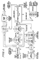
- Figure 1 shows a radio receiver 11 which receives a signal from an antenna 10.
- the radio receiver can be connected to a telephone line.
- the radio receiver can be located in a cellular radio telephone subscriber unit or a cellular radio network base station.
- the radio receiver filters, amplifies and converts the received signal to a suitable frequency and form for digitization in a sampling and digitizing unit 12.
- the numerical samples representative of the complex number-value of the instantaneous radio signal are buffered in a sample buffer memory 13. As a result, the samples can be selectively retrieved under the control of a control unit 16.
- a collection of state memories 15 includes, for each state, a path metric memory element, a B-matrix memory element, a U-vector memory element and a path history memory.
- the path history memory for each state contains a symbol string of previously hypothesized symbols that will become the output of the device if the associated path metric is at some point judged to be the largest.
- the control unit 16 can select the contents of each state memory in turn to be applied to the metric computer 14 along with a selected signal sample retrieved from the buffer memory 13.
- the control unit 16 also informs the metric computer of the state number selected, which corresponds to each as-yet unresolved hypothesis of sequential symbol combinations not yet archived into the state's path history memory. For example, if only one outstanding unresolved symbol hypothesis is permitted in the device (i.e., the device is configured to deal with one symbol-period delayed echoes only), and the symbol is a binary bit, there will be only two state memories and the control unit will just inform the metric computer whether the "1" state or "0" state is currently selected.
- the control unit 16 will inform the metric computer 14 whether symbol 0,1,2 or 3 is selected. If two outstanding unresolved quaternary symbols are permitted, corresponding to the device being configured to deal with up to 2 symbol-period delayed echoes, then the control unit 16 informs the metric computer 14 which of the 16 states 00,01,02,03,10,11,12,13,20,21,22,23,30,31,32 or 33 is currently selected. The metric computer 14 actually requires the complex values that the transmitter transmitted for these symbols. It is immaterial whether the control unit 16 supplies the complex values directly to the metric computer, or whether the metric computer converts symbols into complex values using a model of the transmit modulation process.
- the transmit modulation process is QPSK, in which symbols are represented by a complex vector of constant length and phase angle 45°, 135°, -45° or -135°
- the complex values corresponding to quaternary symbols 0,1,2 and 3 are ( 1 + j ) / 2 , ( - 1 + j ) / 2 , ( 1 - j ) / 2 and ( - 1 - j ) / 2 , respectively.
- the matrix and vector arithmetic unit 14 computes a new metric for a given new symbol hypothesis and each of the previous states selected in turn.
- the largest of the new values is selected to be the new metric value of the state the new symbol hypothesis will be associated with as a new unresolved symbol. Selecting the largest of the new metric values resolves the oldest of the previously unresolved symbol hypotheses and this resolved symbol is then shifted into the associated path history memory.
- one new unresolved symbol is created at each iteration of the device while one old hypothesis is resolved, so that the number of unresolved symbols remains constant and the number of states remains constant.
- the matrix and vector arithmetic unit 14 calculates a new B-matrix and U-vector for each new state.
- the new B and U elements are calculated using the elements of corresponding entities from that old state which gave rise to the largest metric that was selected for the new state.
- a concatenator 20 forms a vector Zn out of the complex values associated with currently unresolved symbols (Sn,S(n-1) ... ) of the control-unit-selected state, plus a new unresolved symbol S(n+1).
- the vector Zn is simply (S(n+1),Sn,S(n-1) .... )
- the complex conjugate of Zn is multiplied by the control-unit-selected B-matrix in a multiplier 21 to generate a new vector Vn.
- the vector Vn is then multiplied by the Zn vector again in the multiplier 22 to yield the scalar signal "b" used in a metric computer 24.
- the vector Vn is also multiplied by a control-unit-selected U-vector in a multiplier 23 to yield a second scalar quantity "a”, also applied to the metric computer 24.
- the other values used in the metric computer are also scalars, namely the current, control-unit-retrieved signal sample r(n+ 1) from buffer memory 13 and the control-unit-selected path metric value M.
- the metric computer 24 combines these values to produce a new metric with the control unit selecting the M,B, and U entities from each state of the state memory.
- the results are temporally stored in a temporary storage 25 so that they can be compared in a comparator 26 to find the largest value.
- the state that gives rise to the largest value and the largest value are determined by the comparator 26. This is called a best predecessor state.
- This resolves the oldest of the unresolved symbol hypotheses to be associated with the state with which the new symbol hypothesis S(n+1) will be associated. This is called the successor state.
- the resolved symbol is appended to the other symbols in the path history of the best predecessor to become the path history of the successor.
- the B and U entities of the best predecessor are updated to become the B and U entities of the successor state.
- the updating is carried out by blocks (27-31) of Figure 2 .
- the block 27 performs outer multiplication of the vector Vn with its own conjugate transpose to form a square matrix. This is scaled by 1/(1+b) in a scaler 28 using the b-value computed by the multiplier 22, then subtracted from the predecessor state's B matrix to obtain the successor state's B-matrix.
- the successor state's U-vector is computed by a multiplier 30 and an adder 31.
- the Zn vector from the concatenator 20 is multiplied by the complex conjugate of the selected received signal sample r(n+ 1) in the multiplier 30.
- the result is then added to the predecessor state's U-vector to form the successor state's U-vector in the adder 31.
- the set of new state memory contents (successor states) become the state memory contents for beginning a new processing cycle to decode signal sample r(n+2).
- the present invention tolerates channel variations and resolves decoded symbols based more on recently processed signal samples than on long past processed signal samples. It may also be realized that "most recently processed” is not necessarily the same as "most recently received", since the use of a buffer memory allows received samples to be processed in time reversed order, or even half in time reversed order and half in non-time-reversed order from a central starting point.
- the arithmetic units illustrated in the blocks of Figures 1-3 should preferably be simplified to the maximum extent by noting whether values are purely real instead of complex and not generating an imaginary part if the values are real. Also, the symbol values for binary modulation are just real and + or -1, allowing great simplification of multipliers 21, 22 and 30. Even when the quaternary symbols of QPSK as mentioned above are used, the common factor of 1/ ⁇ 2 between the real and imaginary parts can be removed leaving only values of +1 and -1, that again allows large simplifications of multipliers 21, 22 and 30.
- the construction of the present invention is however applicable for decoding any representation of digital data by modulating amplitude or phase values of a radio signal or both. It may also be appreciated that the present invention can be applied to the decoding of digital data signals that have been received over a telephone line.
Landscapes
- Engineering & Computer Science (AREA)
- Power Engineering (AREA)
- Computer Networks & Wireless Communication (AREA)
- Signal Processing (AREA)
- Error Detection And Correction (AREA)
- Filters That Use Time-Delay Elements (AREA)
- Cable Transmission Systems, Equalization Of Radio And Reduction Of Echo (AREA)
- Digital Transmission Methods That Use Modulated Carrier Waves (AREA)
- Circuits Of Receivers In General (AREA)
- Dc Digital Transmission (AREA)
Claims (17)
- Dispositif pour démoduler un signal modulé avec des symboles d'informations numériques de façon à extraire lesdits symboles d'informations, comportant :un moyen de réception (11) pour recevoir un signal correspondant à une séquence sn de symboles d'informations transmis sur un canal de communication ;un moyen d'échantillonnage et de numérisation (12) pour produire une séquence de valeurs d'échantillons numériques rn représentatives dudit signal reçu ;caractérisé par
un moyen de mémoire (13) présentant un nombre de mémoires d'état (15) étant chacune associées à une séquence de symboles conjecturée Sn et comportant chacune :une mémoire de métrique de chemin Mn, dans laquelleoù a = Un'Vn est une grandeur scalaire complexe et b = ZnVn est une grandeur scalaire réelle et où Zn est formée en utilisant un symbole conjecturé le plus récent s (n + 1) et des symboles non encore résolus [Sn, S (n - 1), ...] desdits symboles d'information transmis et Vn = BnZn et où Un', Zn' sont des matrices transposées conjuguées de Un, Zn respectivement, et r (n + 1) est le dernier échantillon d'information reçu ;
une mémoire de matrice B, Bn, où Bn = (Sn'Sn)-1 est une matrice carrée dont les éléments dépendent uniquement de la séquence de symboles conjecturés Sn, et où le terme Bn se rapporte aux valeurs matricielles après que n symboles ont été conjecturés où Sn' est une matrice transposée conjuguée de la matrice Sn,
une mémoire de vecteur U, Un, dans laquelle Un est un vecteur présentant une longueur égale au nombre de dispersions temporelles de symboles, L et où Un' = Rn'Sn où Rn' est une matrice transposée conjuguée de la matrice Rn représentant les échantillons numériques rn, et
une mémoire d'historique de chemin ;
un moyen de commande (16) pour récupérer de manière sélective des valeurs à partir dudit moyen de mémoire (13) et commander la synchronisation des opérations connexes ;
un moyen de calcul de métriques (24) pour calculer des métriques candidates M (n + 1) en utilisant une hypothèse du prochain desdits symboles d'informations S (n + 1) à démoduler mise en oeuvre par ledit moyen de commande, et ladite valeur d'échantillon numérique reçue en dernier, des valeurs de métrique de chemin, des matrices B et des vecteurs U et le nombre d'états associés aux métriques candidates sélectionnés par ledit moyen de commande à partir dudit moyen de mémoire ;
un moyen de calcul de meilleur prédécesseur (25 - 26) pour déterminer la meilleure desdites métriques candidates à sélectionner pour une réécriture dans ledit moyen de mémoire avec un vecteur U, un historique de chemin et une matrice B de successeur ; et
des moyens de mise à jour (27 - 31) pour calculer lesdites matrices B, vecteurs U et ledit historique de chemin de successeur en utilisant des valeurs correspondantes associées audit meilleur prédécesseur et à ladite valeur d'échantillon numérique reçue en dernier lieu. - Démodulateur selon la revendication 1, dans lequel ledit moyen de réception (11) est un moyen de réception radio équipé d'une antenne radio.
- Démodulateur selon la revendication 1, dans lequel ledit moyen de réception (11) est connecté à une ligne téléphonique.
- Démodulateur selon la revendication 2, dans lequel ledit moyen de réception (11) est utilisé dans une unité d'abonné de téléphone radio cellulaire.
- Démodulateur selon la revendication 2, dans lequel ledit moyen de réception (11) est utilisé dans une station de base de réseau radio cellulaire.
- Démodulateur selon la revendication 1, dans lequel lesdites matrices B sont modifiées avant l'utilisation dans ledit moyen de calcul de métriques (24) et dans ledit moyen de mise à jour (27 - 31).
- Démodulateur selon la revendication 1, dans lequel lesdits vecteurs U sont modifiés avant l'utilisation dans ledit moyen de calcul de métriques (24) et dans ledit moyen de mise à jour (27 - 31).
- Démodulateur selon la revendication 6, dans lequel lesdites matrices B sont modifiées en extrapolant lesdites matrices B par un facteur prédéterminé.
- Démodulateur selon la revendication 7, dans lequel lesdits vecteurs U sont modifiés en réduisant lesdits vecteurs U par un facteur prédéterminé.
- Démodulateur selon la revendication 6, dans lequel lesdites matrices B sont modifiées en ajoutant une matrice constante auxdites matrices B.
- Démodulateur selon la revendication 10, dans lequel ladite matrice constante ne présente que des éléments diagonaux non nuls.
- Démodulateur selon la revendication 1, dans lequel ledit signal est modulé par des bits d'informations binaires.
- Démodulateur selon la revendication 12, dans lequel ledit procédé de modulation est une modulation par inversion de phase.
- Démodulateur selon la revendication 12, dans lequel ladite modulation change la phase dudit signal.
- Démodulateur selon la revendication 1, dans lequel ledit signal est modulé avec des symboles quaternaires.
- Démodulateur selon la revendication 15, dans lequel ledit procédé de modulation est une modulation par déplacement de phase en quadrature.
- Démodulateur selon la revendication 12, dans lequel ledit procédé de modulation est une modulation quadri-phase décalée.
Applications Claiming Priority (3)
| Application Number | Priority Date | Filing Date | Title |
|---|---|---|---|
| US305727 | 1994-09-14 | ||
| US08/305,727 US5557645A (en) | 1994-09-14 | 1994-09-14 | Channel-independent equalizer device |
| PCT/US1995/011708 WO1996008903A1 (fr) | 1994-09-14 | 1995-09-12 | Demodulateur-compensateur aveugle |
Publications (2)
| Publication Number | Publication Date |
|---|---|
| EP0781481A1 EP0781481A1 (fr) | 1997-07-02 |
| EP0781481B1 true EP0781481B1 (fr) | 2009-01-07 |
Family
ID=23182074
Family Applications (1)
| Application Number | Title | Priority Date | Filing Date |
|---|---|---|---|
| EP95933114A Expired - Lifetime EP0781481B1 (fr) | 1994-09-14 | 1995-09-12 | Demodulateur-compensateur aveugle |
Country Status (8)
| Country | Link |
|---|---|
| US (2) | US5557645A (fr) |
| EP (1) | EP0781481B1 (fr) |
| JP (1) | JPH10505978A (fr) |
| AU (1) | AU688974B2 (fr) |
| DE (1) | DE69535903D1 (fr) |
| FI (1) | FI971054A7 (fr) |
| MX (1) | MX9701907A (fr) |
| WO (1) | WO1996008903A1 (fr) |
Families Citing this family (32)
| Publication number | Priority date | Publication date | Assignee | Title |
|---|---|---|---|---|
| US5943324A (en) * | 1994-01-11 | 1999-08-24 | Ericsson, Inc. | Methods and apparatus for mobile station to mobile station communications in a mobile satellite communication system |
| US5805638A (en) * | 1995-12-04 | 1998-09-08 | Lucent Technologies Inc. | Systems and methods of digital wireless communication using equalization |
| US5802112A (en) * | 1996-01-16 | 1998-09-01 | Transcendat Inc. | Multi-level, multi-frequency interference pattern analog waveform encoding of digital data for transmission |
| US5793807A (en) * | 1996-05-07 | 1998-08-11 | Lucent Technologies Inc. | Multimodulus blind eqalization using piecewise linear contours |
| US6185259B1 (en) | 1996-06-12 | 2001-02-06 | Ericsson Inc. | Transmitter/receiver for GMSK and offset-QAM |
| US6320914B1 (en) * | 1996-12-18 | 2001-11-20 | Ericsson Inc. | Spectrally efficient modulation using overlapped GMSK |
| US6215762B1 (en) | 1997-07-22 | 2001-04-10 | Ericsson Inc. | Communication system and method with orthogonal block encoding |
| US6185258B1 (en) | 1997-09-16 | 2001-02-06 | At&T Wireless Services Inc. | Transmitter diversity technique for wireless communications |
| US5887035A (en) * | 1997-10-31 | 1999-03-23 | Ericsson, Inc. | Method for joint equalization and detection of multiple user signals |
| WO1999023766A2 (fr) | 1997-10-31 | 1999-05-14 | At & T Wireless Services, Inc. | Detection par probabilite maximale a faible complexite de codes d'espace concatenes pour applications sans fil |
| US6049574A (en) * | 1998-04-17 | 2000-04-11 | Trustees Of Tufts College | Blind adaptive equalization using cost function that measures dissimilarity between the probability distributions of source and equalized signals |
| AT407933B (de) * | 1998-06-09 | 2001-07-25 | Juha Dipl Ing Laurila | Verfahren zur trennung und zur detektion von gleichkanal-signalen |
| US6038262A (en) * | 1998-06-09 | 2000-03-14 | Transcendata, Inc. | Method and apparatus for compensation of electro-magnetic distortion using weighted feedback delay for amplitude coded sinusoidal waveform generation and transmission |
| US6567475B1 (en) | 1998-12-29 | 2003-05-20 | Ericsson Inc. | Method and system for the transmission, reception and processing of 4-level and 8-level signaling symbols |
| US6507602B1 (en) | 1999-01-07 | 2003-01-14 | Ericsson, Inc. | Smoothing receiver channel estimates using spectral estimation |
| US6347125B1 (en) | 1999-01-11 | 2002-02-12 | Ericsson Inc. | Reduced complexity demodulator for multi-bit symbols |
| US6556634B1 (en) | 1999-02-10 | 2003-04-29 | Ericsson, Inc. | Maximum likelihood rake receiver for use in a code division, multiple access wireless communication system |
| US6304216B1 (en) * | 1999-03-30 | 2001-10-16 | Conexant Systems, Inc. | Signal detector employing correlation analysis of non-uniform and disjoint sample segments |
| US6463099B1 (en) * | 1999-05-18 | 2002-10-08 | The Hong Kong University Of Science And Technology | Blind channel equalizers and methods of blind channel equalization |
| KR100636512B1 (ko) * | 1999-08-31 | 2006-10-18 | 엘지전자 주식회사 | 비터비 복호기의 가지 메트릭 장치 |
| US6570910B1 (en) * | 1999-10-25 | 2003-05-27 | Ericsson Inc. | Baseband processor with look-ahead parameter estimation capabilities |
| US6484285B1 (en) | 2000-02-07 | 2002-11-19 | Ericsson, Inc. | Tailbiting decoder and method |
| US6625236B1 (en) | 2000-02-08 | 2003-09-23 | Ericsson Inc. | Methods and systems for decoding symbols by combining matched-filtered samples with hard symbol decisions |
| US7079586B1 (en) * | 2000-03-16 | 2006-07-18 | Koninklijke Philips Electronics N.V. | Systems and methods for optimal distribution of symbols in a fixed size data packet to improve receiver performance |
| US7443826B1 (en) | 2000-10-04 | 2008-10-28 | Telefonaktiebolaget L M Ericsson (Publ) | Method and apparatus for automatic frequency control in a CDMA receiver |
| US7440489B2 (en) * | 2001-08-07 | 2008-10-21 | Ericsson Inc. | Method and apparatus for selective demodulation and decoding of communications signals |
| EP1442570B1 (fr) * | 2001-11-09 | 2005-05-04 | Infineon Technologies AG | Egalisation par l'algorithme de viterbi au moyen d'un ensemble de tables pour maintenir a disposition des valeurs de signaux reconstruites servant au calcul de metriques de transition |
| WO2003077488A1 (fr) * | 2002-03-04 | 2003-09-18 | Glowlink Communications Technology, Inc. | Detection et mesure des interferences contenues dans une porteuse numerique |
| US7212566B2 (en) * | 2002-06-26 | 2007-05-01 | Nokia Corporation | Apparatus, and associated method, for performing joint equalization in a multiple-input, multiple-output communication system |
| GB2395871B (en) * | 2002-11-28 | 2006-01-11 | Toshiba Res Europ Ltd | Signal estimation methods and apparatus |
| JP4812454B2 (ja) * | 2006-02-13 | 2011-11-09 | ソニー株式会社 | 復調装置および方法、並びにプログラム |
| US20090086806A1 (en) * | 2007-09-27 | 2009-04-02 | Nanoamp Solutions Inc. (Cayman) | Time varying equalization |
Family Cites Families (9)
| Publication number | Priority date | Publication date | Assignee | Title |
|---|---|---|---|---|
| DE3911999A1 (de) * | 1989-04-12 | 1990-10-18 | Philips Patentverwaltung | Uebertragungssystem |
| JP2960436B2 (ja) * | 1989-06-26 | 1999-10-06 | 株式会社日立製作所 | 非線形データ伝送システム用受信器 |
| SE464902B (sv) * | 1989-10-24 | 1991-06-24 | Ericsson Telefon Ab L M | Foerfarande att adaptera en viterbialgoritm till en kanal med skiftande oeverfoeringsegenskaper samt en anordning foer genomfoerande av foerfarandet |
| DE4001592A1 (de) * | 1989-10-25 | 1991-05-02 | Philips Patentverwaltung | Empfaenger fuer digitales uebertragungssystem |
| US5263033A (en) * | 1990-06-22 | 1993-11-16 | At&T Bell Laboratories | Joint data and channel estimation using fast blind trellis search |
| DE4038251A1 (de) * | 1990-11-30 | 1992-06-04 | Philips Patentverwaltung | Entzerrer fuer ein digitales uebertragungssystem |
| US5331666A (en) * | 1992-06-08 | 1994-07-19 | Ericsson Ge Mobile Communications Inc. | Adaptive maximum likelihood demodulator |
| US5335250A (en) * | 1992-10-22 | 1994-08-02 | Ericsson Ge Mobile Communications Inc. | Method and apparatus for bidirectional demodulation of digitally modulated signals |
| US5347541A (en) * | 1992-11-02 | 1994-09-13 | The Regents Of The Univ. Of California | Apparatus and method for utilizing a blind equalizer based on a Bayesian symbol sequence estimator for use in digital communication |
-
1994
- 1994-09-14 US US08/305,727 patent/US5557645A/en not_active Expired - Lifetime
-
1995
- 1995-09-12 DE DE69535903T patent/DE69535903D1/de not_active Expired - Fee Related
- 1995-09-12 AU AU35893/95A patent/AU688974B2/en not_active Ceased
- 1995-09-12 JP JP8510354A patent/JPH10505978A/ja not_active Withdrawn
- 1995-09-12 WO PCT/US1995/011708 patent/WO1996008903A1/fr not_active Ceased
- 1995-09-12 MX MX9701907A patent/MX9701907A/es unknown
- 1995-09-12 EP EP95933114A patent/EP0781481B1/fr not_active Expired - Lifetime
-
1996
- 1996-06-03 US US08/657,345 patent/US5619533A/en not_active Expired - Lifetime
-
1997
- 1997-03-13 FI FI971054A patent/FI971054A7/fi unknown
Also Published As
| Publication number | Publication date |
|---|---|
| AU688974B2 (en) | 1998-03-19 |
| WO1996008903A1 (fr) | 1996-03-21 |
| FI971054A0 (fi) | 1997-03-13 |
| EP0781481A1 (fr) | 1997-07-02 |
| US5619533A (en) | 1997-04-08 |
| AU3589395A (en) | 1996-03-29 |
| JPH10505978A (ja) | 1998-06-09 |
| DE69535903D1 (de) | 2009-02-26 |
| MX9701907A (es) | 1997-06-28 |
| US5557645A (en) | 1996-09-17 |
| FI971054A7 (fi) | 1997-05-14 |
Similar Documents
| Publication | Publication Date | Title |
|---|---|---|
| EP0781481B1 (fr) | Demodulateur-compensateur aveugle | |
| MXPA97001907A (en) | Blind equalizing apparatus | |
| US4468786A (en) | Nonlinear equalizer for correcting intersymbol interference in a digital data transmission system | |
| JP4421682B2 (ja) | ディジタル伝送システムにおける受信機のための拡張されたチャンネル推定等化器 | |
| Hsu | Square root Kalman filtering for high-speed data received over fading dispersive HF channels | |
| Mueller | Least‐squares algorithms for adaptive equalizers | |
| JP2677750B2 (ja) | 受信システム | |
| US5231648A (en) | Adaptive equalizer for digital cellular radio | |
| GB2247812A (en) | Equalizer for linear modulated signal on radio channel | |
| EP1430672B1 (fr) | Calcul rapide de coefficients d egaliseur a decision retroac tive | |
| US6775322B1 (en) | Equalizer with adaptive pre-filter | |
| US5111484A (en) | Adaptive distortion canceller | |
| ITTO970633A1 (it) | Procedimento e sistema per la ricezione di segnali digitali | |
| Smalley | Equalization concepts: a tutorial | |
| JP3099745B2 (ja) | 自動等化器 | |
| JPH0511449B2 (fr) | ||
| US5914987A (en) | Method of recovering symbols of a digitally modulated radio signal | |
| JPH04223708A (ja) | 等化器におけるfirフィルタ係数の決定方法 | |
| US6084929A (en) | Method and apparatus for channel tracking | |
| US20030118094A1 (en) | Mixed time and frequency domains equalization algorithm for ADSL systems | |
| JP2003529241A (ja) | チャネル等化するための方法 | |
| GB2225883A (en) | Method of determining the tap weights of a decision feedback equaliser | |
| CN1163033A (zh) | 盲均衡装置 | |
| CA2199709C (fr) | Dispositif egalisateur a canaux independant | |
| US20090185611A1 (en) | Method for calculating filter coefficients for an equaliser in a communication receiver using hermitian optimisation |
Legal Events
| Date | Code | Title | Description |
|---|---|---|---|
| PUAI | Public reference made under article 153(3) epc to a published international application that has entered the european phase |
Free format text: ORIGINAL CODE: 0009012 |
|
| 17P | Request for examination filed |
Effective date: 19970221 |
|
| AK | Designated contracting states |
Kind code of ref document: A1 Designated state(s): DE FR GB SE |
|
| RIN1 | Information on inventor provided before grant (corrected) |
Inventor name: DENT, PAUL, W. |
|
| RAP1 | Party data changed (applicant data changed or rights of an application transferred) |
Owner name: ERICSSON INC. |
|
| 17Q | First examination report despatched |
Effective date: 20070824 |
|
| GRAP | Despatch of communication of intention to grant a patent |
Free format text: ORIGINAL CODE: EPIDOSNIGR1 |
|
| GRAS | Grant fee paid |
Free format text: ORIGINAL CODE: EPIDOSNIGR3 |
|
| GRAA | (expected) grant |
Free format text: ORIGINAL CODE: 0009210 |
|
| AK | Designated contracting states |
Kind code of ref document: B1 Designated state(s): DE FR GB SE |
|
| REG | Reference to a national code |
Ref country code: GB Ref legal event code: FG4D |
|
| REF | Corresponds to: |
Ref document number: 69535903 Country of ref document: DE Date of ref document: 20090226 Kind code of ref document: P |
|
| PG25 | Lapsed in a contracting state [announced via postgrant information from national office to epo] |
Ref country code: SE Free format text: LAPSE BECAUSE OF FAILURE TO SUBMIT A TRANSLATION OF THE DESCRIPTION OR TO PAY THE FEE WITHIN THE PRESCRIBED TIME-LIMIT Effective date: 20090407 |
|
| PLBE | No opposition filed within time limit |
Free format text: ORIGINAL CODE: 0009261 |
|
| STAA | Information on the status of an ep patent application or granted ep patent |
Free format text: STATUS: NO OPPOSITION FILED WITHIN TIME LIMIT |
|
| 26N | No opposition filed |
Effective date: 20091008 |
|
| REG | Reference to a national code |
Ref country code: FR Ref legal event code: ST Effective date: 20100531 |
|
| PG25 | Lapsed in a contracting state [announced via postgrant information from national office to epo] |
Ref country code: FR Free format text: LAPSE BECAUSE OF NON-PAYMENT OF DUE FEES Effective date: 20090930 Ref country code: DE Free format text: LAPSE BECAUSE OF NON-PAYMENT OF DUE FEES Effective date: 20100401 |
|
| REG | Reference to a national code |
Ref country code: GB Ref legal event code: 732E Free format text: REGISTERED BETWEEN 20130808 AND 20130814 |
|
| PGFP | Annual fee paid to national office [announced via postgrant information from national office to epo] |
Ref country code: GB Payment date: 20130919 Year of fee payment: 19 |
|
| REG | Reference to a national code |
Ref country code: GB Ref legal event code: 732E Free format text: REGISTERED BETWEEN 20131205 AND 20131211 |
|
| REG | Reference to a national code |
Ref country code: GB Ref legal event code: 732E Free format text: REGISTERED BETWEEN 20140605 AND 20140611 |
|
| GBPC | Gb: european patent ceased through non-payment of renewal fee |
Effective date: 20140912 |
|
| PG25 | Lapsed in a contracting state [announced via postgrant information from national office to epo] |
Ref country code: GB Free format text: LAPSE BECAUSE OF NON-PAYMENT OF DUE FEES Effective date: 20140912 |