EP0781570A2 - Dispositif pour vider et remplir un évaporateur d'anesthésique - Google Patents
Dispositif pour vider et remplir un évaporateur d'anesthésique Download PDFInfo
- Publication number
- EP0781570A2 EP0781570A2 EP96660104A EP96660104A EP0781570A2 EP 0781570 A2 EP0781570 A2 EP 0781570A2 EP 96660104 A EP96660104 A EP 96660104A EP 96660104 A EP96660104 A EP 96660104A EP 0781570 A2 EP0781570 A2 EP 0781570A2
- Authority
- EP
- European Patent Office
- Prior art keywords
- anaesthetic
- filling
- container
- liquid container
- discharge conduit
- Prior art date
- Legal status (The legal status is an assumption and is not a legal conclusion. Google has not performed a legal analysis and makes no representation as to the accuracy of the status listed.)
- Granted
Links
Images
Classifications
-
- A—HUMAN NECESSITIES
- A61—MEDICAL OR VETERINARY SCIENCE; HYGIENE
- A61M—DEVICES FOR INTRODUCING MEDIA INTO, OR ONTO, THE BODY; DEVICES FOR TRANSDUCING BODY MEDIA OR FOR TAKING MEDIA FROM THE BODY; DEVICES FOR PRODUCING OR ENDING SLEEP OR STUPOR
- A61M16/00—Devices for influencing the respiratory system of patients by gas treatment, e.g. ventilators; Tracheal tubes
- A61M16/10—Preparation of respiratory gases or vapours
- A61M16/14—Preparation of respiratory gases or vapours by mixing different fluids, one of them being in a liquid phase
- A61M16/18—Vaporising devices for anaesthetic preparations
- A61M16/183—Filling systems
Definitions
- the invention relates to an arrangement in connection with an anaesthetic vaporizer, said arrangement comprising a filling head to be connected to a liquid container of the anaesthetic vaporizer, said filling head being provided with a connection point for an anaesthetic supply container or the like and a filling conduit adapted to form a flow connection between the connection point for an anaesthetic supply container or the like and the liquid container of the anaesthetic vaporizer for filling the liquid container with an anaesthetic, and a discharge conduit adapted to form a passage through which the anaesthetic in the liquid container of the anaesthetic vaporizer can be discharged to an anaesthetic supply container or the like.
- All anaesthetic vaporizers of the prior art comprise a liquid container from which an anaesthetic is conducted to the other elements of the vaporizer either as vapour or liquid.
- the liquid in the container is consumed during anaesthesia, wherefore anaesthetic must naturally be added to the container from time to time. Sometimes it is also necessary to empty the liquid container of the anaesthetic.
- standards e.g. CSA Z168.3, item 12.2.2.1, define that it must be possible to empty the vaporizer of the anaesthetic.
- the anaesthetic liquid container is both filled and emptied through a separate key-filler adaptor provided between the anaesthetic bottle and the container.
- the anaesthetic bottle In the filling position, the anaesthetic bottle is located above the filling mechanism and the liquid surface of the anaesthetic container, whereby the anaesthetic liquid flows from the bottle to the container under the force of gravity.
- the emptying position the anaesthetic bottle is located below the filling mechanism and the liquid surface of the liquid container, whereby the anaesthetic liquid flows from the container to the bottle under the force of gravity.
- the filling head of the anaesthetic liquid container may comprise separate conduits for filling and emptying. In this case, there is a separate discharge valve for emptying. In some solutions, such as the AladinTM liquid container of Datex-Engström, the same conduit is used for both filling and emptying, wherefore a separate discharge valve is not needed.
- U.S. Patent No. 5,505,236 discloses a filling mechanism according to which a container is filled through a filling head fixedly mounted on an anaesthetic bottle. During the filling, the filling head engages directly with a complementary portion provided in the filling head of the anaesthetic liquid container.
- a filling mechanism has been found to be technically better and easier to use than the key-filler-type filling mechanism described above.
- the container cannot be emptied through the same complementary portion and filling head. In this solution, the container is emptied through a separate emptying port, which must be opened with a tool.
- the filling head of the anaesthetic bottle is provided with a separate emptying adaptor, which can be connected to the emptying port provided in the container.
- a separate loose emptying adaptor is required.
- the solution disclosed in U.S. Patent No. 5,381,836 does not allow the container to be filled and emptied through the same complementary portion, either.
- the discharge conduit is adapted to form a flow connection between the liquid container and the connection point provided in the filling head for an anaesthetic supply container or the like, and that the discharge conduit is provided with a separate cut-off device arranged to close the flow connection formed by the discharge conduit.
- the most significant advantage of the invention is that the anaesthetic vaporizer is filled and emptied through one and the same connection point provided for the filling container or the like, i.e. through the same complementary part. No separate parts or adaptors are needed, wherefore the container can be both filled and emptied in a simple manner.
- the invention also eliminates the possibility of the anaesthetic agent draining out in an uncontrolled manner as a result of misuse of the emptying mechanism.
- the invention makes it possible to provide a solution which does not allow the container to be filled bypassing the filling conduit and overfill mechanism.
- Yet another advantage of the invention is that it is suitable for very different solutions, particularly a vaporizer or liquid container which can be turned without breaking the device or risking the patient's health.
- the arrangement of the invention is simple in construction, wherefore the start-up and operating costs will be low.
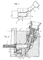
- Figure 1 is a schematic view of the operation and structure of the arrangement of the invention.
- Reference numeral 1 indicates a liquid container of an anaesthetic vaporizer.
- Reference numeral 2 designates a filling head to be connected to the anaesthetic vaporizer.
- the filling head is provided with a connection point 3 for an anaesthetic supply container or the like 4.
- Reference numeral 5 indicates a filling conduit which forms a flow connection between the connection point 3 for the anaesthetic supply container or the like 4 and the liquid container 1 of the anaesthetic vaporizer.
- Reference numeral 6 designates a discharge conduit, through which the anaesthetic in the liquid container 1 of the anaesthetic vaporizer can be discharged to the anaesthetic supply container or the like.
- anaesthetic supply container or the like' refers in this example to an anaesthetic bottle, i.e. a container serving as an anaesthetic transport or supply container, or some other container adapted to engage with the connection point 3.
- Reference numeral 7 denotes a mechanism for preventing overfill.
- the discharge conduit 6 forms a flow connection between the liquid container 1 and the connection point 3 provided in the filling head for the anaesthetic supply container of the like 4.
- the discharge conduit 6 is provided with a separate cut-off device 8, which closes the flow connection formed by the discharge conduit 6.
- the separate cut-off device 8 is indicated in Figure 1 by a broken line.
- the separate cut-off device 8 can be formed in different ways, as will be explained below.
- Figure 2 illustrates a first, or the most preferred, embodiment of the arrangement of the invention.
- the same numbers have the same significance as in Figure 1.
- the anaesthetic supply container or the like 4 is provided with a valve mechanism 9 which engages with the complementary part 10 in the filling head.
- the anaesthetic flows through the filling conduit 5 and the overfill prevention mechanism 7 to the liquid container 1 of the anaesthetic vaporizer, as indicated by arrows in Figure 2.
- the filling head is provided with a discharge conduit 6, which forms a flow connection between the liquid container 1 and the connection point 3, as stated above.
- the discharge conduit 6 is provided with a separate cut-off device 8 for closing the discharge conduit 6 when it is not in use.
- the cut-off device 8 comprises a mechanical element, which may be a cut-off valve 11 (e.g. a screw valve) or a cut-off member 12 (e.g. a ball).
- the cut-off member 12 is arranged to move against the sealing surface 13 to close the discharge conduit 6 whenever the filling head 2 is not in the liquid container emptying position (i.e.
- the cut-off device may also be a combination of a cut-off valve 11 and a cut-off member, as in the example of Figure 2.
- the cut-off member 12 can be arranged to move to a position closing the discharge conduit under the force of gravity, for example, such that the discharge conduit is open only when the filling head 2 is in the emptying position.
- the filling head 2 can be fixedly mounted on the container 1, whereby the filling head is placed in the emptying position by turning the container 1 to this position.
- the filling head 2 can be mounted displaceably on the container 1: the filling head 2 can thus be displaced (e.g. turned from the filling position to the emptying position or vice versa) in such a manner that the actual container remains stationary.
- the valve 11 is a screw valve to be moved with a suitable tool, e.g. a hexagon spanner.
- the cut-off valve may also be a valve other than the screw valve shown in Figure 2.
- An example of other suitable valves is a disc valve.
- the cut-off valve When the cut-off valve is a disc valve, it can naturally be mounted according to the invention such that the pressure of the liquid container closes the valve (pressure to close), or such that the pressure of the liquid container opens the valve (pressure to open).
- the cut-off valve may also be a ball valve, seat valve or some other valve with the same function.
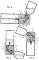
- Figures 3 to 5 show the arrangement of the invention during filling, i.e. in the same situation as in Figure 2.
- Figure 4 illustrates the emptying process, i.e. a situation where the container is emptied through a discharge conduit to an anaesthetic supply container or the like.
- Figure 5 illustrates a situation where someone is trying to fill the container erroneously through the discharge conduit.
- Figure 3 illustrates the operation of the arrangement of the invention during filling.
- the liquid container 1 can be filled, for example, using the valve mechanism principle disclosed in the above-mentioned U.S. Patent No. 5,505,236. It would also be possible to use the principle disclosed in U.S. Patent No. 5,381,836.
- the anaesthetic flows from the supply container of the like to the connection point 3.
- the connection point 3 is formed by means of various sealings, valves and other structures known per se. From the connection point 3, the anaesthetic flows through the filling conduit 5 and the overflow prevention mechanism 7 to the container 1.
- the overflow prevention mechanism 7 is an intermediate container formed from a curved tubular portion, e.g.
- the separate cut-off device 8 of the discharge conduit 6 is in a position closing the discharge conduit.
- the separate cut-off device 8 consists of a disc valve 11 and a ball 12 moving under the force of gravity.
- Figure 4 illustrates the operation of the arrangement of the invention during emptying.
- the discharge conduit which is separate from the filling conduit, is connected to the filling conduit.
- the connection is effected in the example of Figure 4 by turning the container 1 - and thereby also the filling head 2 - to the emptying position and opening the cut-off valve 11.
- the ball 12 moves by gravity from the sealing surface to a position in which the discharge conduit 6 is open, whereby the anaesthetic is allowed to flow to the filling conduit and further to the supply container or the like 4, as indicated by the arrows in Figure 4.
- the embodiment shown in Figure 4 comprises both a cut-off valve 11 operated by a user and a cut-off member, or ball 12, operating by gravity.
- Figure 5 illustrates the arrangement of the invention during misuse, i.e. in a situation where someone is trying to fill the container 1 through the discharge conduit 6.
- the cut-off valve 11 can be opened in the position of Figure 5, but the ball 12 closes the discharge conduit 6 under the force of gravity, whereby it is impossible to fill the container through the conduit.
- the container can be emptied only when the filling head moves to the emptying position, whereby the cut-off member (e.g. a ball) closing the discharge conduit rolls away from the sealing surface and thereby opens the discharge conduit.
- the liquid surface of the liquid container 1 is above the liquid surface of the anaesthetic supply container or the like, wherefore overfill is prevented.
Landscapes
- Health & Medical Sciences (AREA)
- Anesthesiology (AREA)
- Emergency Medicine (AREA)
- Pulmonology (AREA)
- Engineering & Computer Science (AREA)
- Biomedical Technology (AREA)
- Heart & Thoracic Surgery (AREA)
- Hematology (AREA)
- Life Sciences & Earth Sciences (AREA)
- Animal Behavior & Ethology (AREA)
- General Health & Medical Sciences (AREA)
- Public Health (AREA)
- Veterinary Medicine (AREA)
- Filling Or Discharging Of Gas Storage Vessels (AREA)
- Feeding And Controlling Fuel (AREA)
Applications Claiming Priority (6)
| Application Number | Priority Date | Filing Date | Title |
|---|---|---|---|
| FI956354A FI956354A0 (fi) | 1995-12-29 | 1995-12-29 | Anordning foer begraensning av paofyllning av en behaollare foer anestetiska vaetskor |
| FI956354 | 1995-12-29 | ||
| FI961698 | 1996-04-18 | ||
| FI961698A FI102145B (fi) | 1995-12-29 | 1996-04-18 | Sovitelma anestesianestesäiliön täytön rajoittamiseksi |
| FI964205A FI104791B (fi) | 1995-12-29 | 1996-10-18 | Sovitelma anestesiahöyrystimen yhteydessä |
| FI964205 | 1996-10-18 |
Publications (3)
| Publication Number | Publication Date |
|---|---|
| EP0781570A2 true EP0781570A2 (fr) | 1997-07-02 |
| EP0781570A3 EP0781570A3 (fr) | 1998-01-07 |
| EP0781570B1 EP0781570B1 (fr) | 2002-03-20 |
Family
ID=27241657
Family Applications (1)
| Application Number | Title | Priority Date | Filing Date |
|---|---|---|---|
| EP96660104A Expired - Lifetime EP0781570B1 (fr) | 1995-12-29 | 1996-12-20 | Dispositif pour vider et remplir un évaporateur d'anesthésique |
Country Status (5)
| Country | Link |
|---|---|
| US (1) | US5758640A (fr) |
| EP (1) | EP0781570B1 (fr) |
| JP (1) | JPH09290022A (fr) |
| DE (1) | DE69619951T2 (fr) |
| FI (1) | FI104791B (fr) |
Cited By (3)
| Publication number | Priority date | Publication date | Assignee | Title |
|---|---|---|---|---|
| EP0909567A3 (fr) * | 1997-09-24 | 1999-12-08 | Instrumentarium Oy | Arrangement pour l'éjection contrÔlée dans un dispositif d'anesthésie |
| FR2843030A1 (fr) * | 2002-07-31 | 2004-02-06 | Draeger Medical Ag | Systeme humidificateur de gaz respiratoire |
| EP1344546A3 (fr) * | 2002-03-15 | 2004-05-26 | Datex-Ohmeda Inc. | Système de remplissage d'un évaporateur d'anesthésique |
Families Citing this family (11)
| Publication number | Priority date | Publication date | Assignee | Title |
|---|---|---|---|---|
| US6279622B1 (en) * | 2000-02-07 | 2001-08-28 | Ethicon, Inc. | Method and system for delivering and metering liquid sterilant |
| FR2817757B1 (fr) * | 2000-12-09 | 2004-09-03 | Draeger Medical Ag | Dispositif d'alimentation en anesthesique d'un appareil medical |
| SE0103473D0 (sv) * | 2001-10-18 | 2001-10-18 | Siemens Elema Ab | Kopplingssystem |
| DE102004063883B3 (de) * | 2004-12-21 | 2006-04-20 | Dräger Medical AG & Co. KG | Füllsystem für einen Narkosemittelverdunster |
| US7784504B2 (en) * | 2006-03-06 | 2010-08-31 | Baxter International Inc. | Adapters for use with an anesthetic vaporizer |
| US8522839B2 (en) * | 2006-03-06 | 2013-09-03 | Baxter International Inc. | Adapters for use with an anesthetic vaporizer |
| US7886780B2 (en) * | 2007-03-30 | 2011-02-15 | General Electric Company | Method and apparatus for preventing drug reservoir overfill |
| US8534328B2 (en) * | 2008-04-09 | 2013-09-17 | Baxter International Inc. | Adapters for use with an anesthetic vaporizer |
| US7882970B2 (en) * | 2008-07-02 | 2011-02-08 | Baxter Healthcare Corporation | Anesthetic container |
| EP2432541B1 (fr) * | 2009-05-20 | 2013-05-01 | Baxter International Inc | Contenant et produit pharmaceutique |
| CN103921962B (zh) * | 2014-04-22 | 2016-01-20 | 成都中牧生物药业有限公司 | 一种药料灌装机构 |
Family Cites Families (18)
| Publication number | Priority date | Publication date | Assignee | Title |
|---|---|---|---|---|
| GB1224478A (en) * | 1967-11-29 | 1971-03-10 | Cyprane Ltd | Improvements in volatile anaesthetic vapourising apparatus |
| GB1193241A (en) * | 1968-01-05 | 1970-05-28 | Cyprane Ltd | Improvements in or relating to Volatile Anaesthetic Vaporising apparatus and a Filling System therefor |
| US3842870A (en) * | 1970-07-20 | 1974-10-22 | Continental Water Cond | Quick-disconnect manifold assembly |
| US4883049A (en) * | 1985-06-13 | 1989-11-28 | Southmedic Incorporated | Apparatus for use in refilling an anesthetic vaporizer |
| DE3523947A1 (de) * | 1985-07-04 | 1987-01-08 | Draegerwerk Ag | Narkosemittelverdunster mit auswechselbarer verdunsterkammer |
| DE3544302C1 (de) * | 1985-12-14 | 1987-05-14 | Draegerwerk Ag | UEberlaufsicherung an einem Narkosemittelbehaelter |
| US4719949A (en) * | 1986-06-30 | 1988-01-19 | Mobil Oil Corporation | Automotive nozzle-actuated refueling emission system shutoff valve |
| US4747508A (en) * | 1987-03-09 | 1988-05-31 | General Motors Corporation | Fuel tank venting |
| DE4022492C1 (fr) * | 1990-07-14 | 1991-06-13 | Draegerwerk Ag, 2400 Luebeck, De | |
| GB9101560D0 (en) * | 1991-01-24 | 1991-03-06 | Boc Group Plc | Fluid delivery system |
| FI93312C (fi) * | 1992-07-10 | 1995-03-27 | Instrumentarium Oy | Kytkentälaitteisto ja menetelmä astian kytkemiseksi kytkentälaitteistoon ja sitä kautta nestesäiliöön |
| GB2279016B (en) * | 1993-06-14 | 1997-04-09 | Blease Medical Equipment Limit | Vaporizer overfill safety device |
| CA2110851C (fr) * | 1993-12-07 | 2003-04-01 | Technimeca Medic (2002) Inc. | Dispositif servant a prevenir les bouchons de gaz pendant le transfert d'un liquide en circuit ferme, amenagement comprenant le dispositif, et methode d'utilisation connexe |
| IT1269700B (it) * | 1994-01-07 | 1997-04-15 | Abbott Lab | Sistema e apparecchiatura per collegare un contenitore di anestetico ad un vaporizzatore |
| FI94097C (fi) * | 1994-01-24 | 1995-07-25 | Instrumentarium Oy | Sovitelma anestesianestesäiliön ylitäytön estämiseksi |
| US5505236A (en) * | 1994-04-04 | 1996-04-09 | Abbott Laboratories | Anesthetic vaporizer filling system |
| FI96384C (fi) * | 1994-10-18 | 1996-06-25 | Instrumentarium Oy | Sovitelma anestesiahöyrystimen täyttöä varten |
| US5478506A (en) * | 1994-11-17 | 1995-12-26 | Southmedic Inc. | Key-fill vaporizer adaptor with overfill protection |
-
1996
- 1996-10-18 FI FI964205A patent/FI104791B/fi active
- 1996-12-20 EP EP96660104A patent/EP0781570B1/fr not_active Expired - Lifetime
- 1996-12-20 DE DE69619951T patent/DE69619951T2/de not_active Expired - Lifetime
- 1996-12-27 JP JP8351518A patent/JPH09290022A/ja active Pending
- 1996-12-27 US US08/774,270 patent/US5758640A/en not_active Expired - Lifetime
Cited By (6)
| Publication number | Priority date | Publication date | Assignee | Title |
|---|---|---|---|---|
| EP0909567A3 (fr) * | 1997-09-24 | 1999-12-08 | Instrumentarium Oy | Arrangement pour l'éjection contrÔlée dans un dispositif d'anesthésie |
| US6394087B1 (en) | 1997-09-24 | 2002-05-28 | Instrumentarium Corp. | Arrangement in anesthesia apparatus |
| EP1344546A3 (fr) * | 2002-03-15 | 2004-05-26 | Datex-Ohmeda Inc. | Système de remplissage d'un évaporateur d'anesthésique |
| US6929041B2 (en) | 2002-03-15 | 2005-08-16 | Datex-Ohmeda, Inc. | Keyed anesthetic vaporizer filling system |
| FR2843030A1 (fr) * | 2002-07-31 | 2004-02-06 | Draeger Medical Ag | Systeme humidificateur de gaz respiratoire |
| AU2003227324B2 (en) * | 2002-07-31 | 2008-02-28 | Draeger Medical Gmbh | Respiratory gas humidifier system for a patient |
Also Published As
| Publication number | Publication date |
|---|---|
| EP0781570A3 (fr) | 1998-01-07 |
| JPH09290022A (ja) | 1997-11-11 |
| EP0781570B1 (fr) | 2002-03-20 |
| FI964205A7 (fi) | 1997-06-30 |
| FI104791B (fi) | 2000-04-14 |
| DE69619951T2 (de) | 2002-08-29 |
| US5758640A (en) | 1998-06-02 |
| DE69619951D1 (de) | 2002-04-25 |
| FI964205A0 (fi) | 1996-10-18 |
Similar Documents
| Publication | Publication Date | Title |
|---|---|---|
| EP0781570B1 (fr) | Dispositif pour vider et remplir un évaporateur d'anesthésique | |
| US6261267B1 (en) | Automatic IV shut off valve | |
| WO2002053087A3 (fr) | Systeme d'administration de produits pharmaceutiques | |
| EP0264115B1 (fr) | Emballage jettable pour sirop avec soupape intégrée | |
| CA2268237A1 (fr) | Bec anti-eclaboussures | |
| BR9915388A (pt) | Torneiras e recipientes para dispensar fluidos | |
| CN101119869A (zh) | 用于加油管的可无盖封闭的接管端 | |
| IE60555B1 (en) | Shut-off valve for juice dispensing system | |
| GB2240612A (en) | Tap for compressed or liquefied gas | |
| GB2252301A (en) | Shutoff valve for storage tank | |
| JP4191279B2 (ja) | 麻酔用蒸発装置 | |
| EP0781571B1 (fr) | Système pour remplir un évaporateur d'anesthésique | |
| CZ20003138A3 (cs) | Dávkovací zařízení pro ukládací zásobník | |
| NZ328667A (en) | Valve apparatus for use in fluid storage vessels has a filling valve and an outlet valve operatively connected | |
| US5996860A (en) | Momentary buoyant gate system | |
| EP0272906A3 (fr) | Robinets pour fûts et bouteilles sous pression | |
| US4715370A (en) | Overflow trap for anesthetics | |
| CA2309426C (fr) | Dispositif distributeur et ensemble recipient le comprenant | |
| EP1853511B1 (fr) | Robinet de distribution pour recipients elastiques | |
| AU688651B2 (en) | Discharge and fill device for a gas cylinder | |
| EP0280291A1 (fr) | Soupapes sphériques munies d'une sortie pour l'élimination des résidus | |
| DE29825138U1 (de) | Getränkezapfaufbau | |
| EP0614851A1 (fr) | Tête d'accouplement rapide pour récipient contenant une boisson sous pression | |
| AU746145B2 (en) | Tap for removing fluid from a container | |
| JPH05507258A (ja) | 粘性流体の多路容器用機械式カップリング |
Legal Events
| Date | Code | Title | Description |
|---|---|---|---|
| PUAI | Public reference made under article 153(3) epc to a published international application that has entered the european phase |
Free format text: ORIGINAL CODE: 0009012 |
|
| 17P | Request for examination filed |
Effective date: 19961227 |
|
| AK | Designated contracting states |
Kind code of ref document: A2 Designated state(s): DE FR GB IT NL SE |
|
| PUAL | Search report despatched |
Free format text: ORIGINAL CODE: 0009013 |
|
| AK | Designated contracting states |
Kind code of ref document: A3 Designated state(s): DE FR GB IT NL SE |
|
| 17Q | First examination report despatched |
Effective date: 20001009 |
|
| GRAG | Despatch of communication of intention to grant |
Free format text: ORIGINAL CODE: EPIDOS AGRA |
|
| GRAG | Despatch of communication of intention to grant |
Free format text: ORIGINAL CODE: EPIDOS AGRA |
|
| GRAH | Despatch of communication of intention to grant a patent |
Free format text: ORIGINAL CODE: EPIDOS IGRA |
|
| RAP1 | Party data changed (applicant data changed or rights of an application transferred) |
Owner name: INSTRUMENTARIUM CORPORATION |
|
| GRAH | Despatch of communication of intention to grant a patent |
Free format text: ORIGINAL CODE: EPIDOS IGRA |
|
| REG | Reference to a national code |
Ref country code: GB Ref legal event code: IF02 |
|
| GRAA | (expected) grant |
Free format text: ORIGINAL CODE: 0009210 |
|
| RIN1 | Information on inventor provided before grant (corrected) |
Inventor name: SAERELAE, ANTTI Inventor name: KANKKUNEN, JUKKA Inventor name: KAMPPARI, LASSE |
|
| AK | Designated contracting states |
Kind code of ref document: B1 Designated state(s): DE FR GB IT NL SE |
|
| PG25 | Lapsed in a contracting state [announced via postgrant information from national office to epo] |
Ref country code: NL Free format text: LAPSE BECAUSE OF FAILURE TO SUBMIT A TRANSLATION OF THE DESCRIPTION OR TO PAY THE FEE WITHIN THE PRESCRIBED TIME-LIMIT Effective date: 20020320 Ref country code: IT Free format text: LAPSE BECAUSE OF FAILURE TO SUBMIT A TRANSLATION OF THE DESCRIPTION OR TO PAY THE FEE WITHIN THE PRESCRIBED TIME-LIMIT;WARNING: LAPSES OF ITALIAN PATENTS WITH EFFECTIVE DATE BEFORE 2007 MAY HAVE OCCURRED AT ANY TIME BEFORE 2007. THE CORRECT EFFECTIVE DATE MAY BE DIFFERENT FROM THE ONE RECORDED. Effective date: 20020320 Ref country code: FR Free format text: LAPSE BECAUSE OF FAILURE TO SUBMIT A TRANSLATION OF THE DESCRIPTION OR TO PAY THE FEE WITHIN THE PRESCRIBED TIME-LIMIT Effective date: 20020320 |
|
| REF | Corresponds to: |
Ref document number: 69619951 Country of ref document: DE Date of ref document: 20020425 |
|
| PG25 | Lapsed in a contracting state [announced via postgrant information from national office to epo] |
Ref country code: SE Free format text: LAPSE BECAUSE OF FAILURE TO SUBMIT A TRANSLATION OF THE DESCRIPTION OR TO PAY THE FEE WITHIN THE PRESCRIBED TIME-LIMIT Effective date: 20020620 |
|
| NLV1 | Nl: lapsed or annulled due to failure to fulfill the requirements of art. 29p and 29m of the patents act | ||
| EN | Fr: translation not filed | ||
| PLBE | No opposition filed within time limit |
Free format text: ORIGINAL CODE: 0009261 |
|
| STAA | Information on the status of an ep patent application or granted ep patent |
Free format text: STATUS: NO OPPOSITION FILED WITHIN TIME LIMIT |
|
| 26N | No opposition filed |
Effective date: 20021223 |
|
| PGFP | Annual fee paid to national office [announced via postgrant information from national office to epo] |
Ref country code: GB Payment date: 20101229 Year of fee payment: 15 |
|
| PGFP | Annual fee paid to national office [announced via postgrant information from national office to epo] |
Ref country code: DE Payment date: 20111229 Year of fee payment: 16 |
|
| GBPC | Gb: european patent ceased through non-payment of renewal fee |
Effective date: 20121220 |
|
| PG25 | Lapsed in a contracting state [announced via postgrant information from national office to epo] |
Ref country code: DE Free format text: LAPSE BECAUSE OF NON-PAYMENT OF DUE FEES Effective date: 20130702 |
|
| REG | Reference to a national code |
Ref country code: DE Ref legal event code: R119 Ref document number: 69619951 Country of ref document: DE Effective date: 20130702 |
|
| PG25 | Lapsed in a contracting state [announced via postgrant information from national office to epo] |
Ref country code: GB Free format text: LAPSE BECAUSE OF NON-PAYMENT OF DUE FEES Effective date: 20121220 |