EP0781583A2 - Procédé et dispositif de chauffage et de déaération multiple de l'eau - Google Patents
Procédé et dispositif de chauffage et de déaération multiple de l'eau Download PDFInfo
- Publication number
- EP0781583A2 EP0781583A2 EP96810832A EP96810832A EP0781583A2 EP 0781583 A2 EP0781583 A2 EP 0781583A2 EP 96810832 A EP96810832 A EP 96810832A EP 96810832 A EP96810832 A EP 96810832A EP 0781583 A2 EP0781583 A2 EP 0781583A2
- Authority
- EP
- European Patent Office
- Prior art keywords
- water
- make
- steam
- heating
- degassing
- Prior art date
- Legal status (The legal status is an assumption and is not a legal conclusion. Google has not performed a legal analysis and makes no representation as to the accuracy of the status listed.)
- Granted
Links
- XLYOFNOQVPJJNP-UHFFFAOYSA-N water Substances O XLYOFNOQVPJJNP-UHFFFAOYSA-N 0.000 title claims abstract description 96
- 238000010438 heat treatment Methods 0.000 title claims abstract description 33
- 238000000034 method Methods 0.000 title claims abstract description 16
- 238000007872 degassing Methods 0.000 title claims description 34
- 239000011552 falling film Substances 0.000 claims abstract description 20
- 238000010248 power generation Methods 0.000 claims abstract description 4
- 238000012856 packing Methods 0.000 claims description 31
- 238000009833 condensation Methods 0.000 claims description 5
- 230000005494 condensation Effects 0.000 claims description 5
- 238000010792 warming Methods 0.000 claims description 2
- 238000009434 installation Methods 0.000 abstract description 2
- 239000010408 film Substances 0.000 description 17
- 239000003990 capacitor Substances 0.000 description 8
- 239000007789 gas Substances 0.000 description 7
- 239000011261 inert gas Substances 0.000 description 7
- 238000011010 flushing procedure Methods 0.000 description 6
- 238000001704 evaporation Methods 0.000 description 3
- 230000008020 evaporation Effects 0.000 description 3
- 238000002156 mixing Methods 0.000 description 3
- 238000010926 purge Methods 0.000 description 3
- 229920006395 saturated elastomer Polymers 0.000 description 3
- 239000000498 cooling water Substances 0.000 description 2
- 238000013461 design Methods 0.000 description 2
- 238000000605 extraction Methods 0.000 description 2
- 239000007788 liquid Substances 0.000 description 2
- 239000000463 material Substances 0.000 description 2
- 239000012071 phase Substances 0.000 description 2
- 239000007921 spray Substances 0.000 description 2
- 238000005507 spraying Methods 0.000 description 2
- 238000010793 Steam injection (oil industry) Methods 0.000 description 1
- 238000013459 approach Methods 0.000 description 1
- 235000019993 champagne Nutrition 0.000 description 1
- 239000003795 chemical substances by application Substances 0.000 description 1
- 238000007796 conventional method Methods 0.000 description 1
- 230000006735 deficit Effects 0.000 description 1
- 230000000694 effects Effects 0.000 description 1
- 238000005516 engineering process Methods 0.000 description 1
- 239000003344 environmental pollutant Substances 0.000 description 1
- 230000001771 impaired effect Effects 0.000 description 1
- 238000002347 injection Methods 0.000 description 1
- 239000007924 injection Substances 0.000 description 1
- 239000007791 liquid phase Substances 0.000 description 1
- 238000005191 phase separation Methods 0.000 description 1
- 231100000719 pollutant Toxicity 0.000 description 1
- 230000000717 retained effect Effects 0.000 description 1
- 230000002269 spontaneous effect Effects 0.000 description 1
- 238000006467 substitution reaction Methods 0.000 description 1
- 238000004781 supercooling Methods 0.000 description 1
- 239000002699 waste material Substances 0.000 description 1
Images
Classifications
-
- B—PERFORMING OPERATIONS; TRANSPORTING
- B01—PHYSICAL OR CHEMICAL PROCESSES OR APPARATUS IN GENERAL
- B01D—SEPARATION
- B01D19/00—Degasification of liquids
- B01D19/0005—Degasification of liquids with one or more auxiliary substances
-
- B—PERFORMING OPERATIONS; TRANSPORTING
- B01—PHYSICAL OR CHEMICAL PROCESSES OR APPARATUS IN GENERAL
- B01D—SEPARATION
- B01D19/00—Degasification of liquids
- B01D19/0042—Degasification of liquids modifying the liquid flow
- B01D19/0047—Atomizing, spraying, trickling
-
- Y—GENERAL TAGGING OF NEW TECHNOLOGICAL DEVELOPMENTS; GENERAL TAGGING OF CROSS-SECTIONAL TECHNOLOGIES SPANNING OVER SEVERAL SECTIONS OF THE IPC; TECHNICAL SUBJECTS COVERED BY FORMER USPC CROSS-REFERENCE ART COLLECTIONS [XRACs] AND DIGESTS
- Y02—TECHNOLOGIES OR APPLICATIONS FOR MITIGATION OR ADAPTATION AGAINST CLIMATE CHANGE
- Y02E—REDUCTION OF GREENHOUSE GAS [GHG] EMISSIONS, RELATED TO ENERGY GENERATION, TRANSMISSION OR DISTRIBUTION
- Y02E20/00—Combustion technologies with mitigation potential
- Y02E20/16—Combined cycle power plant [CCPP], or combined cycle gas turbine [CCGT]
Definitions
- the invention relates to a method for warming up and multi-stage degassing of make-up water by means of steam in a power generation plant. It also relates to an apparatus arrangement for performing the method.
- this additional water When the mostly trickling additional water enters a counter-current packing column, this additional water usually has a subcooling of 10 ° C to 18 ° C compared to the rinsing steam.
- a thermal equilibrium between the liquid phase and the gas phase is a necessary condition. Because of the supercooling shown, the exhaust steam must first carry out the thermal saturation of the make-up water. If heating is also to take place in a packing column like degassing, the column cross-section of such a packing must be oversized due to the possible risk of flooding.
- the design of a packing column for the load mentioned is associated with great costs.
- An effective deaeration is characterized by a Entgasungsspanne of O 2 from 10,000 ppb (parts per billion), this is the state of saturation of water with atmospheric Air and at room temperature down to single digit ppb values, such as 5 ppb.
- the object of the invention to further develop a method and an apparatus arrangement of the type mentioned at the outset such that the heating and degassing of the make-up water by means of exhaust steam is improved in terms of energy and thus becomes cheaper.
- the aim is to reduce the loss of flushing steam by suction during heating and degassing.
- the essence of the invention is therefore to carry out the heating and degassing of large quantities of make-up water separately using low-quality steam, since degassing is only sensible in terms of energy and economy in the thermally saturated state of the make-up water, i.e. at approximately the same temperature of the make-up water and the exhaust steam.
- a first preferred embodiment of the invention is characterized in that first of all the thermal saturation of the make-up water is carried out almost completely in series with a falling film heat exchanger and a jacket gap heat exchanger before the degassing takes place in a packing column.
- the flooding of a packing column is prevented by the clashing of the flushing steam and the equal-temperature make-up water, even with a comparatively small column cross-section.
- This embodiment is particularly suitable for converting an existing power plant to a new standard.
- the essential heating of the make-up water takes place in an additional tube bundle of a condenser, and the degassing is then carried out exclusively in a packing column or a falling film gasifier.
- This variant is particularly suitable for use in a new system.
- the new method and the new apparatus arrangement are characterized in that the overall efficiency of the power plant system is increased in comparison to conventional methods and circuits, since low-quality exhaust steam is used for heating and degassing, which is fully condensed and retained in the circuit, while at the same time the capacitor is relieved.
- make-up water In power plants with heat extraction or steam consumers, such as burner systems with steam injection to reduce pollutants or increase performance, up to 100% based on the amount of water evaporation in the water-steam cycle can be consumed. Accordingly, make-up water must be added continuously to the water-steam cycle, but first the material properties of the condensate in a condenser must be adjusted. The two criteria discussed here are the proportion of the inert gases dissolved in the make-up water and the temperature. The initial concentration of O 2 of 10,000 ppb (parts per billion) under room conditions is characteristic of the amount of inert gas dissolved in the make-up water. Before the make-up water enters the water-steam cycle of a power plant, this concentration value must be reduced to a single-digit ppb value.
- the degassing takes place in two stages, and begins with the degassing immediately after the additional water has been sprayed into a vacuum chamber.
- the explosion-like expulsion of inert gas components occurring here can be described descriptively with the "champagne effect".
- the degassing of make-up water in saturated state is then carried out purely kinetically in a second phase.
- rinsing steam and make-up water at the same temperature are brought together in a gas-liquid contact apparatus in such a way that the dissolved gases are expelled through diffuse transport across the gas / liquid boundary layer. From this it can be deduced that the two processes of heating and degassing the make-up water are energy-efficient and therefore also economically optimized if they are carried out separately.
- the process of the make-up water treatment therefore begins with the heating until the saturation conditions have been approximately reached and ends with the degassing to a purely kinetic level Base before mixing the treated water with the condenser.
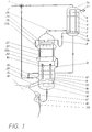
- the make-up water with subcooling of 18 K and more, is essentially heated in three stages. As shown in Fig. 1, the make-up water is fed via a feed line 2 to a 3-way valve 1 and there first divided into a smaller and a larger partial flow. The larger part of the make-up water comprises around 90% of the total flow and the smaller part accordingly around 10%.
- the smaller partial flow is fed to a vertically arranged capacitor stripper 3, which has two separate spatial areas.
- One area comprises two domes 3a, 3b which delimit the capacitor stripper at the top and bottom and which are closed and which are connected to one another via a vertical tube 4.
- the second room area is located between the closed domes 3a and 3b and is delimited by the apparatus inner wall of the capacitor stripper 3.
- the small partial flow is introduced into the upper dome 3a and flows in the vertically arranged bore 4 to the lower dome 3b.
- the tubing 4 is subjected to flushing steam in the opposite flow direction to the internally flowing make-up water.
- the flushing steam is enriched with inert gases from the make-up water. It flows through a steam inlet duct 7 above the lower dome 3b into the condenser stripper 3 and is driven by a suction unit 27 which is connected below the upper dome 3a to a suction nozzle 6 arranged there.
- the purge steam is almost completely condensed and separated from the inert gases. This process is reinforced by harassment 5 in the upper region of the capacitor stripper 3, that is to say in the vicinity of the upper dome 3a.
- the fully condensed purging vapor collects as condensate 8 above the dome 3b and the inert gases with a small residual vapor content are removed from the system by the suction unit 27.
- the rinsing steam advantageously remains in the water-steam circuit, the make-up water in the tube 4 is heated, and the suction unit 4 remains virtually unaffected by the steam volume flow.
- the preheated smaller substream of the make-up water is now fed back to the larger substream at a mixing point 28.
- the entire make-up water then flows through an inlet connector 10 into a likewise vertically arranged apparatus which has three areas over its vertical longitudinal extent.
- the lower part is designed as a steam inflow chamber 14 which closes at the bottom with a dome.
- the cathedral acts here as a collecting vessel 16 for heated and degassed make-up water.
- This tube 13 connects the lower steam inflow chamber 14 to a packing column 23 which is arranged above the tubular film heat exchanger 11 and is surrounded by a jacket film heat exchanger 22.
- the total flow of make-up water preheated by the partial flow thus flows through the inlet connector 10 on the casing side of the pipe 13 into the tubular film heat exchanger 11.
- the make-up water flows from the one at the bottom
- the last heating stage for make-up water takes place in the already mentioned jacket film heat exchanger 22, which is connected above the tubular film heat exchanger 11.
- the make-up water flows out of the outlet port 21 through a line first into a lower collecting ring channel 22a belonging to the jacket film heat exchanger 22.
- the make-up water is driven through a gap of 4 to 7 mm to an upper collecting ring channel 22b, with heat being transferred from the jacketed packing column 23 to the jacket film heat exchanger 22.
- This step completes the heating of the make-up water.
- the make-up water is now approximately saturated, i.e.
- the temperature delta between the exhaust steam from the condenser and the heated make-up water is only about 0.5 K taking into account the steam-side pressure losses.
- the degassing of the heated make-up water begins with the fact that - the make-up water by means of a spray device 24 which with is connected to the upper collecting ring channel 22b, is sprayed in above the packing column 23 and is thereby degassed by means of spontaneous expansion.
- condensate 8 is sprayed in from the condenser stripper 3 via the spray device via a condensate drain 9.
- the make-up water trickling from above and the exhaust steam flowing from below meet in the packing column 23. In this way, the material kinetic degassing is initiated and maintained.
- the state of saturation of the make-up water enables the dissolved inert gases to be easily expelled, as already discussed at the beginning.
- the packing column Since the packing column is used exclusively according to its function as a degasser, its diameter and packing volume are to be dimensioned comparatively significantly smaller than in apparatuses in which the packing column is to both heat and degas. In terms of volume, the packing column used here is approximately 75% smaller than a packing column for a forced double function. Such a smaller packing column is of course correspondingly cheaper, the risk of flooding, as can occur when packing columns with supercooled make-up water, is completely eliminated.
- the additional water trickling out of the packing column and here partially degassed is then heated again by means of a film dispensing device 20 via a tube falling film in the tube 13 by means of steam, since it has emitted thermal energy in the packing column 23.
- the make-up water heated in the tube falling film is first collected in the dome of the steam inflow chamber 14. From there, the make-up water is fed to a trough 17 on a condenser wall, which then supplies the make-up water to the condenser condensate along a falling film by means of a film dispenser 18.
- This measure results in the final degassing of the make-up water, which now has a characteristic O 2 concentration of about 5 ppb, taking into account that all other dissolved gases, such as N 2 , CO 2 , etc., have also been driven off.
- the exhaust steam coming from the condenser and used for heating and degassing carries all the expelled gases with it through a steam line into the condenser stripper.
- the expelled gases and the purge steam are separated here by condensation, which is used at the same time for heating supercooled make-up water.
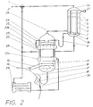
- FIG. 2 A second embodiment according to the invention is shown in FIG. 2.
- the essential difference compared to the first embodiment is the method for heating.
- the heating of the make-up water is carried out here essentially in an additional tube bundle 29 of the condenser 19, with which the tube film heat exchanger 11 is replaced.
- This tube bundle 29 can be implemented here as an integrated component of the condenser tubing.
- the cooling water used in a condenser 19 generally has a straightness of 2 to 3 K with respect to the evaporation temperature on the outflow side. Since the additional water supplied to the additional tube bundle 29 is 2 to 3 K warmer than cooling water, this additional water has approximately the desired saturation on the outflow side.
- the warming-up according to this second exemplary embodiment can, however, preferably only be used when planning a new system, whereas the first exemplary embodiment according to FIG. 1 can also be used in existing power plant systems.
- a decisive advantage of the designs according to the invention is that, despite the large amount of make-up water through optimized use of the heating and degassing measures and by combining suitable apparatus, only one suction unit 27 is required to provide the required driving potential.
- the invention is not limited to the exemplary embodiment shown and described. According to the invention, a combination of the heating by means of tube bundle 29 and tube falling film heat exchanger 11 is also conceivable, for example, a substitution of the packing column in FIG. 2 by a falling film gasifier would also be a variant according to the invention.
Landscapes
- Chemical & Material Sciences (AREA)
- Chemical Kinetics & Catalysis (AREA)
- Degasification And Air Bubble Elimination (AREA)
Applications Claiming Priority (2)
| Application Number | Priority Date | Filing Date | Title |
|---|---|---|---|
| DE19549139A DE19549139A1 (de) | 1995-12-29 | 1995-12-29 | Verfahren und Apparateanordnung zur Aufwärmung und mehrstufigen Entgasung von Wasser |
| DE19549139 | 1995-12-29 |
Publications (3)
| Publication Number | Publication Date |
|---|---|
| EP0781583A2 true EP0781583A2 (fr) | 1997-07-02 |
| EP0781583A3 EP0781583A3 (fr) | 1998-01-21 |
| EP0781583B1 EP0781583B1 (fr) | 2003-07-23 |
Family
ID=7781641
Family Applications (1)
| Application Number | Title | Priority Date | Filing Date |
|---|---|---|---|
| EP96810832A Expired - Lifetime EP0781583B1 (fr) | 1995-12-29 | 1996-11-28 | Procédé et dispositif de chauffage et de déaération multiple de l'eau |
Country Status (5)
| Country | Link |
|---|---|
| US (2) | US5930998A (fr) |
| EP (1) | EP0781583B1 (fr) |
| AU (1) | AU696041B2 (fr) |
| DE (2) | DE19549139A1 (fr) |
| ES (1) | ES2205010T3 (fr) |
Cited By (4)
| Publication number | Priority date | Publication date | Assignee | Title |
|---|---|---|---|---|
| EP0933109A3 (fr) * | 1998-01-28 | 1999-12-15 | OTTO HEAT Heizungs-, Energie- und Anlagentechnik GmbH & Co., KG | Dispositif pour le dégazage de milieux liquides |
| DE19924853A1 (de) * | 1999-05-31 | 2000-12-07 | Asea Brown Boveri | Kondensatormodul-System mit einer Apparateanordnung zum Aufwärmen und Entgasen von Zusatzwasser |
| EP1095686A1 (fr) * | 1999-10-29 | 2001-05-02 | Voith Paper Patent GmbH | Procédé et dispositif pour le désaérage d'une suspension de pâte à papier |
| CN119164216A (zh) * | 2024-11-22 | 2024-12-20 | 安徽盛特环境科技有限公司 | 一种有色冶炼烟气制酸的低温余热回收系统 |
Families Citing this family (13)
| Publication number | Priority date | Publication date | Assignee | Title |
|---|---|---|---|---|
| US6372699B1 (en) * | 1997-12-22 | 2002-04-16 | Kurita Water Industries Ltd. | Cleaning solution for electronic materials and method for using same |
| FI106296B (fi) | 1998-11-09 | 2001-01-15 | Amsco Europ Inc Suomen Sivulii | Menetelmä ja laite haihdutettavan veden käsittelemiseksi |
| RU2182116C1 (ru) * | 2001-06-05 | 2002-05-10 | Ульяновский государственный технический университет | Способ термической деаэрации воды |
| RU2183196C1 (ru) * | 2001-06-05 | 2002-06-10 | Ульяновский государственный технический университет | Деаэрационная установка |
| US6619042B2 (en) * | 2001-10-01 | 2003-09-16 | Holtec International, Inc. | Deaeration of makeup water in a steam surface condenser |
| RU2197433C1 (ru) * | 2002-01-08 | 2003-01-27 | Ульяновский государственный технический университет | Вакуумная деаэрационная установка |
| RU2210542C1 (ru) * | 2002-01-08 | 2003-08-20 | Ульяновский государственный технический университет | Способ термической деаэрации воды |
| DE10245935A1 (de) * | 2002-09-30 | 2004-05-19 | Alstom (Switzerland) Ltd. | Entlüftungs-/Entgasungssystem für Kraftwerkskondensatoren |
| DE10302870B3 (de) * | 2003-01-28 | 2004-08-05 | Stabilus Gmbh | Verstellvorrichtung |
| DE102005040380B3 (de) * | 2005-08-25 | 2006-07-27 | Gea Energietechnik Gmbh | Kondensationsverfahren |
| CN103988640A (zh) * | 2014-05-22 | 2014-08-20 | 孙明芹 | 一种秸秆还田机构下方的托叉 |
| DE102014217280A1 (de) * | 2014-08-29 | 2016-03-03 | Siemens Aktiengesellschaft | Verfahren und Anordnung einer Dampfturbinenanlage in Kombination mit einer thermischen Wasseraufbereitung |
| CN106195997A (zh) * | 2016-08-25 | 2016-12-07 | 中国五环工程有限公司 | 合成氨装置余热回收工艺方法及其系统 |
Family Cites Families (26)
| Publication number | Priority date | Publication date | Assignee | Title |
|---|---|---|---|---|
| DE957948C (de) * | 1957-01-24 | LICENTIA Patent-Verwaltungs-G mbH, Hamburg | Dampfkraftanlage mit Mischvorwarmer und turbmenangetriebenen Pumpen | |
| DE1110615B (de) * | 1956-05-12 | 1961-07-13 | Friedrich Johswich Dr Ing | Verfahren und Vorrichtung zur thermischen Entgasung von Fluessigkeiten durch Entspannung |
| US3330980A (en) * | 1965-07-16 | 1967-07-11 | Rca Corp | Shadow mask mounted with bi-metallic sections connected by expansible loop |
| US3803846A (en) * | 1971-06-14 | 1974-04-16 | S Letvin | Waste heat recovery process |
| AT374903B (de) * | 1975-10-23 | 1984-06-12 | Waagner Biro Ag | Einrichtung zur mischentgasung von fluessigkeiten |
| US4969507A (en) * | 1977-06-30 | 1990-11-13 | Rosenblad Axel E | Integral blow down concentrator with air-cooled surface condenser |
| US4241585A (en) * | 1978-04-14 | 1980-12-30 | Foster Wheeler Energy Corporation | Method of operating a vapor generating system having integral separators and a constant pressure furnace circuitry |
| US4288989A (en) * | 1979-02-05 | 1981-09-15 | Cassidy James L | Method and apparatus for obtaining mechanical energy from low temperature heat sources |
| SU1000717A1 (ru) * | 1981-05-21 | 1983-02-28 | Предприятие П/Я Г-4841 | Пленочный теплообменник |
| CH665451A5 (de) * | 1983-07-19 | 1988-05-13 | Bbc Brown Boveri & Cie | Verfahren zum reinigen und entgasen des kondensates/speisewassers im kreislauf einer stromerzeugungsanlage. |
| JPS60169084A (ja) * | 1984-02-14 | 1985-09-02 | Hitachi Ltd | 復水器の脱気方法と装置 |
| SE452745B (sv) * | 1984-04-24 | 1987-12-14 | Ahlstroem Foeretagen | Fallfilmsforangare av vertikalrorstyp |
| US4552099A (en) * | 1984-10-25 | 1985-11-12 | Westinghouse Electric Corp. | Anticipatory boiler feedpump suction head controller system |
| DE3662612D1 (en) * | 1985-09-20 | 1989-05-03 | Bbc Brown Boveri & Cie | Device for degassing the condensate in the circuit of an electricity power unit |
| US4683025A (en) * | 1986-02-10 | 1987-07-28 | The Graver Company | Method and apparatus to convert a long tube vertical evaporator to a falling film evaporator |
| DE3719861C2 (de) * | 1986-08-20 | 1988-08-04 | Koerting Ag | Dampfturbinenanlage |
| DE3709652A1 (de) * | 1987-03-24 | 1988-10-06 | Thermo Consulting Heidelberg | Vorrichtung zum verdampfen von fluessigkeiten bzw. absorbieren oder entgasen von zwei- oder mehrstoff-loesungen in innenrohr-fallfilm-bauweise |
| US4819436A (en) * | 1988-05-26 | 1989-04-11 | General Electric Company | Deaerator pressure control system |
| HUT47173A (en) * | 1988-08-19 | 1990-01-30 | Energiagazdalkodasi Intezet | Apparatus for replacing the feedwater of power plant |
| US4873829A (en) * | 1988-08-29 | 1989-10-17 | Williamson Anthony R | Steam power plant |
| CH682982A5 (de) * | 1990-06-11 | 1993-12-31 | Asea Brown Boveri | Apparat zur Aufwärmung und Entgasung von Wasser. |
| DE4022544A1 (de) * | 1990-07-16 | 1992-01-23 | Siemens Ag | Verfahren und anordnung zum entgasen eines kondensats |
| US5165237A (en) * | 1991-03-08 | 1992-11-24 | Graham Corporation | Method and apparatus for maintaining a required temperature differential in vacuum deaerators |
| US5246541A (en) * | 1991-05-14 | 1993-09-21 | A. Ahlstrom Corporation | Evaporator for liquid solutions |
| EP0561012B1 (fr) * | 1992-03-16 | 1996-05-29 | Asea Brown Boveri Ag | Procédé et dispositif pour le traitement d'eau dans un condensateur à surface |
| DE19513204A1 (de) * | 1995-04-11 | 1996-10-17 | Abb Management Ag | Apparat zur Aufwärmung und Entgasung von Wasser |
-
1995
- 1995-12-29 DE DE19549139A patent/DE19549139A1/de not_active Ceased
-
1996
- 1996-11-28 DE DE59610617T patent/DE59610617D1/de not_active Expired - Lifetime
- 1996-11-28 ES ES96810832T patent/ES2205010T3/es not_active Expired - Lifetime
- 1996-11-28 EP EP96810832A patent/EP0781583B1/fr not_active Expired - Lifetime
- 1996-12-04 US US08/760,334 patent/US5930998A/en not_active Expired - Lifetime
- 1996-12-24 AU AU76450/96A patent/AU696041B2/en not_active Expired
-
1999
- 1999-06-21 US US09/336,734 patent/US6145315A/en not_active Expired - Lifetime
Non-Patent Citations (1)
| Title |
|---|
| None |
Cited By (5)
| Publication number | Priority date | Publication date | Assignee | Title |
|---|---|---|---|---|
| EP0933109A3 (fr) * | 1998-01-28 | 1999-12-15 | OTTO HEAT Heizungs-, Energie- und Anlagentechnik GmbH & Co., KG | Dispositif pour le dégazage de milieux liquides |
| DE19924853A1 (de) * | 1999-05-31 | 2000-12-07 | Asea Brown Boveri | Kondensatormodul-System mit einer Apparateanordnung zum Aufwärmen und Entgasen von Zusatzwasser |
| EP1095686A1 (fr) * | 1999-10-29 | 2001-05-02 | Voith Paper Patent GmbH | Procédé et dispositif pour le désaérage d'une suspension de pâte à papier |
| US6425986B1 (en) | 1999-10-29 | 2002-07-30 | Voith Sulzer Papiertechnik Patent Gmbh | Process for degassing a paper stock suspension |
| CN119164216A (zh) * | 2024-11-22 | 2024-12-20 | 安徽盛特环境科技有限公司 | 一种有色冶炼烟气制酸的低温余热回收系统 |
Also Published As
| Publication number | Publication date |
|---|---|
| US6145315A (en) | 2000-11-14 |
| AU696041B2 (en) | 1998-08-27 |
| EP0781583A3 (fr) | 1998-01-21 |
| DE59610617D1 (de) | 2003-08-28 |
| DE19549139A1 (de) | 1997-07-03 |
| ES2205010T3 (es) | 2004-05-01 |
| EP0781583B1 (fr) | 2003-07-23 |
| AU7645096A (en) | 1997-02-27 |
| US5930998A (en) | 1999-08-03 |
Similar Documents
| Publication | Publication Date | Title |
|---|---|---|
| EP0781583B1 (fr) | Procédé et dispositif de chauffage et de déaération multiple de l'eau | |
| DE10330859A1 (de) | Verfahren zum Betrieb von emissionsfreien Gasturbinenkraftwerken | |
| DE2219650A1 (de) | Destillierverfahren und Vorrichtung zur Durchfuhrung des Verfahrens | |
| EP0461515B1 (fr) | Dispositif de chauffage et de dégazage de l'eau | |
| AT394100B (de) | Abhitze-dampferzeuger | |
| WO1997046304A1 (fr) | Procede et dispositif de sechage de gaz, notamment de gaz naturel | |
| EP0215230B1 (fr) | Dispositif de dégazage de condensat dans le circuit d'une unité de production d'électricité | |
| DE19544224B4 (de) | Chemische Fahrweise eines Wasser/Dampf-Kreislaufes | |
| EP0894948A1 (fr) | Centrale combinée à gaz et à vapeur avec générateur de vapeur à passage unique | |
| DE69520366T2 (de) | Verfahren zur abschliessenden eindampfung von schwarzlauge | |
| EP1425079B1 (fr) | Procede et dispositif de degazage thermique de la substance active d'un processus a deux phases | |
| EP0619466B1 (fr) | Condenseur de vapeur | |
| EP0425941B1 (fr) | Dispositif de dégazage et de chauffage d'eau | |
| EP0463448B1 (fr) | Procédé et dispositif de chauffage et de dégazage à multiple effet de l'eau | |
| EP0867214A2 (fr) | Dispositif pour le chauffage et le dégazage de l'eau | |
| DE4230266A1 (de) | Verfahren und Vorrichtung zur Wärmerückgewinnung beim chemischen Abbau von Klärschlamm oder Abwasser | |
| EP1576331B1 (fr) | Condenseur avec systeme de deaeration/degazage pour centrale thermique | |
| DE3133803C2 (de) | Verfahren zum Konzentrieren wässriger Lösungen von Glykolen durch Multieffekt-Destillation | |
| DE2717505A1 (de) | Zweistufiger verdampfer | |
| DE3838932C1 (en) | Process and plant for the physical refining of edible oils, fats and esters | |
| EP0737500A2 (fr) | Dispositif de chauffage et de dégazage de l'eau | |
| DE19848748A1 (de) | Verfahren zum Anfahren eines Dampfsystems und Dampfsystem zur Durchführung des Verfahrens | |
| DE3323120C2 (de) | Verfahren und Anlage zum Desodorieren und/oder Entsäuern von Cacaobutter und Cacaobutter-Ersatzstoffen | |
| DE3236985C2 (fr) | ||
| EP1249662B1 (fr) | Générateur de vapeur |
Legal Events
| Date | Code | Title | Description |
|---|---|---|---|
| PUAI | Public reference made under article 153(3) epc to a published international application that has entered the european phase |
Free format text: ORIGINAL CODE: 0009012 |
|
| AK | Designated contracting states |
Kind code of ref document: A2 Designated state(s): BE DE ES FR IT NL |
|
| PUAL | Search report despatched |
Free format text: ORIGINAL CODE: 0009013 |
|
| AK | Designated contracting states |
Kind code of ref document: A3 Designated state(s): BE DE ES FR IT NL |
|
| 17P | Request for examination filed |
Effective date: 19980702 |
|
| 17Q | First examination report despatched |
Effective date: 20010427 |
|
| RAP1 | Party data changed (applicant data changed or rights of an application transferred) |
Owner name: ALSTOM |
|
| RAP1 | Party data changed (applicant data changed or rights of an application transferred) |
Owner name: ALSTOM (SWITZERLAND) LTD |
|
| GRAH | Despatch of communication of intention to grant a patent |
Free format text: ORIGINAL CODE: EPIDOS IGRA |
|
| GRAH | Despatch of communication of intention to grant a patent |
Free format text: ORIGINAL CODE: EPIDOS IGRA |
|
| GRAA | (expected) grant |
Free format text: ORIGINAL CODE: 0009210 |
|
| AK | Designated contracting states |
Designated state(s): BE DE ES FR IT NL |
|
| PG25 | Lapsed in a contracting state [announced via postgrant information from national office to epo] |
Ref country code: FR Free format text: LAPSE BECAUSE OF FAILURE TO SUBMIT A TRANSLATION OF THE DESCRIPTION OR TO PAY THE FEE WITHIN THE PRESCRIBED TIME-LIMIT Effective date: 20030723 |
|
| REF | Corresponds to: |
Ref document number: 59610617 Country of ref document: DE Date of ref document: 20030828 Kind code of ref document: P |
|
| PG25 | Lapsed in a contracting state [announced via postgrant information from national office to epo] |
Ref country code: BE Free format text: LAPSE BECAUSE OF NON-PAYMENT OF DUE FEES Effective date: 20031130 |
|
| REG | Reference to a national code |
Ref country code: ES Ref legal event code: FG2A Ref document number: 2205010 Country of ref document: ES Kind code of ref document: T3 |
|
| PLBE | No opposition filed within time limit |
Free format text: ORIGINAL CODE: 0009261 |
|
| STAA | Information on the status of an ep patent application or granted ep patent |
Free format text: STATUS: NO OPPOSITION FILED WITHIN TIME LIMIT |
|
| BERE | Be: lapsed |
Owner name: *ALSTOM (SWITZERLAND) LTD Effective date: 20031130 |
|
| 26N | No opposition filed |
Effective date: 20040426 |
|
| EN | Fr: translation not filed | ||
| REG | Reference to a national code |
Ref country code: NL Ref legal event code: SD Effective date: 20120709 |
|
| REG | Reference to a national code |
Ref country code: DE Ref legal event code: R082 Ref document number: 59610617 Country of ref document: DE Representative=s name: UWE ROESLER, DE |
|
| REG | Reference to a national code |
Ref country code: ES Ref legal event code: PC2A Owner name: ALSTOM TECHNOLOGY LTD. Effective date: 20120814 |
|
| REG | Reference to a national code |
Ref country code: DE Ref legal event code: R082 Ref document number: 59610617 Country of ref document: DE Representative=s name: RUEGER, BARTHELT & ABEL, DE Effective date: 20120713 Ref country code: DE Ref legal event code: R082 Ref document number: 59610617 Country of ref document: DE Representative=s name: ROESLER, UWE, DIPL.-PHYS.UNIV., DE Effective date: 20120713 Ref country code: DE Ref legal event code: R081 Ref document number: 59610617 Country of ref document: DE Owner name: GENERAL ELECTRIC TECHNOLOGY GMBH, CH Free format text: FORMER OWNER: ALSTOM (SWITZERLAND) LTD., BADEN, CH Effective date: 20120713 Ref country code: DE Ref legal event code: R081 Ref document number: 59610617 Country of ref document: DE Owner name: ALSTOM TECHNOLOGY LTD., CH Free format text: FORMER OWNER: ALSTOM (SWITZERLAND) LTD., BADEN, CH Effective date: 20120713 |
|
| PGFP | Annual fee paid to national office [announced via postgrant information from national office to epo] |
Ref country code: IT Payment date: 20151125 Year of fee payment: 20 Ref country code: DE Payment date: 20151119 Year of fee payment: 20 |
|
| PGFP | Annual fee paid to national office [announced via postgrant information from national office to epo] |
Ref country code: ES Payment date: 20151111 Year of fee payment: 20 Ref country code: NL Payment date: 20151118 Year of fee payment: 20 |
|
| REG | Reference to a national code |
Ref country code: DE Ref legal event code: R082 Ref document number: 59610617 Country of ref document: DE Representative=s name: RUEGER ABEL PATENTANWAELTE PARTGMBB, DE Ref country code: DE Ref legal event code: R082 Ref document number: 59610617 Country of ref document: DE Representative=s name: RUEGER, BARTHELT & ABEL, DE |
|
| REG | Reference to a national code |
Ref country code: NL Ref legal event code: HC Owner name: GENERAL ELECTRIC TECHNOLOGY GMBH; CH Free format text: DETAILS ASSIGNMENT: VERANDERING VAN EIGENAAR(S), VERANDERING VAN NAAM VAN DE EIGENAAR(S); FORMER OWNER NAME: ALSTOM TECHNOLOGY LTD Effective date: 20160623 |
|
| REG | Reference to a national code |
Ref country code: DE Ref legal event code: R082 Ref document number: 59610617 Country of ref document: DE Representative=s name: RUEGER, BARTHELT & ABEL, DE Ref country code: DE Ref legal event code: R081 Ref document number: 59610617 Country of ref document: DE Owner name: GENERAL ELECTRIC TECHNOLOGY GMBH, CH Free format text: FORMER OWNER: ALSTOM TECHNOLOGY LTD., BADEN, CH |
|
| REG | Reference to a national code |
Ref country code: ES Ref legal event code: PC2A Owner name: GENERAL ELECTRIC TECHNOLOGY GMBH Effective date: 20161013 |
|
| REG | Reference to a national code |
Ref country code: DE Ref legal event code: R071 Ref document number: 59610617 Country of ref document: DE |
|
| REG | Reference to a national code |
Ref country code: NL Ref legal event code: MK Effective date: 20161127 |
|
| REG | Reference to a national code |
Ref country code: ES Ref legal event code: FD2A Effective date: 20170306 |
|
| PG25 | Lapsed in a contracting state [announced via postgrant information from national office to epo] |
Ref country code: ES Free format text: LAPSE BECAUSE OF EXPIRATION OF PROTECTION Effective date: 20161129 |