EP0781596B1 - Passives akustisches Verfahren zur Überwachung der Einsatzeinspritzleitungen einer katalytischen Crackanlage - Google Patents
Passives akustisches Verfahren zur Überwachung der Einsatzeinspritzleitungen einer katalytischen Crackanlage Download PDFInfo
- Publication number
- EP0781596B1 EP0781596B1 EP96309165A EP96309165A EP0781596B1 EP 0781596 B1 EP0781596 B1 EP 0781596B1 EP 96309165 A EP96309165 A EP 96309165A EP 96309165 A EP96309165 A EP 96309165A EP 0781596 B1 EP0781596 B1 EP 0781596B1
- Authority
- EP
- European Patent Office
- Prior art keywords
- feed
- frp
- reactor
- feed riser
- riser
- Prior art date
- Legal status (The legal status is an assumption and is not a legal conclusion. Google has not performed a legal analysis and makes no representation as to the accuracy of the status listed.)
- Expired - Lifetime
Links
Images


Classifications
-
- B—PERFORMING OPERATIONS; TRANSPORTING
- B01—PHYSICAL OR CHEMICAL PROCESSES OR APPARATUS IN GENERAL
- B01J—CHEMICAL OR PHYSICAL PROCESSES, e.g. CATALYSIS OR COLLOID CHEMISTRY; THEIR RELEVANT APPARATUS
- B01J8/00—Chemical or physical processes in general, conducted in the presence of fluids and solid particles; Apparatus for such processes
- B01J8/18—Chemical or physical processes in general, conducted in the presence of fluids and solid particles; Apparatus for such processes with fluidised particles
- B01J8/1809—Controlling processes
-
- B—PERFORMING OPERATIONS; TRANSPORTING
- B01—PHYSICAL OR CHEMICAL PROCESSES OR APPARATUS IN GENERAL
- B01J—CHEMICAL OR PHYSICAL PROCESSES, e.g. CATALYSIS OR COLLOID CHEMISTRY; THEIR RELEVANT APPARATUS
- B01J8/00—Chemical or physical processes in general, conducted in the presence of fluids and solid particles; Apparatus for such processes
- B01J8/001—Controlling catalytic processes
-
- B—PERFORMING OPERATIONS; TRANSPORTING
- B01—PHYSICAL OR CHEMICAL PROCESSES OR APPARATUS IN GENERAL
- B01J—CHEMICAL OR PHYSICAL PROCESSES, e.g. CATALYSIS OR COLLOID CHEMISTRY; THEIR RELEVANT APPARATUS
- B01J8/00—Chemical or physical processes in general, conducted in the presence of fluids and solid particles; Apparatus for such processes
- B01J8/18—Chemical or physical processes in general, conducted in the presence of fluids and solid particles; Apparatus for such processes with fluidised particles
- B01J8/24—Chemical or physical processes in general, conducted in the presence of fluids and solid particles; Apparatus for such processes with fluidised particles according to "fluidised-bed" technique
- B01J8/26—Chemical or physical processes in general, conducted in the presence of fluids and solid particles; Apparatus for such processes with fluidised particles according to "fluidised-bed" technique with two or more fluidised beds, e.g. reactor and regeneration installations
-
- C—CHEMISTRY; METALLURGY
- C10—PETROLEUM, GAS OR COKE INDUSTRIES; TECHNICAL GASES CONTAINING CARBON MONOXIDE; FUELS; LUBRICANTS; PEAT
- C10G—CRACKING HYDROCARBON OILS; PRODUCTION OF LIQUID HYDROCARBON MIXTURES, e.g. BY DESTRUCTIVE HYDROGENATION, OLIGOMERISATION, POLYMERISATION; RECOVERY OF HYDROCARBON OILS FROM OIL-SHALE, OIL-SAND, OR GASES; REFINING MIXTURES MAINLY CONSISTING OF HYDROCARBONS; REFORMING OF NAPHTHA; MINERAL WAXES
- C10G11/00—Catalytic cracking, in the absence of hydrogen, of hydrocarbon oils
- C10G11/14—Catalytic cracking, in the absence of hydrogen, of hydrocarbon oils with preheated moving solid catalysts
- C10G11/18—Catalytic cracking, in the absence of hydrogen, of hydrocarbon oils with preheated moving solid catalysts according to the "fluidised-bed" technique
- C10G11/187—Controlling or regulating
-
- G—PHYSICS
- G01—MEASURING; TESTING
- G01P—MEASURING LINEAR OR ANGULAR SPEED, ACCELERATION, DECELERATION, OR SHOCK; INDICATING PRESENCE, ABSENCE, OR DIRECTION, OF MOVEMENT
- G01P13/00—Indicating or recording presence, absence, or direction, of movement
-
- G—PHYSICS
- G01—MEASURING; TESTING
- G01P—MEASURING LINEAR OR ANGULAR SPEED, ACCELERATION, DECELERATION, OR SHOCK; INDICATING PRESENCE, ABSENCE, OR DIRECTION, OF MOVEMENT
- G01P15/00—Measuring acceleration; Measuring deceleration; Measuring shock, i.e. sudden change of acceleration
-
- B—PERFORMING OPERATIONS; TRANSPORTING
- B01—PHYSICAL OR CHEMICAL PROCESSES OR APPARATUS IN GENERAL
- B01J—CHEMICAL OR PHYSICAL PROCESSES, e.g. CATALYSIS OR COLLOID CHEMISTRY; THEIR RELEVANT APPARATUS
- B01J2208/00—Processes carried out in the presence of solid particles; Reactors therefor
- B01J2208/00008—Controlling the process
- B01J2208/00017—Controlling the temperature
- B01J2208/00026—Controlling or regulating the heat exchange system
- B01J2208/00035—Controlling or regulating the heat exchange system involving measured parameters
- B01J2208/00088—Flow rate measurement
-
- Y—GENERAL TAGGING OF NEW TECHNOLOGICAL DEVELOPMENTS; GENERAL TAGGING OF CROSS-SECTIONAL TECHNOLOGIES SPANNING OVER SEVERAL SECTIONS OF THE IPC; TECHNICAL SUBJECTS COVERED BY FORMER USPC CROSS-REFERENCE ART COLLECTIONS [XRACs] AND DIGESTS
- Y10—TECHNICAL SUBJECTS COVERED BY FORMER USPC
- Y10T—TECHNICAL SUBJECTS COVERED BY FORMER US CLASSIFICATION
- Y10T436/00—Chemistry: analytical and immunological testing
- Y10T436/12—Condition responsive control
Definitions
- the present invention relates to a passive acoustics process to monitor the feed injection lines of a catalytic cracker.
- the catalytic cracking of heavy oils to produce gasoline is widely accepted as the most important and widely used refinery process for converting heavy oils into more valuable gasoline and lighter products.
- Cracking can be defined as the breakdown of higher molecularweight hydrocarbons to lighter components by the application of heat. Cracking in the presence of a suitable catalyst produces an improvement in yield and quality over simple thermal cracking.
- Catalytic cracking is a continuous fluid bed process where, at catalyst mass rates as high as 40 tons a minute, fresh catalyst is brought into contact with injected feed and subsequently separated as deactivated ("spent") catalyst from the gas stream of cracked hydrocarbons. This separation occurs in a fluidized bed reactor and stripper. The spent catalyst in then reactivated by oxidation of coke deposits in a fluid bed regenerator and returned to the injection zone as fresh catalyst.
- the transfer of catalyst particles between the fluidized bed of the regenerator and other parts of the system is through transfer lines where the particles are transported in high velocity gas streams.
- the most important of these transfer lines from the viewpoint of feed conversion and product yield is the feed riser.
- initial contact is made between the fresh catalyst and an injected stream of oil and steam and a complex physical/chemical process takes place which produces large quantities of gas due to: (1) oil vaporization on the hot catalyst and (2) catalytic and thermal cracking of light hydrocarbons from the more complex hydrocarbons in the injected oil.
- An Initial Injection Zone where oil is introduced, contacts the circulating fresh catalyst and is vaporized.
- the design and performance of feed nozzles that inject the two phase mixture of oil and steam into the catalyst stream is critical for the performance of this section as is the density and uniformity of the catalyst particles.
- An Intermediate Reaction Zone where the major part of the catalytic cracking reaction is carried out and whose function is to maintain good contact between feed and catalyst while avoiding excessive back mixing.
- a critical design parameter is the average catalyst velocity.
- a Final Transport Zone which has the function of cracking the remaining convertible material without re-cracking valuable products (such as gasoline) that have been produced in the intermediate section.
- Fluid bed catalytic cracking units are designed to run continuously over periods of many years between planned shut-downs for maintenance, design changes and repairs. Due to the large throughput of cat-crackers, even modest improvements in performance, if maintained through the run length, are converted into significant financial incentives.
- EP-A-0 385 789 describes the measurement of the flow anisotropy in a two-phase fluidized bed in which the particles are suspended in a fluid. The fluid moves through the bed, but the particles remain in suspension while the wall vibrations are measured. The particles in such a fluidized bed move about in the bed sometimes colliding with the bed walls. The normal momentum of particles impacting on the walls produces wall vibrations. This document, however, does not describe the measurement of velocity, density and flux of a flowing fluid/particle stream, especially in transfer lines.
- the present invention is a method for non-intrusively monitoring the chemical and physical processes associated with gas generation in the feed riser of a cat-cracker and the correlation of those changes in these processes to changes in the output product produced the cat-cracker. It utilizes signal processing equipment to measure RMS acceleration of the feed riser wall at different locations along the length of the feed riser at a particular time.
- RMS acceleration which means root mean square acceleration, is well known in the art, see U.S. 5,022,266.
- the measurements of the RMS wall accelerations at different places along the feed riser is used to define a feed riser profile (FRP), which may change with time (FRP(t)).
- the FRP is a set of RMS wall acceleration which can be directly correlated with the conversion of injected oil to lighter and more valuable products because these accelerations are related to the gas generation at the locations where the measurements take place.
- This system and method can be used as an on-line monitor of the performance of the injection and reaction zone of the fluid bed catalytic cracking unit. Changes in the RMS measurements may be used to alert the operator that the catalytic cracking unit is not operating at its optimum performance.
- the invention provides a method for (a) measuring wall vibrations along a feed riser at more than two positions, (b) determining RMS acceleration at each of said positions and generating a feed riser profile thereform, and (c) comparing said feed riser profile to a pre-determined initial feed riser profile obtained when said reactor is operating at the desired performance, to determine a change in reactor performance.
- the operator may then change the operating parameters of the reactor so as to restore the FRP back to the initial values.
- the reference FRP may be determined from the same reactor at an earlier time when the reactor is operating at its desired performance. Alternatively, the reference FRP may be determined from a similar reactor.
- the present invention is a process for the non-intrusive measurement and monitoring of the set of RMS accelerations which is denoted the feed riser profile, FRP, produced by the impact of solid particles against the riser wall during cracking of injected feed along the length of the cat-cracking feed riser.
- the invention supplies on-line data which can be directly correlated with the conversion of injected oil to lighter and more valuable products and hence can be used as an on-line monitor of the performance of the injection and reaction zone of the fluid bed catalytic cracking unit, and as a system for alerting the unit operator should the data indicate that the unit is not operating at its optimal conversion and yield.
- the process is intended to assist the operators of such units to optimize the performance of the unit and maintain the unit at its optimum point with respect to unanticipated changes in a critical component, in changes in feed oil, or in changes in catalyst.
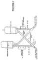
- Figure 1 shows a schematic of a catalytic cracking unit. Catalyst and injected oil are combined in the feed riser.
- a number of accelerometers are attached to the external wall of the feed riser from a location about 10 feet downstream of feed injection to a location 25 to 50 feet down stream of feed injection (see Figure 2). Inside this dimension about 8 accelerometer locations are chosen by examining the output of a magnetically attached accelerometer excited by an impact hammer (B & K 8202). Each accelerometer is at a specific axial distance from the feed injection point. The average RMS accelerations of each accelerometer at the location Z i from the oil injection point at time, t, is defined as A(t,Z i ).
- the set of values A(t,Z i ) along the feed riser, A(t,Z 1 ), A(t,Z 2 ),..., A(t,Z n ), corresponding to "n" measurement locations is defined as the Feed Riser Profile, FRP(t) at time, t.
- the FRP(t) will fall to a minimum value as gas generation falls off and then rise gradually as gas flow is channeled into increasing axial particle velocity.
- Figure 2 we indicate an arrangement of accelerometers and processing and computing units on the platform of the unit that convert the approximately 8 outputs of the accelerometers to a determination of the unit performance described below.
- each accelerometer is processed over a frequency band of width 2B centered on a central frequency, f o .
- the central frequency and bandwidth, 2B are chosen from an examination of the acceleration power spectra of the wall at the locations in question on the basis of the following criteria: (1) to include the localized wall resonance if it is a feature of the refractory steel wall in question; (2) to exclude extraneous sources of wall vibrational energy that are not associated with random catalyst particle impact; (3) to exclude spurious resonances such as mounting resonances of the accelerometer.
- the mean square acceleration at the time t 1 is determined and the square root of that quantity, which defines the RMS acceleration of the accelerometer in question, is obtained.
- the FRP(t), which are the values of A(t, z i ), may be fit to a continuous function in z at time, t.
- the operator of the unit may follow the change in unit performance by following the change in the FRP(t) or the changes in the five constants, C 1 to C 5 which make up the fit to the FRP(t).
- the electrical output of an array of accelerometers permanently mounted on the feed riser of a fluidized bed catalytic cracking unit is signal processed at the site to produce the FRP(t).
- the FRP(t) is fit to simple mathematical models and the magnitude of the fitting parameters transmitted to the control room of the catalytic cracking unit.
- a time average of the FRP(t) over a specified time interval is displayed as a reference (FRP ref ) as well as FRP(t) at later times.
- the variety of controls available to the operator over the units performance are adjusted by the operator to change its magnitude and shape of the FRP(t) - for example to maximize or broaden the peak, move it forward of the injection point in order to return the FRP(t) to its reference value.
- the FRP(t) can be maintained and restored by changes in a variety of parameters which are at the control of the operator. It should be noted that the change in some of these parameters induce change in others. Some examples are:
- the number of accelerometer locations required to define an FRP(t) that supplies useful process information to the operator depends on the unit and has to be determined empirically. As noted we have made the surprising discovery that the FRP(t) often exhibits gaussian dependence and can thus be approximated by a function that contains between 1 and 5 parameters, depending on the degree of accuracy. Thus 5 accelerometers covering three locations downstream of the peak and 2 upstream might be sufficient to determine a useful FRP(t).
- the following examples show how a library for the FRP(t) for a given reactor may be determined.
- This invention was used experimentally on the feed riser of a type A to show that the FRP is a stable characteristic of the feed riser that is well correlated with changes in feed riser performance due to routine process changes.
- the results of the tests appear in the first three rows of Table 1.
- Wall acceleration measurements were made at 15 different locations along the feed riser and an FRP(t) was computed.
- the arrangement of the sensors is shown schematically in Figure 2.
- Wall accelerations were measured with B&K model 4384 accelerometers and model 2635 charge amplifiers. All signals were simultaneously recorded by a RACAL multichannel tape recorder, and signal bandwidths were limited to the range of 6 to 10.9 KHz.
- the relative amount of feed injected through the lower and upper injector rings is one of the controls available to the FCCU operator. After adjustment feed conversion was restored to a normalized value of 1.00 and the FRP returned to its reference profile. This test illustrates that changes in the FRP, which are reflected in changes in the fitting parameters shown in Table 1, are well correlated with changes in unit performance.
- This FCCU is equipped with two types of feed injector nozzles, X and Y.
- the relative amount of feed injected into the feed riser through each injector nozzle is another control the FCCU operator can adjust in order to optimize operation of the unit.
- the nozzle configuration consisted of 2X and 6Y nozzles.
- the operator restored the FCCU to optimum operation by configuring the FCCU so that all the feed would be injected into the feed riser through the 8 type X nozzles.
- FIG. 5 shows the values of the wall acceleration and FRP that is obtained in the case when injector nozzle configuration is adjusted for maximum normalized feed conversion compared with the reference FRP.
- the changes in the fitting parameters used to compute the FRP are shown in the third row of Table 1, which also shows the large change in feed conversion.
- a comparison between the first and third rows of Table 1 shows that the FRP fitting parameters are well correlated with normalized feed conversion.
- measurement of the RMS acceleration at one location is sufficient to indicate changes in unit performance.
- a reference FRP was established, by the method described above as mode 1, during a period of good feed conversion. A period of time later the FCCU was observed to be operating in such away as to produce poor feed conversion. Measurement of the FRP fitting parameters permitted the operator to adjust the relative amount of feed injected through the two available nozzle types, X and Y, in such a way that the unit was brought back into proper operation as indicated by both measurements of product yield and by comparison of the resulting FRP fitting parameters with the reference FRP fitting parameters taken earlier.
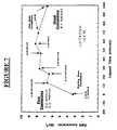
- Figure 6 shows how the measured wall acceleration changed 3 feet upstream of the type X nozzles during the time period in which the feed was changed from the 6 type Y + 2X nozzles to the 8X nozzles.
- FIG. 7 shows that the wall acceleration increase in magnitude 14.2 feet downstream of the type X nozzles for the change was accompanied by a reduction in wall acceleration of almost identical magnitude 3 feet upstream of the nozzles during the same time period of 70 minutes.
- the correlation between the wall acceleration at these positions and feed conversion shows that by carefully selecting the accelerometer position, the number of accelerometers can be reduced to as few as one or two.
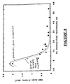
- FIG 8. Another example of the use of this invention is shown in figure 8.
- the invention was used to establish a reference FRP during a period of good conversion as measured by on-line product analysis.
- Row 4 of Table 1 contains the conversion obtained in the base case feed riser configuration, and the parameters used to generate the reference FRP fitting function.
- Injector nozzle balance is another control the FCCU operator can use to optimize the unit's operation.
- Row 5 of Table 1 shows that the improvement in conversion that accrues when the injector nozzles are balanced is correlated with the changes in the FRP, in figure 8, and in the fitting parameters, row 6 of Table 1.
- row 7 of Table 1 shows the RMS acceleration before adjustment of the nozzle balance and the solid curve shows the RMS acceleration after nozzle balance.
- Spent catalyst residence time is another control available to an FCCU operator. Residence time conditions were held constant and then adjusted for a period of time so that the extent of the response of the FRP to this process change could be measured.
- Figure 9 shows the reference FRP obtained for the FCCU in base case operation. Feed conversion, normalized to 1.00, and the FRP fitting parameters for the reference FRP are shown in row 4 of Table 1. A period of time later, the FCCU was observed to be operating with poor feed conversion. The FRP changed significantly from the reference FRP during this period.
Landscapes
- Chemical & Material Sciences (AREA)
- Chemical Kinetics & Catalysis (AREA)
- Organic Chemistry (AREA)
- Engineering & Computer Science (AREA)
- General Physics & Mathematics (AREA)
- Physics & Mathematics (AREA)
- Combustion & Propulsion (AREA)
- Oil, Petroleum & Natural Gas (AREA)
- General Chemical & Material Sciences (AREA)
- Production Of Liquid Hydrocarbon Mixture For Refining Petroleum (AREA)
- Devices And Processes Conducted In The Presence Of Fluids And Solid Particles (AREA)
- Low-Molecular Organic Synthesis Reactions Using Catalysts (AREA)
- Monitoring And Testing Of Nuclear Reactors (AREA)
- Investigating Or Analyzing Non-Biological Materials By The Use Of Chemical Means (AREA)
- Physical Or Chemical Processes And Apparatus (AREA)
Claims (9)
- Verfahren zur Überwachung der Leistung eines katalytischen Reaktors, bei dem(a) Wandvibrationen entlang eines Einsatzmaterial-Risers an mehr als zwei Positionen gemessen werden, (b) die RMS- Beschleunigung an jeder der Positionen bestimmt und daraus ein Einsatzmaterial-Riser-Profil generiert wird und (c) das Einsatzmaterial-Riser-Profil mit einem festgelegten Anfangs-Einsatzmaterial-Riser-Profil verglichen wird, das erhalten wird, wenn der Reaktor mit der gewünschten Leistung fährt, um eine Änderung der Reaktorleistung zu bestimmen.
- Verfahren nach Anspruch 1, bei dem das festgelegte Einsatzmaterial-Riser-Profil an dem Reaktor zu einem früheren Zeitpunkt bestimmt wurde.
- Verfahren nach Anspruch 1, bei dem das festgelegte Einsatzmaterial-Riser-Profil an einem ähnlichen Reaktor zu einem früheren Zeitpunkt bestimmt wurde.
- Verfahren nach einem der vorhergehenden Ansprüche, bei dem weiterhin ein oder mehrere Betriebsparameter des Reaktors geändert werden, um ihn zu dem Anfangs-Einsatzmaterial-Riser-Profil zurückzubringen.
- Verfahren zur Überwachung der Leistung eines katalytischen Reaktors, bei dem:(a) Wandvibrationen entlang eines Einsatzmaterial-Risers an mehr als zwei Positionen gemessen werden,(b) die Anfangs-RMS-Beschleunigung an jeder der Positionen bestimmt wird, wenn der Reaktor mit der gewünschten Leistung fährt, und daraus ein Anfangs-Einsatzmaterial-Riser-Profil generiert wird,(c) zu einem späteren Zeitpunkt eine zweite RMS-Beschleunigung an jeder der Positionen bestimmt und daraus ein zweites Einsatzmaterial-Riser-Profil generiert wird,(d) ein oder mehrere Betriebsparameter des Reaktors geändert werden, um das zweite Einsatzmaterial-Riser-Profil zu dem Anfangs-Einsatzmaterial-Riser-Profil zurückzubringen.
- Verfahren nach Anspruch 4 oder 5, bei dem der eine oder die mehreren Betriebsparameter die Einsatzmaterialtemperatur, die Gaseinspritzung, das Kat/Öl-Verhältnis, die Gasoberflächengeschwindigkeit, die Dampfkomponente der Düsen, das Einspritzmuster der Einsatzmaterialdüsen, die Kokszusammensetzung am Katalysator, Änderungen am Katalysator und Änderungen des Katalysators umfassen.
- Verfahren nach einem der vorhergehenden Ansprüche, bei dem Wandvibrationen an mehr als drei Positionen gemessen werden und einer stetigen Funktion der Position entlang des Risers mit vier Parametern genügen.
- Verfahren nach einem der Ansprüche 1 bis 6, bei dem Wandvibrationen an mehr als vier Positionen gemessen werden und einer stetigen Funktion der Position entlang des Risers mit fünf Parametern genügen.
- Verfahren nach Anspruch 7 oder Anspruch 8, bei dem die stetige Funktion die Summe einer Gauss- und einer linearen Funktion, mit dem Exponenten 3/2, ist.
Applications Claiming Priority (2)
| Application Number | Priority Date | Filing Date | Title |
|---|---|---|---|
| US577657 | 1995-12-22 | ||
| US08/577,657 US5652145A (en) | 1995-12-22 | 1995-12-22 | Passive acoustics process to monitor feed injection lines of a catalytic cracker (law077) |
Publications (3)
| Publication Number | Publication Date |
|---|---|
| EP0781596A2 EP0781596A2 (de) | 1997-07-02 |
| EP0781596A3 EP0781596A3 (de) | 1998-05-13 |
| EP0781596B1 true EP0781596B1 (de) | 2002-04-17 |
Family
ID=24309625
Family Applications (1)
| Application Number | Title | Priority Date | Filing Date |
|---|---|---|---|
| EP96309165A Expired - Lifetime EP0781596B1 (de) | 1995-12-22 | 1996-12-16 | Passives akustisches Verfahren zur Überwachung der Einsatzeinspritzleitungen einer katalytischen Crackanlage |
Country Status (8)
| Country | Link |
|---|---|
| US (1) | US5652145A (de) |
| EP (1) | EP0781596B1 (de) |
| JP (1) | JPH09189711A (de) |
| AU (1) | AU706734B2 (de) |
| CA (1) | CA2190771A1 (de) |
| CO (1) | CO4600609A1 (de) |
| DE (1) | DE69620725T2 (de) |
| ES (1) | ES2175042T3 (de) |
Families Citing this family (37)
| Publication number | Priority date | Publication date | Assignee | Title |
|---|---|---|---|---|
| US8512525B2 (en) * | 2001-03-12 | 2013-08-20 | Curtiss-Wright Flow Control Corporation | Valve system and method for unheading a coke drum |
| US8123197B2 (en) | 2001-03-12 | 2012-02-28 | Curtiss-Wright Flow Control Corporation | Ethylene production isolation valve systems |
| US8702911B2 (en) | 2003-02-21 | 2014-04-22 | Curtiss-Wright Flow Control Corporation | Center feed system |
| US7316762B2 (en) | 2003-04-11 | 2008-01-08 | Curtiss-Wright Flow Control Corporation | Dynamic flange seal and sealing system |
| US7117959B2 (en) * | 2004-04-22 | 2006-10-10 | Curtiss-Wright Flow Control Corporation | Systems and methods for remotely determining and changing cutting modes during decoking |
| US8679298B2 (en) | 2004-04-22 | 2014-03-25 | Curtiss-Wright Flow Control Corporation | Remotely controlled decoking tool used in coke cutting operations |
| US7473337B2 (en) * | 2004-04-22 | 2009-01-06 | Curtiss-Wright Flow Control Corporation | Remotely controlled decoking tool used in coke cutting operations |
| US20070038393A1 (en) * | 2005-08-12 | 2007-02-15 | Frederic Borah | Vibration monitoring |
| US7819009B2 (en) * | 2006-02-28 | 2010-10-26 | Frederic Borah | Vibration Monitoring System |
| US7931044B2 (en) | 2006-03-09 | 2011-04-26 | Curtiss-Wright Flow Control Corporation | Valve body and condensate holding tank flushing systems and methods |
| US20080314413A1 (en) * | 2007-06-20 | 2008-12-25 | Exxonmobil Research And Engineering Company | Cyclone cleaning device and method |
| US8440057B2 (en) | 2008-01-23 | 2013-05-14 | Curtiss-Wright Flow Control Corporation | Linked coke drum support |
| US7871500B2 (en) | 2008-01-23 | 2011-01-18 | Curtiss-Wright Flow Control Corporation | Coke drum skirt |
| US10239034B2 (en) | 2009-02-06 | 2019-03-26 | Marathon Petroleum Company Lp | FCC cyclone using acoustic detectors |
| US8545680B2 (en) * | 2009-02-11 | 2013-10-01 | Curtiss-Wright Flow Control Corporation | Center feed system |
| US8851451B2 (en) * | 2009-03-23 | 2014-10-07 | Curtiss-Wright Flow Control Corporation | Non-rising electric actuated valve operator |
| US8459608B2 (en) | 2009-07-31 | 2013-06-11 | Curtiss-Wright Flow Control Corporation | Seat and valve systems for use in delayed coker system |
| US9146169B2 (en) * | 2012-11-26 | 2015-09-29 | General Electric Company | Method and system for use in condition monitoring of pressure vessels |
| US10696906B2 (en) | 2017-09-29 | 2020-06-30 | Marathon Petroleum Company Lp | Tower bottoms coke catching device |
| US12000720B2 (en) | 2018-09-10 | 2024-06-04 | Marathon Petroleum Company Lp | Product inventory monitoring |
| US12031676B2 (en) | 2019-03-25 | 2024-07-09 | Marathon Petroleum Company Lp | Insulation securement system and associated methods |
| US11975316B2 (en) | 2019-05-09 | 2024-05-07 | Marathon Petroleum Company Lp | Methods and reforming systems for re-dispersing platinum on reforming catalyst |
| CA3212045A1 (en) | 2019-05-30 | 2020-11-30 | Marathon Petroleum Company Lp | Methods and systems for minimizing nox and co emissions in natural draft heaters |
| CA3109606C (en) | 2020-02-19 | 2022-12-06 | Marathon Petroleum Company Lp | Low sulfur fuel oil blends for paraffinic resid stability and associated methods |
| US11702600B2 (en) | 2021-02-25 | 2023-07-18 | Marathon Petroleum Company Lp | Assemblies and methods for enhancing fluid catalytic cracking (FCC) processes during the FCC process using spectroscopic analyzers |
| US12461022B2 (en) | 2021-02-25 | 2025-11-04 | Marathon Petroleum Company Lp | Methods and assemblies for determining and using standardized spectral responses for calibration of spectroscopic analyzers |
| US11905468B2 (en) | 2021-02-25 | 2024-02-20 | Marathon Petroleum Company Lp | Assemblies and methods for enhancing control of fluid catalytic cracking (FCC) processes using spectroscopic analyzers |
| US12473500B2 (en) | 2021-02-25 | 2025-11-18 | Marathon Petroleum Company Lp | Assemblies and methods for enhancing control of fluid catalytic cracking (FCC) processes using spectroscopic analyzers |
| US11898109B2 (en) | 2021-02-25 | 2024-02-13 | Marathon Petroleum Company Lp | Assemblies and methods for enhancing control of hydrotreating and fluid catalytic cracking (FCC) processes using spectroscopic analyzers |
| US20250012744A1 (en) | 2021-02-25 | 2025-01-09 | Marathon Petroleum Company Lp | Methods and assemblies for enhancing control of refining processes using spectroscopic analyzers |
| US11692141B2 (en) | 2021-10-10 | 2023-07-04 | Marathon Petroleum Company Lp | Methods and systems for enhancing processing of hydrocarbons in a fluid catalytic cracking unit using a renewable additive |
| US11802257B2 (en) | 2022-01-31 | 2023-10-31 | Marathon Petroleum Company Lp | Systems and methods for reducing rendered fats pour point |
| US12311305B2 (en) | 2022-12-08 | 2025-05-27 | Marathon Petroleum Company Lp | Removable flue gas strainer and associated methods |
| US12306076B2 (en) | 2023-05-12 | 2025-05-20 | Marathon Petroleum Company Lp | Systems, apparatuses, and methods for sample cylinder inspection, pressurization, and sample disposal |
| US12533615B2 (en) | 2023-06-02 | 2026-01-27 | Marathon Petroleum Company Lp | Methods and systems for reducing contaminants in a feed stream |
| US12415962B2 (en) | 2023-11-10 | 2025-09-16 | Marathon Petroleum Company Lp | Systems and methods for producing aviation fuel |
| US12599848B2 (en) | 2024-06-03 | 2026-04-14 | Marathon Petroleum Company Lp | Systems, analyzers, controllers, and associated methods to enhance fluid separation for distillation operations |
Family Cites Families (11)
| Publication number | Priority date | Publication date | Assignee | Title |
|---|---|---|---|---|
| US3012848A (en) * | 1958-11-12 | 1961-12-12 | Jr Ralph P Levey | Method for sensing degree of fluidization in a fluidized bed |
| US3553636A (en) * | 1969-01-27 | 1971-01-05 | Bindicator Co | Noncontact ultrasonic interface viscosity and percent solid detecting device |
| US4357603A (en) * | 1980-11-24 | 1982-11-02 | The United States Of America As Represented By The Depart Of Energy | Method and apparatus for acoustically monitoring the flow of suspended solid particulate matter |
| US4650566A (en) | 1984-05-30 | 1987-03-17 | Mobil Oil Corporation | FCC reactor multi-feed nozzle system |
| US4808383A (en) | 1985-05-30 | 1989-02-28 | Mobil Oil Corporation | FCC reactor multi-feed nozzle system |
| US4824016A (en) * | 1987-12-10 | 1989-04-25 | Exxon Research And Engineering Company | Acoustic monitoring of two phase feed nozzles |
| US5022266A (en) * | 1989-03-02 | 1991-06-11 | Exxon Research And Engineering Company | Passive acoustics process to monitor fluidized bed flow |
| US5022268A (en) * | 1989-05-22 | 1991-06-11 | Exxon Research And Engineering Company | Passive acoustics system to monitor fluidized bed systems |
| GB9014251D0 (en) * | 1990-06-27 | 1990-08-15 | British Petroleum Co Plc | Method for monitoring acoustic emissions |
| EP0499759A1 (de) * | 1991-02-21 | 1992-08-26 | Bp Chemicals S.N.C. | Verfahren zur Überwachung der Strömung in einem pneumatischen Fördersystem |
| US5353627A (en) * | 1993-08-19 | 1994-10-11 | Texaco Inc. | Passive acoustic detection of flow regime in a multi-phase fluid flow |
-
1995
- 1995-12-22 US US08/577,657 patent/US5652145A/en not_active Expired - Fee Related
-
1996
- 1996-11-19 CA CA002190771A patent/CA2190771A1/en not_active Abandoned
- 1996-12-16 ES ES96309165T patent/ES2175042T3/es not_active Expired - Lifetime
- 1996-12-16 EP EP96309165A patent/EP0781596B1/de not_active Expired - Lifetime
- 1996-12-16 DE DE69620725T patent/DE69620725T2/de not_active Expired - Fee Related
- 1996-12-18 CO CO96066464A patent/CO4600609A1/es unknown
- 1996-12-19 AU AU75476/96A patent/AU706734B2/en not_active Ceased
- 1996-12-24 JP JP8355671A patent/JPH09189711A/ja active Pending
Also Published As
| Publication number | Publication date |
|---|---|
| EP0781596A2 (de) | 1997-07-02 |
| DE69620725D1 (de) | 2002-05-23 |
| DE69620725T2 (de) | 2002-11-28 |
| AU7547696A (en) | 1997-06-26 |
| AU706734B2 (en) | 1999-06-24 |
| ES2175042T3 (es) | 2002-11-16 |
| US5652145A (en) | 1997-07-29 |
| CA2190771A1 (en) | 1997-06-23 |
| JPH09189711A (ja) | 1997-07-22 |
| CO4600609A1 (es) | 1998-05-08 |
| EP0781596A3 (de) | 1998-05-13 |
Similar Documents
| Publication | Publication Date | Title |
|---|---|---|
| EP0781596B1 (de) | Passives akustisches Verfahren zur Überwachung der Einsatzeinspritzleitungen einer katalytischen Crackanlage | |
| EP0399796B1 (de) | Passives akustisches System für die Überwachung von Wirbelbettsystemen | |
| EP0385789B1 (de) | Passives akustisches Verfahren zur Überwachung der Strömung eines Wirbelbettes | |
| EP0385788B1 (de) | Passive akustische Methode zur Überwachung des Niveaus eines flüssigen Bettes | |
| EP0266192B1 (de) | Passive akustische Kraftspektra zur Überwachung und zum Kontrollieren von Prozessen | |
| JP2735103B2 (ja) | 2相供給ノズルの音響式監視 | |
| US4973386A (en) | Passive acoustic power spectra to monitor and control processing | |
| CA2192488A1 (en) | Passive acoustics process to monitor transfer lines of a reactor | |
| Cody et al. | A novel non-intrusive probe of particle motion and gas generation in the feed injection zone of the feed riser of a fluidized bed catalytic cracking unit | |
| Saxena et al. | Diagnostic procedures for establishing the quality of fluidization of gas-solid systems | |
| Aldugman et al. | Comparative analysis of counter-current and co-current downer reactors using particle image velocimetry and computational particle-fluid dynamics | |
| Tafreshi et al. | Improving the efficiency of fluid cokers by altering two-phase feed characteristics | |
| Dodge | Representation of average drop sizes in sprays | |
| Sobocinski et al. | New fiber-optic method for measuring velocities of strands and solids hold-up in gas-solids downflow reactors | |
| Pandey et al. | Nonintrusive particle motion studies in the near-wall region of a pilot-scale circulating fluidized bed | |
| Varghese et al. | Measurement of solids holdup in a gas–solid fluidized bed: an experimental, statistical and ANN approach | |
| Yuan et al. | Regime identification of gas–solid fluidized bed based on pressure pulsation signals by improved Hilbert-Huang transform | |
| Sauriol et al. | Gas–solid structure in the vicinity of a sparger nozzle in a fluidized bed | |
| Duan | Investigations of plasma instabilities in a spray torch | |
| Cartellier et al. | Dispersed phase measurements in sprays using optical probes | |
| Johnston | The Effects of Distributor Design on the Hydrodynarnics within the Entrance Region of a Cocurrent Downflow Circulating Fluidized Bed (Downer) Reactor | |
| Bielma et al. | Integrated workflow for optimizing the gas–solid fluidization in a diameter-transformed dense bed with Geldart A particles | |
| Congjing et al. | Online estimation of coke in a circulating fluidized bed based on acoustic emission sensors and multivariate calibration | |
| Holst et al. | Examination of the residence time distribution in a high pressure thermogravimetric system | |
| Toseland | Engineering development of slurry bubble column reactor (SBCR) technology. Quarterly report, October 1--December 31, 1995 |
Legal Events
| Date | Code | Title | Description |
|---|---|---|---|
| PUAI | Public reference made under article 153(3) epc to a published international application that has entered the european phase |
Free format text: ORIGINAL CODE: 0009012 |
|
| AK | Designated contracting states |
Kind code of ref document: A2 Designated state(s): DE ES FR GB IT NL |
|
| PUAL | Search report despatched |
Free format text: ORIGINAL CODE: 0009013 |
|
| AK | Designated contracting states |
Kind code of ref document: A3 Designated state(s): DE ES FR GB IT NL |
|
| 17P | Request for examination filed |
Effective date: 19981019 |
|
| 17Q | First examination report despatched |
Effective date: 20000112 |
|
| RAP1 | Party data changed (applicant data changed or rights of an application transferred) |
Owner name: EXXONMOBIL RESEARCH AND ENGINEERING COMPANY |
|
| GRAG | Despatch of communication of intention to grant |
Free format text: ORIGINAL CODE: EPIDOS AGRA |
|
| GRAG | Despatch of communication of intention to grant |
Free format text: ORIGINAL CODE: EPIDOS AGRA |
|
| GRAG | Despatch of communication of intention to grant |
Free format text: ORIGINAL CODE: EPIDOS AGRA |
|
| GRAH | Despatch of communication of intention to grant a patent |
Free format text: ORIGINAL CODE: EPIDOS IGRA |
|
| REG | Reference to a national code |
Ref country code: GB Ref legal event code: IF02 |
|
| GRAH | Despatch of communication of intention to grant a patent |
Free format text: ORIGINAL CODE: EPIDOS IGRA |
|
| GRAA | (expected) grant |
Free format text: ORIGINAL CODE: 0009210 |
|
| AK | Designated contracting states |
Kind code of ref document: B1 Designated state(s): DE ES FR GB IT NL |
|
| REF | Corresponds to: |
Ref document number: 69620725 Country of ref document: DE Date of ref document: 20020523 |
|
| ET | Fr: translation filed | ||
| REG | Reference to a national code |
Ref country code: ES Ref legal event code: FG2A Ref document number: 2175042 Country of ref document: ES Kind code of ref document: T3 |
|
| PLBE | No opposition filed within time limit |
Free format text: ORIGINAL CODE: 0009261 |
|
| STAA | Information on the status of an ep patent application or granted ep patent |
Free format text: STATUS: NO OPPOSITION FILED WITHIN TIME LIMIT |
|
| 26N | No opposition filed |
Effective date: 20030120 |
|
| PGFP | Annual fee paid to national office [announced via postgrant information from national office to epo] |
Ref country code: GB Payment date: 20031105 Year of fee payment: 8 |
|
| PGFP | Annual fee paid to national office [announced via postgrant information from national office to epo] |
Ref country code: NL Payment date: 20031110 Year of fee payment: 8 |
|
| PGFP | Annual fee paid to national office [announced via postgrant information from national office to epo] |
Ref country code: FR Payment date: 20031201 Year of fee payment: 8 |
|
| PGFP | Annual fee paid to national office [announced via postgrant information from national office to epo] |
Ref country code: ES Payment date: 20031212 Year of fee payment: 8 |
|
| PGFP | Annual fee paid to national office [announced via postgrant information from national office to epo] |
Ref country code: DE Payment date: 20031230 Year of fee payment: 8 |
|
| PG25 | Lapsed in a contracting state [announced via postgrant information from national office to epo] |
Ref country code: GB Free format text: LAPSE BECAUSE OF NON-PAYMENT OF DUE FEES Effective date: 20041216 |
|
| PG25 | Lapsed in a contracting state [announced via postgrant information from national office to epo] |
Ref country code: ES Free format text: LAPSE BECAUSE OF NON-PAYMENT OF DUE FEES Effective date: 20041217 |
|
| PG25 | Lapsed in a contracting state [announced via postgrant information from national office to epo] |
Ref country code: NL Free format text: LAPSE BECAUSE OF NON-PAYMENT OF DUE FEES Effective date: 20050701 Ref country code: DE Free format text: LAPSE BECAUSE OF NON-PAYMENT OF DUE FEES Effective date: 20050701 |
|
| GBPC | Gb: european patent ceased through non-payment of renewal fee |
Effective date: 20041216 |
|
| PG25 | Lapsed in a contracting state [announced via postgrant information from national office to epo] |
Ref country code: FR Free format text: LAPSE BECAUSE OF NON-PAYMENT OF DUE FEES Effective date: 20050831 |
|
| NLV4 | Nl: lapsed or anulled due to non-payment of the annual fee |
Effective date: 20050701 |
|
| REG | Reference to a national code |
Ref country code: FR Ref legal event code: ST |
|
| PG25 | Lapsed in a contracting state [announced via postgrant information from national office to epo] |
Ref country code: IT Free format text: LAPSE BECAUSE OF NON-PAYMENT OF DUE FEES;WARNING: LAPSES OF ITALIAN PATENTS WITH EFFECTIVE DATE BEFORE 2007 MAY HAVE OCCURRED AT ANY TIME BEFORE 2007. THE CORRECT EFFECTIVE DATE MAY BE DIFFERENT FROM THE ONE RECORDED. Effective date: 20051216 |
|
| REG | Reference to a national code |
Ref country code: ES Ref legal event code: FD2A Effective date: 20041217 |