EP0781701A2 - Fahrradsattel - Google Patents
Fahrradsattel Download PDFInfo
- Publication number
- EP0781701A2 EP0781701A2 EP96120972A EP96120972A EP0781701A2 EP 0781701 A2 EP0781701 A2 EP 0781701A2 EP 96120972 A EP96120972 A EP 96120972A EP 96120972 A EP96120972 A EP 96120972A EP 0781701 A2 EP0781701 A2 EP 0781701A2
- Authority
- EP
- European Patent Office
- Prior art keywords
- seat
- support
- steering support
- saddle
- saddle according
- Prior art date
- Legal status (The legal status is an assumption and is not a legal conclusion. Google has not performed a legal analysis and makes no representation as to the accuracy of the status listed.)
- Granted
Links
- 239000006260 foam Substances 0.000 claims abstract description 4
- 210000001217 buttock Anatomy 0.000 claims description 3
- 230000037396 body weight Effects 0.000 description 2
- 230000002349 favourable effect Effects 0.000 description 2
- 238000010276 construction Methods 0.000 description 1
- 230000003203 everyday effect Effects 0.000 description 1
- 230000005802 health problem Effects 0.000 description 1
- 238000004519 manufacturing process Methods 0.000 description 1
- 210000000689 upper leg Anatomy 0.000 description 1
Images
Classifications
-
- B—PERFORMING OPERATIONS; TRANSPORTING
- B62—LAND VEHICLES FOR TRAVELLING OTHERWISE THAN ON RAILS
- B62J—CYCLE SADDLES OR SEATS; AUXILIARY DEVICES OR ACCESSORIES SPECIALLY ADAPTED TO CYCLES AND NOT OTHERWISE PROVIDED FOR, e.g. ARTICLE CARRIERS OR CYCLE PROTECTORS
- B62J1/00—Saddles or other seats for cycles; Arrangement thereof; Component parts
- B62J1/002—Saddles having a seating area with a central cavity or depression
-
- B—PERFORMING OPERATIONS; TRANSPORTING
- B62—LAND VEHICLES FOR TRAVELLING OTHERWISE THAN ON RAILS
- B62J—CYCLE SADDLES OR SEATS; AUXILIARY DEVICES OR ACCESSORIES SPECIALLY ADAPTED TO CYCLES AND NOT OTHERWISE PROVIDED FOR, e.g. ARTICLE CARRIERS OR CYCLE PROTECTORS
- B62J1/00—Saddles or other seats for cycles; Arrangement thereof; Component parts
- B62J1/14—Separate pillions
Definitions
- the invention relates to a saddle for two-wheelers, in particular bicycles, with a seat which is attached to the frame of the bicycle or the like by means of a height-adjustable frame.
- the invention is therefore based on the object of further developing a bicycle saddle in such a way that the distribution of the body weight is optimized and the lateral stability during the ride can be significantly improved by simple means.
- this object is achieved in that the seat has a wide support surface for the rider's buttocks and that in Direction of travel in front of the seat a steering column is attached, which is essentially at the height of the seat.
- the steering support can consist of an elongated body, the longitudinal extension of which is in the direction of travel.
- the steering support provided according to the invention is enclosed by the driver's two thighs during the ride, as a result of which they assume cornering forces and give the body on the seat a safe and rotation-free position without impairing the usual driving and steering feel on the bicycle.
- the overall system of two-wheeler drivers is given a directional stability which is substantially better than that of the prior art by the bicycle saddle designed according to the invention.
- the distance between the steering support and the seat is adjustable and can thus be adapted to the body size of the driver. It is also advantageous if the steering support can be pivoted about a horizontal axis, so that the height relative to the seat can also be adjusted to an optimal dimension.
- the seat has a recess in the middle of its front edge, which is anatomically very advantageous especially for male drivers and into which the steering support can be moved if necessary.
- a valve for introducing hard foam is provided on the underside of the seat in order to be able to select the hardness and elasticity of the seat in this way.
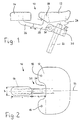
- the two figures show a saddle, designated overall by 10, for a two-wheeler, in particular a bicycle, which according to the invention consists of an elastic seat 12 and a steering support 14.
- the seat 12 has a much wider support surface in the manner of a chair than the conventional seats, on which the driver's buttocks rests.
- the seat 12 At its front edge, the seat 12 has a recess 34, so that the base of the seat 12 has approximately the shape of a U.
- the seat 12 is mounted at two points 18 lying symmetrically to the longitudinal axis 16 in the region of its front edge on a support frame 20 which is fastened in a known manner to a tube 22 of the frame in an adjustable manner.
- the rear part of the seat 12 is supported in the middle by a spring 24 on the support frame 20.
- the longitudinal support 14 is designed as an elongated body, the longitudinal extension of which lies in the direction of travel.
- the steering support 14 is attached at the upper end to an angle tube 26 which is attached to the front part 28 of the support frame 20.
- the angle tube 26 is attached to the front part 28 of the support frame 20, for example by a telescopic connection, so that the distance a between the steering support 14 and the seat 12th can be adjusted.
- This distance a is generally of the order of 80 mm.
- Figure 1 shows that a valve 32 is provided on the underside of the seat 12, through which rigid foam can be injected in order to be able to adjust the hardness and elasticity of the seat 12.
Landscapes
- Engineering & Computer Science (AREA)
- Mechanical Engineering (AREA)
- Automatic Cycles, And Cycles In General (AREA)
- Steering Devices For Bicycles And Motorcycles (AREA)
- Motorcycle And Bicycle Frame (AREA)
Abstract
Description
- Die Erfindung betrifft einen Sattel für Zweiräder, insbesondere Fahrräder, mit einem Sitz, der über einen Stützrahmen höhenverstellbar am Rahmen des Fahrrades oder dergleichen befestigt ist.
- Bekannte Konstruktionen eines derartigen Fahrradsattels haben den Nachteil, daß sich das Körpergewicht des Fahrers auf einer zu kleinen Sitzfläche abstützt. Ferner wird die Seitenstabilität während der Fahrt im wesentlichen nur über die Arme und den aufgrund seiner Drehbeweglichkeit instabilen Lenker bewirkt. Diese Nachteile sind insbesondere auf längeren Fahrten spürbar, und zwar sowohl bei der alltäglichen Verwendung des Fahrrades für Beruf und Freizeit als auch beim sportlichen Einsatz. Ermüdungserscheinungen, verminderte Verkehrssicherheit und gesundheitliche Beeinträchtigungen bei häufigem Gebrauch sind die Folgen.
- Der Erfindung liegt daher die Aufgabe zugrunde, einen Fahrradsattel so weiterzuentwickeln, daß die Verteilung des Körpergewichtes optimiert und die Seitenstabilität während der Fahrt mit einfachen Mitteln wesentlich verbessert werden.
- Bei einem Sattel der eingangs umrissenen Bauart wird diese Aufgabe erfindungsgemäß dadurch gelöst, daß der Sitz eine breite Abstützfläche für das Gesäß des Fahrers hat und daß in Fahrtrichtung vor dem Sitz eine Lenkstütze befestigt ist, die im wesentlichen in Höhe des Sitzes liegt.
- Durch die Aufteilung des Sattels in einen großflächigen, anpassungsfähigen Sitz und eine davon getrennte Lenkstütze werden eine wesentlich günstigere Gewichtsverteilung sowie ein besseres Lenkverhalten erreicht.
- Die Lenkstütze kann aus einem länglichen Körper bestehen, dessen Längserstreckung in Fahrtrichtung liegt.
- Die erfindungsgemäß vorgesehene Lenkstütze wird bei der Fahrt von den beiden Oberschenkeln des Fahrers umschlossen, wodurch sie Seitenführungskräfte übernehmen und dem Körper auf dem Sitz eine sichere und drehungsfreie Position verleihen, ohne daß das gewohnte Fahr- und Lenkgefühl auf dem Fahrrad beeinträchtigt wird. Dem Gesamtsystem Zweirad - Fahrer wird durch den erfindungsgemäß ausgebildeten Fahradsattel eine gegenüber dem Stand der Technik wesentlich bessere Richtungsstabilität verliehen.
- Es ist vorteilhaft, wenn die Lenkstütze am Stützrahmen des Sitzes angebracht ist, wodurch sich Herstellung und Montage sehr einfach gestalten.
- Nach einem bevorzugten Merkmal der Erfindung ist der Abstand zwischen der Lenkstütze und dem Sitz einstellbar und kann somit an die Körpermaße des jeweiligen Fahrers angepaßt werden. Ebenfalls ist es vorteilhaft, wenn die Lenkstütze um eine horizontale Achse verschwenkt werden kann, so daß auch die Höhe relativ zum Sitz auf ein optimales Maß eingestellt werden kann.
- Es ist besonders günstig, wenn der Sitz in der Mitte seiner Vorderkante eine Aussparung aufweist, die vor allem für männliche Fahrer anatomisch sehr vorteilhaft ist und in die bei Bedarf die Lenkstütze verschoben werden kann.
- Nach einem anderen Merkmal der Erfindung ist an der Unterseite des Sitzes ein Ventil zum Einbringen von Hartschaum vorgesehen, um auf diese Weise die Härte und Elastizität des Sitzes wählen zu können.
- Die Erfindung ist nachstehend an einem Ausführungsbeispiel erläutert, das in der Zeichnung dargestellt ist. Es zeigen:
- Figur 1 eine Seitenansicht eines Fahrradsattels gemäß der Erfindung und
- Figur 2 eine Draufsicht des in Figur 1 gezeigten Fahrradsattels.
- Die beiden Figuren zeigen einen insgesamt mit 10 bezeichneten Sattel für ein Zweirad, insbesondere ein Fahrrad, der gemäß der Erfindung aus einem elastischen Sitz 12 und einer Lenkstütze 14 besteht. Der Sitz 12 hat eine gegenüber herkömmlichen Sitzen wesentlich breitere Abstützfläche nach Art eines Stuhles, auf der das Gesäß des Fahrers ruht. An seiner Vorderkante hat der Sitz 12 eine Aussparung 34, so daß die Grundfläche des Sitzes 12 etwa die Form eines U aufweist. Der Sitz 12 ist an zwei symmetrisch zur Längsachse 16 liegenden Punkten 18 im Bereich seiner Vorderkante auf einem Stützrahmen 20 gelagert, welcher in bekannter Weise höhenverstellbar auf einem Rohr 22 des Rahmens befestigt ist. Der hintere Teil des Sitzes 12 stützt sich in der Mitte über eine Feder 24 auf dem Stützrahmen 20 ab.
- Wie insbesonder Figur 2 zeigt, ist die Längsstütze 14 als ein länglicher Körper ausgebildet, dessen Längserstreckung in Fahrtrichtung liegt. Die Lenkstütze 14 ist am oberen Ende auf einem Winkelrohr 26 befestigt, das am vorderen Teil 28 des Stützrahmen 20 befestigt ist. In Figur 1 ist angedeutet, daß es günstig ist, wenn das Winkelrohr 26 beispielsweise durch eine Teleskopverbindung am vorderen Teil 28 des Stützrahmens 20 angebracht ist, so daß der Abstand a zwischen der Lenkstütze 14 und dem Sitz 12 eingestellt werden kann. Dieser Abstand a liegt im allgemeinen in der Größenordnung von 80 mm.
- In Figur 1 ist ferner zu erkennen, daß der vordere Teil 28 des Stützrahmens 20 um eine horizontale Achse 30 verschwenkt werden kann, so daß auch die Höhe der Lenkstütze 14 relativ zum Sitz 12 in gewissen Grenzen eingestellt werden kann.
- Figur 1 zeigt, daß an der Unterseite des Sitzes 12 ein Ventil 32 vorgesehen ist, über welches Hartschaum eingespritzt werden kann, um die Härte und Elastizität des Sitzes 12 einstellen zu können.
- Versuche haben ergeben, daß als optimale Abmessungen für die Lenkstütze 14 eine Länge 1 von etwa 120 mm und eine Breite b von etwa 50 m gewählt werden können.
Claims (7)
- Sattel für Zweiräder, insbesondere Fahrräder, mit einem Sitz (12), der über einen Stützrahmen (20) höhenverstellbar am Rahmen des Fahrrades oder dergleichen befestigt ist, dadurch gekennzeichnet, daß der Sitz (12) eine breite Abstützfläche für das Gesäß des Fahrers hat und daß in Fahrtrichtung vor dem Sitz (12) eine Lenkstütze (14) befestigt ist, die im wesentlichen in Höhe des Sitzes (12) liegt.
- Sattel nach Anspruch 1, dadurch gekennzeichnet, daß die Lenkstütze (14) aus einem länglichen Körper besteht, dessen Längserstreckung in Fahrtrichtung liegt.
- Sattel nach Anspruch 1 oder 2, dadurch gekennzeichnet, daß die Lenkstütze (14) am Stützrahmen (20) des Sitzes (12) angebracht ist.
- Sattel nach einem der vorhergehenden Ansprüche, dadurch gekennzeichnet, daß der Abstand (a) zwischen der Lenkstütze (14) und dem Sitz (12) einstellbar ist.
- Sattel nach einem der vorhergehenden Ansprüche, dadurch gekennzeichnet, daß die Lenkstütze (14) um eine horizontale Achse (30) schwenkbar ist.
- Sattel nach einem der vorhergehenden Ansprüche, dadurch gekennzeichnet, daß der Sitz (12) in der Mitte seiner Vorderkante eine Aussparung (34) aufweist.
- Sattel nach einem der vorhergehenden Ansprüche, dadurch gekennzeichnet, daß an der Unterseite des Sitzes (12) ein Ventil (32) zum Einbringen von Hartschaum vorgesehen ist.
Applications Claiming Priority (2)
| Application Number | Priority Date | Filing Date | Title |
|---|---|---|---|
| DE29520715U DE29520715U1 (de) | 1995-12-30 | 1995-12-30 | Fahrradsattel-zweigeteilt- in Sitz- und Lenkteil |
| DE29520715U | 1995-12-30 |
Publications (3)
| Publication Number | Publication Date |
|---|---|
| EP0781701A2 true EP0781701A2 (de) | 1997-07-02 |
| EP0781701A3 EP0781701A3 (de) | 1998-08-26 |
| EP0781701B1 EP0781701B1 (de) | 2002-02-27 |
Family
ID=8017361
Family Applications (1)
| Application Number | Title | Priority Date | Filing Date |
|---|---|---|---|
| EP96120972A Expired - Lifetime EP0781701B1 (de) | 1995-12-30 | 1996-12-28 | Fahrradsattel |
Country Status (2)
| Country | Link |
|---|---|
| EP (1) | EP0781701B1 (de) |
| DE (2) | DE29520715U1 (de) |
Cited By (2)
| Publication number | Priority date | Publication date | Assignee | Title |
|---|---|---|---|---|
| EP1980476A1 (de) * | 2004-09-01 | 2008-10-15 | RTI Sports Vertrieb von Sportartikeln GmbH | Fahrradsattel |
| BE1018142A3 (nl) * | 2007-10-05 | 2010-06-01 | D En G Projects | Fietszadel, stuurmiddelen voor een fietszadel en een fiets voorzien van een fietszadel. |
Families Citing this family (3)
| Publication number | Priority date | Publication date | Assignee | Title |
|---|---|---|---|---|
| DE19834903C2 (de) * | 1998-01-19 | 2000-04-06 | Lothar Jander | Fahrradsattel |
| EP1057721B1 (de) * | 1999-06-02 | 2005-10-05 | Kenji Tsuge | Fahrradsattelvorrichtung |
| DE19932031B4 (de) * | 1999-07-09 | 2006-11-23 | Rolf Harle | Fahrradsattel |
Family Cites Families (6)
| Publication number | Priority date | Publication date | Assignee | Title |
|---|---|---|---|---|
| BE509115A (de) * | ||||
| US3970345A (en) * | 1975-07-11 | 1976-07-20 | Holcomb Stephen A | Cycle seat with accessory-bearing attachments |
| AT366972B (de) * | 1980-01-03 | 1982-05-25 | Fuchs Erwin | Vorrichtung an faehrraedern, insbesondere sportoder rennraedern |
| DE3625210A1 (de) * | 1986-07-25 | 1988-02-04 | Wendel Verlag Gmbh & Co Kg | Fahrradsattel |
| US5123698A (en) * | 1990-10-25 | 1992-06-23 | Martec Development, Inc. | Bicycle seat with adjustable support platforms |
| DE9414922U1 (de) * | 1994-09-14 | 1994-12-15 | Harling, Hans, 53773 Hennef | Luftkissenauflage für Fahrradsattel |
-
1995
- 1995-12-30 DE DE29520715U patent/DE29520715U1/de not_active Expired - Lifetime
-
1996
- 1996-12-28 DE DE59608793T patent/DE59608793D1/de not_active Expired - Fee Related
- 1996-12-28 EP EP96120972A patent/EP0781701B1/de not_active Expired - Lifetime
Non-Patent Citations (1)
| Title |
|---|
| None |
Cited By (2)
| Publication number | Priority date | Publication date | Assignee | Title |
|---|---|---|---|---|
| EP1980476A1 (de) * | 2004-09-01 | 2008-10-15 | RTI Sports Vertrieb von Sportartikeln GmbH | Fahrradsattel |
| BE1018142A3 (nl) * | 2007-10-05 | 2010-06-01 | D En G Projects | Fietszadel, stuurmiddelen voor een fietszadel en een fiets voorzien van een fietszadel. |
Also Published As
| Publication number | Publication date |
|---|---|
| EP0781701B1 (de) | 2002-02-27 |
| DE29520715U1 (de) | 1996-05-02 |
| DE59608793D1 (de) | 2002-04-04 |
| EP0781701A3 (de) | 1998-08-26 |
Similar Documents
| Publication | Publication Date | Title |
|---|---|---|
| DE68917928T2 (de) | Anpassbarer lenkstangenschaft für ein fahrrad oder dergleichen. | |
| EP1454823B1 (de) | Sattel | |
| DE69013838T2 (de) | Träger- und sattelkombination. | |
| CH681879A5 (de) | ||
| EP0781701B1 (de) | Fahrradsattel | |
| EP0586754A1 (de) | Rahmen für einspurige Fahrzeuge, insbesondere Fahrräder | |
| DE19932031B4 (de) | Fahrradsattel | |
| DE29705494U1 (de) | Sport-Rollstuhl | |
| DE212008000106U1 (de) | Fahrrad- oder Trainingsradsitz | |
| WO2005032877A1 (de) | Mehrachsiges zweispuriges kraftfahrzeug | |
| DE3940166A1 (de) | Lenkbarer schneegleiter | |
| EP3369648A1 (de) | System für ein laufrad oder ein fahrrad sowie ein entsprechendes laufrad oder fahrrad | |
| DE20102680U1 (de) | Lenkstruktur für Roller | |
| DE3420351A1 (de) | Motorrad | |
| DE20006468U1 (de) | Fahrrad | |
| DE3906601A1 (de) | Zweirad mit sicherheitsrahmen | |
| DE110185C (de) | ||
| DE3934692A1 (de) | Anatomischer sitz, insbesondere fuer kraftfahrzeuge | |
| DE9103867U1 (de) | Fahrradrahmen | |
| DE29800418U1 (de) | Fahrradrahmen | |
| DE19901932A1 (de) | Anatomisch geformter Fahrradsattel | |
| DE102017127861A1 (de) | System für ein Laufrad oder ein Fahrrad sowie ein entsprechendes Laufrad oder Fahrrad | |
| AT201440B (de) | Lenkbarer Rodelschlitten | |
| DE3203941A1 (de) | Lenkvorrichtung fuer rodelschlitten | |
| DE9214531U1 (de) | Gefederte Lenkstange für Fahrräder |
Legal Events
| Date | Code | Title | Description |
|---|---|---|---|
| PUAI | Public reference made under article 153(3) epc to a published international application that has entered the european phase |
Free format text: ORIGINAL CODE: 0009012 |
|
| AK | Designated contracting states |
Kind code of ref document: A2 Designated state(s): DE FR IT |
|
| PUAL | Search report despatched |
Free format text: ORIGINAL CODE: 0009013 |
|
| AK | Designated contracting states |
Kind code of ref document: A3 Designated state(s): DE FR IT |
|
| 17P | Request for examination filed |
Effective date: 19990219 |
|
| 17Q | First examination report despatched |
Effective date: 19991019 |
|
| GRAG | Despatch of communication of intention to grant |
Free format text: ORIGINAL CODE: EPIDOS AGRA |
|
| GRAG | Despatch of communication of intention to grant |
Free format text: ORIGINAL CODE: EPIDOS AGRA |
|
| GRAH | Despatch of communication of intention to grant a patent |
Free format text: ORIGINAL CODE: EPIDOS IGRA |
|
| GRAH | Despatch of communication of intention to grant a patent |
Free format text: ORIGINAL CODE: EPIDOS IGRA |
|
| GRAA | (expected) grant |
Free format text: ORIGINAL CODE: 0009210 |
|
| AK | Designated contracting states |
Kind code of ref document: B1 Designated state(s): DE FR IT |
|
| REF | Corresponds to: |
Ref document number: 59608793 Country of ref document: DE Date of ref document: 20020404 |
|
| ET | Fr: translation filed | ||
| PLBE | No opposition filed within time limit |
Free format text: ORIGINAL CODE: 0009261 |
|
| STAA | Information on the status of an ep patent application or granted ep patent |
Free format text: STATUS: NO OPPOSITION FILED WITHIN TIME LIMIT |
|
| 26N | No opposition filed |
Effective date: 20021128 |
|
| PG25 | Lapsed in a contracting state [announced via postgrant information from national office to epo] |
Ref country code: FR Free format text: LAPSE BECAUSE OF NON-PAYMENT OF DUE FEES Effective date: 20030901 |
|
| REG | Reference to a national code |
Ref country code: FR Ref legal event code: ST |
|
| PGFP | Annual fee paid to national office [announced via postgrant information from national office to epo] |
Ref country code: DE Payment date: 20050121 Year of fee payment: 9 |
|
| PG25 | Lapsed in a contracting state [announced via postgrant information from national office to epo] |
Ref country code: IT Free format text: LAPSE BECAUSE OF NON-PAYMENT OF DUE FEES Effective date: 20051228 |
|
| PG25 | Lapsed in a contracting state [announced via postgrant information from national office to epo] |
Ref country code: DE Free format text: LAPSE BECAUSE OF NON-PAYMENT OF DUE FEES Effective date: 20060701 |