EP0781892B1 - Automatische Schiebetür mit mindestens einem Flügel - Google Patents
Automatische Schiebetür mit mindestens einem Flügel Download PDFInfo
- Publication number
- EP0781892B1 EP0781892B1 EP96119999A EP96119999A EP0781892B1 EP 0781892 B1 EP0781892 B1 EP 0781892B1 EP 96119999 A EP96119999 A EP 96119999A EP 96119999 A EP96119999 A EP 96119999A EP 0781892 B1 EP0781892 B1 EP 0781892B1
- Authority
- EP
- European Patent Office
- Prior art keywords
- thrust rod
- sliding door
- automatic sliding
- push rod
- principal
- Prior art date
- Legal status (The legal status is an assumption and is not a legal conclusion. Google has not performed a legal analysis and makes no representation as to the accuracy of the status listed.)
- Expired - Lifetime
Links
Images


Classifications
-
- E—FIXED CONSTRUCTIONS
- E05—LOCKS; KEYS; WINDOW OR DOOR FITTINGS; SAFES
- E05F—DEVICES FOR MOVING WINGS INTO OPEN OR CLOSED POSITION; CHECKS FOR WINGS; WING FITTINGS NOT OTHERWISE PROVIDED FOR, CONCERNED WITH THE FUNCTIONING OF THE WING
- E05F15/00—Power-operated mechanisms for wings
- E05F15/70—Power-operated mechanisms for wings with automatic actuation
- E05F15/72—Power-operated mechanisms for wings with automatic actuation responsive to emergency conditions, e.g. fire
-
- E—FIXED CONSTRUCTIONS
- E05—LOCKS; KEYS; WINDOW OR DOOR FITTINGS; SAFES
- E05F—DEVICES FOR MOVING WINGS INTO OPEN OR CLOSED POSITION; CHECKS FOR WINGS; WING FITTINGS NOT OTHERWISE PROVIDED FOR, CONCERNED WITH THE FUNCTIONING OF THE WING
- E05F15/00—Power-operated mechanisms for wings
- E05F15/60—Power-operated mechanisms for wings using electrical actuators
- E05F15/603—Power-operated mechanisms for wings using electrical actuators using rotary electromotors
- E05F15/632—Power-operated mechanisms for wings using electrical actuators using rotary electromotors for horizontally-sliding wings
- E05F15/643—Power-operated mechanisms for wings using electrical actuators using rotary electromotors for horizontally-sliding wings operated by flexible elongated pulling elements, e.g. belts, chains or cables
-
- E—FIXED CONSTRUCTIONS
- E05—LOCKS; KEYS; WINDOW OR DOOR FITTINGS; SAFES
- E05F—DEVICES FOR MOVING WINGS INTO OPEN OR CLOSED POSITION; CHECKS FOR WINGS; WING FITTINGS NOT OTHERWISE PROVIDED FOR, CONCERNED WITH THE FUNCTIONING OF THE WING
- E05F1/00—Closers or openers for wings, not otherwise provided for in this subclass
- E05F1/08—Closers or openers for wings, not otherwise provided for in this subclass spring-actuated, e.g. for horizontally sliding wings
- E05F1/16—Closers or openers for wings, not otherwise provided for in this subclass spring-actuated, e.g. for horizontally sliding wings for sliding wings
-
- E—FIXED CONSTRUCTIONS
- E05—LOCKS; KEYS; WINDOW OR DOOR FITTINGS; SAFES
- E05Y—INDEXING SCHEME ASSOCIATED WITH SUBCLASSES E05D AND E05F, RELATING TO CONSTRUCTION ELEMENTS, ELECTRIC CONTROL, POWER SUPPLY, POWER SIGNAL OR TRANSMISSION, USER INTERFACES, MOUNTING OR COUPLING, DETAILS, ACCESSORIES, AUXILIARY OPERATIONS NOT OTHERWISE PROVIDED FOR, APPLICATION THEREOF
- E05Y2201/00—Constructional elements; Accessories therefor
- E05Y2201/20—Brakes; Disengaging means; Holders; Stops; Valves; Accessories therefor
- E05Y2201/214—Disengaging means
- E05Y2201/216—Clutches
-
- E—FIXED CONSTRUCTIONS
- E05—LOCKS; KEYS; WINDOW OR DOOR FITTINGS; SAFES
- E05Y—INDEXING SCHEME ASSOCIATED WITH SUBCLASSES E05D AND E05F, RELATING TO CONSTRUCTION ELEMENTS, ELECTRIC CONTROL, POWER SUPPLY, POWER SIGNAL OR TRANSMISSION, USER INTERFACES, MOUNTING OR COUPLING, DETAILS, ACCESSORIES, AUXILIARY OPERATIONS NOT OTHERWISE PROVIDED FOR, APPLICATION THEREOF
- E05Y2201/00—Constructional elements; Accessories therefor
- E05Y2201/20—Brakes; Disengaging means; Holders; Stops; Valves; Accessories therefor
- E05Y2201/23—Actuation thereof
- E05Y2201/246—Actuation thereof by auxiliary motors, magnets, springs or weights
-
- E—FIXED CONSTRUCTIONS
- E05—LOCKS; KEYS; WINDOW OR DOOR FITTINGS; SAFES
- E05Y—INDEXING SCHEME ASSOCIATED WITH SUBCLASSES E05D AND E05F, RELATING TO CONSTRUCTION ELEMENTS, ELECTRIC CONTROL, POWER SUPPLY, POWER SIGNAL OR TRANSMISSION, USER INTERFACES, MOUNTING OR COUPLING, DETAILS, ACCESSORIES, AUXILIARY OPERATIONS NOT OTHERWISE PROVIDED FOR, APPLICATION THEREOF
- E05Y2201/00—Constructional elements; Accessories therefor
- E05Y2201/40—Motors; Magnets; Springs; Weights; Accessories therefor
- E05Y2201/404—Function thereof
- E05Y2201/422—Function thereof for opening
-
- E—FIXED CONSTRUCTIONS
- E05—LOCKS; KEYS; WINDOW OR DOOR FITTINGS; SAFES
- E05Y—INDEXING SCHEME ASSOCIATED WITH SUBCLASSES E05D AND E05F, RELATING TO CONSTRUCTION ELEMENTS, ELECTRIC CONTROL, POWER SUPPLY, POWER SIGNAL OR TRANSMISSION, USER INTERFACES, MOUNTING OR COUPLING, DETAILS, ACCESSORIES, AUXILIARY OPERATIONS NOT OTHERWISE PROVIDED FOR, APPLICATION THEREOF
- E05Y2201/00—Constructional elements; Accessories therefor
- E05Y2201/40—Motors; Magnets; Springs; Weights; Accessories therefor
- E05Y2201/46—Magnets
- E05Y2201/462—Electromagnets
-
- E—FIXED CONSTRUCTIONS
- E05—LOCKS; KEYS; WINDOW OR DOOR FITTINGS; SAFES
- E05Y—INDEXING SCHEME ASSOCIATED WITH SUBCLASSES E05D AND E05F, RELATING TO CONSTRUCTION ELEMENTS, ELECTRIC CONTROL, POWER SUPPLY, POWER SIGNAL OR TRANSMISSION, USER INTERFACES, MOUNTING OR COUPLING, DETAILS, ACCESSORIES, AUXILIARY OPERATIONS NOT OTHERWISE PROVIDED FOR, APPLICATION THEREOF
- E05Y2201/00—Constructional elements; Accessories therefor
- E05Y2201/40—Motors; Magnets; Springs; Weights; Accessories therefor
- E05Y2201/47—Springs
- E05Y2201/478—Gas springs
-
- E—FIXED CONSTRUCTIONS
- E05—LOCKS; KEYS; WINDOW OR DOOR FITTINGS; SAFES
- E05Y—INDEXING SCHEME ASSOCIATED WITH SUBCLASSES E05D AND E05F, RELATING TO CONSTRUCTION ELEMENTS, ELECTRIC CONTROL, POWER SUPPLY, POWER SIGNAL OR TRANSMISSION, USER INTERFACES, MOUNTING OR COUPLING, DETAILS, ACCESSORIES, AUXILIARY OPERATIONS NOT OTHERWISE PROVIDED FOR, APPLICATION THEREOF
- E05Y2201/00—Constructional elements; Accessories therefor
- E05Y2201/40—Motors; Magnets; Springs; Weights; Accessories therefor
- E05Y2201/47—Springs
- E05Y2201/488—Traction springs
-
- E—FIXED CONSTRUCTIONS
- E05—LOCKS; KEYS; WINDOW OR DOOR FITTINGS; SAFES
- E05Y—INDEXING SCHEME ASSOCIATED WITH SUBCLASSES E05D AND E05F, RELATING TO CONSTRUCTION ELEMENTS, ELECTRIC CONTROL, POWER SUPPLY, POWER SIGNAL OR TRANSMISSION, USER INTERFACES, MOUNTING OR COUPLING, DETAILS, ACCESSORIES, AUXILIARY OPERATIONS NOT OTHERWISE PROVIDED FOR, APPLICATION THEREOF
- E05Y2800/00—Details, accessories and auxiliary operations not otherwise provided for
- E05Y2800/25—Emergency conditions
-
- E—FIXED CONSTRUCTIONS
- E05—LOCKS; KEYS; WINDOW OR DOOR FITTINGS; SAFES
- E05Y—INDEXING SCHEME ASSOCIATED WITH SUBCLASSES E05D AND E05F, RELATING TO CONSTRUCTION ELEMENTS, ELECTRIC CONTROL, POWER SUPPLY, POWER SIGNAL OR TRANSMISSION, USER INTERFACES, MOUNTING OR COUPLING, DETAILS, ACCESSORIES, AUXILIARY OPERATIONS NOT OTHERWISE PROVIDED FOR, APPLICATION THEREOF
- E05Y2800/00—Details, accessories and auxiliary operations not otherwise provided for
- E05Y2800/67—Materials; Strength alteration thereof
- E05Y2800/676—Plastics
- E05Y2800/678—Elastomers
-
- E—FIXED CONSTRUCTIONS
- E05—LOCKS; KEYS; WINDOW OR DOOR FITTINGS; SAFES
- E05Y—INDEXING SCHEME ASSOCIATED WITH SUBCLASSES E05D AND E05F, RELATING TO CONSTRUCTION ELEMENTS, ELECTRIC CONTROL, POWER SUPPLY, POWER SIGNAL OR TRANSMISSION, USER INTERFACES, MOUNTING OR COUPLING, DETAILS, ACCESSORIES, AUXILIARY OPERATIONS NOT OTHERWISE PROVIDED FOR, APPLICATION THEREOF
- E05Y2900/00—Application of doors, windows, wings or fittings thereof
- E05Y2900/10—Application of doors, windows, wings or fittings thereof for buildings or parts thereof
- E05Y2900/13—Type of wing
- E05Y2900/132—Doors
Definitions
- the invention relates to an automatic sliding door at least one wing according to the preamble of the claim 1.
- a generic automatic sliding door is out of the DE 44 00 940 C1 become known.
- the generic Sliding door is characterized in that the one door leaf load-bearing running device with a clutch is coupled to a driver and is separable from it through a commonly used circumferential belt is driven. About this driver and in normal operation closed coupling becomes the carriage device and thus the door leaves in their respective opening and closed position moves.
- the between the take-away and the Carriage device provided coupling automatically opened so that one with the entire arrangement with movable Auxiliary drive takes effect and the door, at now driver not moved due to power failure or immobile propulsion or transmission means, in the opening position is adjusted.
- This design principle is characterized in that the energy accumulator serving as an auxiliary drive as a rotating one Lift mechanism is designed. That is, in deviation from Solutions that became known even earlier are the energy accumulator always loaded. In other words, it has to be added to every new one Do not reload the door closing movement each time since during undisturbed operation when opening the Door wing also no mandatory discharge the lift mechanism is required.
- the embodiment described is a sliding door two carriages offset in the longitudinal direction hung on a rail arrangement and along it movable.
- a driving device and thus as a drive and link is another carriage intended.
- the sliding door according to the invention has compared to the previously known State of the art further significant advantages on.
- Push rod is used.
- Push rods are in themselves known in the art.
- the push rod assembly at least divided into two, preferably telescopic and between the two interacting parts the push rod assembly of the energy storage sits and is effective when needed.
- this can be designed in this way Push rod for wing doors of different sizes deploy.
- a push rod according to the invention can Gullwing doors with an opening width of 800 mm are no problem up to 2300 mm.
- Push rod assemblies also in themselves known energy store in the form of an elastomeric element, especially a rubber-elastic rope used. But also an energy store in the form of a compression spring, in particular gas pressure spring, is ultimately possible.
- the arrangement according to the invention makes it possible according to one Embodiment that the rubber-elastic energy storage element in rope form over the essential length of the push rod according to the invention, i.e. the push rod basic element, misplaced and at the front end of the with the Belt drive with movable push rod basic element is returned by deflection by 180 °.
- An enlargement the elastic force effect of the auxiliary drive thus formed can be achieved in that the rubber elastic Rope element is laid twice. It can be in one piece be designed so that the rubber-elastic element in the middle at the end of the preferably telescopic extendable push rod element attacks this and the wing door coupled with it, particularly in the case of abnormal operation opens.
- the rubber rope always with a separate rope monitoring device is monitored for its functionality. If out for some reason tear the rubber elastic rope or but through long-term use the rubber-elastic forces can fall below a minimum with the rubber rope monitoring also an automatic switch to Abnormal operation take place, combined with an automatic Open the corresponding wing door.
- the actual locking of the auxiliary drive mechanically takes place, whereas the triggering is magnetically effected becomes.
- the magnet only has to be used comparatively low forces are applied to the belay device to keep in normal operating position.
- a circuit supplying power to the magnet interrupted by operating a switch and the corresponding magnet can be switched off. Also this will immediately switch the assigned sliding door back in Move to the open position.
- Figures 1 and 2 is a schematic excerpt Representation of a sliding door with two sliding door leaves 1 shown, in Figure 1 in closed and in Figure 2 in the open position.
- the doors are driven by a belt drive 3 move between their closed and open positions, the sliding door leaf 1 usually by means of two offset in the longitudinal direction of the doors Carriage on a longitudinally in the area of the belt drive 3 extending rail are supported.
- each sliding door leaf 1 with one assigned to it Push rod 5 connected to an integrated auxiliary drive.
- the push rod 5 is on one of them End at the corresponding upper or lower strand of the Belt drive 3 attached, the opposite End of the push rod 5 with the relevant sliding door leaf 1 is connected.
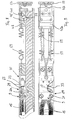
- the push rod 5 is in the embodiment shown from a push rod base element 5a and one relative to this by means of the integrated auxiliary power drive movable push rod actuator 5b, which in Exemplary embodiment shown telescopically by means of a Auxiliary drive for the axial extension of the push rod 5 can be extended.
- the push rod base element 5a On the push rod base element 5a is a rubber elastic Cable attached to cable attachment points 9 and from these attachment points (near the end of the Push rod base element 5a) over at the other end of the Push rod base element 5a seated deflection rollers 11 deflected and forming a loop 13 in the hollow Cross section of the push rod base element 5a (on the further design details of the push rod will be discussed later with reference to Figures 5ff).
- the rubber-elastic cable 15 is of the Loop reversal 13 moved back in parallel again, and namely a deflection roller parallel to the first deflection roller 11 11 to the second rope attachment point 9.
- the relatively movable push rod actuator 5b in normal operation more or less entirely in the push rod basic element 5a inserted, the loop 13 the rear end of the inserted push rod actuator 5b pressurized. In this basic position the system is excited, as shown in Figure 3 is.
- a corresponding locking mechanism is used in abnormal operation released so that by the tensile force of the rubber elastic Cable 15 over the at the rear end of Push rod actuator 5b attacking the loop Push rod actuator in the sense of an axial extension the entire push rod 5 relative to that on the belt drive 3 supported push rod base element 5a extends.
- the auxiliary drive thus formed in the abnormal case by the aforementioned axial extension of the push rod 5 overall, even with the belt drive 3 stationary, the respective one Sliding door leaf in its open position shown in Figure 2 be moved.
- the push rod 5 from a push rod basic element with a U-shaped cross section 5a which in the exemplary embodiment shown consists of two L-shaped in cross section and formed symmetrically to each other and correspondingly assembled shell parts 5 'and 5 "( Figures 10 to 15).
- Guide approaches 27 formed a free space by his Dimension is designed so that it is just the rubber elastic Cable 15 from the front pulleys 11 coming inside the push rod base element 5a to can be moved to the rear loop 13, wherein the rear loop 13 of the rubber-elastic cable 15 the rear end of the push rod actuator 5b always grips securely and thereby the push rod adjusting element 5b with the power of rubber elastic Cable 15 pressurized.
- bracing is not fixed to the base element 5a, but firmly on one opposite the push rod base element 5a at its rear end over a certain axial travel relatively adjustable and the clamping plate 33 comprehensive trigger slide 35, on its importance will be discussed later.
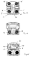
- the diameter of the locking roller 37 is larger than the thickness of the rear portion 43 of the push rod base 5a. On the opposite faces the locking roller 37 sit pin 45, about which Locking roller 37 sits non-slip ( Figure 15).
- the locking roller 37 When pushing in the push rod actuator 5b, the locking roller 37 then falls with a partial diameter range into one on the top of the push rod actuator 5b trained locking recess 51, the height of which is approximately the thickness of the slide plate 47a corresponds.
- the locking recess 51 is designed in the form of a cutout in the direction of thrust leading and trailing with a bevel, i.e. with a rising edge deviating from a step paragraph is.
- the holding magnet holds in this position shown in FIG. 19 55 the anchor plate 53 with the slide 47 in the locked position.
- the adjustment mechanism described also shows that the length of the locking recess 51 such is that a feed and take-along movement of the slide 47 from the position shown in Figures 16 and 17 (Unlocking position) up to that in FIGS. 18 and 19 locking position shown is enabled.
- FIGS. 6 to 9 includes the embodiment also a rope monitoring device 61. Not only if the rubber elastic breaks Cable 15, but also when the biasing force falls below a preset value, will automatically the sliding door even when the belt drive is not moving be moved into the open position.
- Tension springs 59 have a double function in this respect. On the one hand they are not only used to switch the slide falling holding magnet (i.e. in the event of a power failure), but they also serve for rope monitoring by they counteract the rubber force. Because the kind of further slide trained and on the push rod base element 5a only along a certain axial path displaceable and formed in the manner of a trigger slide Rope monitoring device 61 is not separate Tension springs, but over the already mentioned common Tension springs 59 supported, over which the slide 47 and the rope monitoring device formed in the manner of a slider 61 are held too biased towards each other.
Landscapes
- Business, Economics & Management (AREA)
- Emergency Management (AREA)
- Power-Operated Mechanisms For Wings (AREA)
- Wing Frames And Configurations (AREA)
Description
- Figur 1 :
- eine schematische auszugsweise Seitenansicht der erfindungsgemäßen automatischen Schiebetür mit zwei im geschlossenen Zustand gezeigten Flügeltüren;
- Figur 2 :
- eine zu Figur 1 entsprechende Darstellung bei geöffneten Flügeltüren;
- Figur 3 :
- eine perspektivische Schema-Darstellung des Hilfsantriebes unter Verwendung eines gummielastischen Seilzuges in gespanntem Zustand (im Normbetrieb);
- Figur 4 :
- eine entsprechende Darstellung zu Figur 3 bei entspanntem Seilzug (im Abnormbetrieb);
- Figur 5 :
- eine auszugsweise Seitenansicht der erfindungsgemäßen Schubstange;
- Figur 6 :
- eine auszugsweise Längs-Vertikalschnittdarstellung durch das rückwärtige Ende der erfindungsgemäßen Schubstange in gespannter Position;
- Figur 7 :
- eine entsprechende Draufsicht auf die Darstellung gemäß Figur 6;
- Figur 8 :
- eine zu Figur 6 entsprechende auszugsweise Vertikalschnittdarstellung in entriegelter aber noch gespannter Position;
- Figur 9 :
- eine entsprechende Draufsicht auf die Darstellung gemäß Figur 8;
- Figur 10 :
- eine axiale Draufsicht auf das vordere Ende der Seilumlenkung der Schubstange;
- Figur 11 :
- ein entsprechender Querschnitt durch die Gummiseilklemmvorrichtung der erfindungsgemäßen Schubstange;
- Figur 12 :
- ein entsprechender Querschnitt durch die erfindungsgemäße Schubstange in Höhe der Zugfeder;
- Figur 13 :
- eine entsprechende Querschnittsdarstellung durch die erfindungsgemäße Schubstange am vorderen Ende des Systems;
- Figur 14 :
- eine entsprechende Querschnittsdarstellung durch die erfindungsgemäße Schubstange vor dem Seilüberwachungsschalter;
- Figur 15 :
- ein Querschnitt durch die erfindungsgemäße Schubstange im Bereich der Verriegelungsrolle;
- Figuren 16 bis 19 :
- auszugsweiser Längs-/Vertikalschnitt durch die erfindungsgemäße Schubstange zur Erläuterung des Funktionsmechanismus in schiedenen Schaltstellungen.
Claims (16)
- Automatische Schiebetür mit mindestens einem Flügel (1), mit den folgenden Merkmalengekennzeichnet durch die folgenden weiteren, den Hilfsantrieb betreffende Merkmaleder zumindest eine Flügel (1) ist betrieblich mit einem verfahrbaren Antriebs-Übertragungsmittel (3) vorzugsweise in Form eines umlaufend verlegten Riemens gekoppelt,ein Hilfsantrieb ist vorhanden, der bei Ausfall der das Antriebs-Übertragungsmittel (3) verfahrenden Antriebseinrichtung mittels einer Auslöseeinrichtung derart ausgelöst wird, daß bei Stromausfall der Hilfsantrieb zum selbständigen Verfahren des ihm zugeordneten Türflügels (1) freigegeben wird,der Hilfsantrieb stützt sich zumindest mittelbar zum einen an dem ihm zugeordneten Türflügel (1) und zum anderen zumindest mittelbar an dem Antriebs-Übertragungsmittel (3) ab und ist im Normalbetrieb mit dem Antriebs-Übertragungsmittel (3) und dem ihm zugeordneten Türflügel (1) mit bewegbar,der zumindest eine Türflügel (1) ist mit dem Antriebs-übertragungsmittel (3) mittelbar unter Zwischenschaltung einer Schubstange (5) gekoppelt,die Schubstange (5) ist zumindest zweigeteilt und umfaßt ein Schubstangen-Grundelement (5a), welches mit dem Antriebs-Übertragungsmittel (3) gekoppelt und mit diesem mit verfahrbar ist, und ein Schubstangen-Stellelement (5b), welches gegenüber dem Schubstangen-Grundelement (5a) bei Wirksamwerden des Hilfsantriebes unter Verstellung des ihm zugeordneten Türflügels (1) in Öffnungsstellung selbst bei nicht betätigtem Antriebs-Übertragungsmittel (3) verfahrbar ist, undder Hilfsantrieb wirkt zumindest mittelbar zwischen dem Schubstangen-Grundelement (5a) und dem relativ dazu verfahrbaren Schubstangen-Stellelement (5b).
- Automatische Schiebetür nach Anspruch 1, dadurch gekennzeichnet, daß das Schubstangen-Stellelement (5b) gegenüber dem Schubstangen-Grundelement (5a) teleskopartig ausfahrbar oder mit Seitenversatz dazu längs verfahrbar geführt ist.
- Automatische Schiebetür nach Anspruch 1 oder 2, dadurch gekennzeichnet, daß das Schubstangen-Grundelement (5a) im wesentlichen ein Hohlprofil, vorzugsweise ein U- oder C-förmiges Profil aufweist, in welchem an Gleitflächen (29) abgestützt das Schubstangen-Stellelement (5b) axial vor- oder ausfahrbar gelagert ist.
- Automatische Schiebetür nach einem der Ansprüche 1 bis 3, dadurch gekennzeichnet, daß das verfahrbare Schubstangen-Stellelement (5b) unter Vorspannung des Hilfsantriebes am Schubstangen-Grundelement (5a) in gespanntem Zustand mittels einer mechanischen Verriegelungseinrichtung gesichert ist.
- Automatische Schiebetür nach Anspruch 4, dadurch gekennzeichnet, daß die mechanische Verriegelungseinrichtung zur Freigabe des Schubstangen-Stellelementes (5b) mittels einer magnetisch betätigbaren Freigabe- und Auslöseeinrichtung entriegelbar ist.
- Automatische Schiebetür nach einem der Ansprüche 1 bis 5 mit einem gummielastischen Seil (15) als Hilfsantrieb, dadurch gekennzeichnet, daß das gummielastische Seil (15) an seinem einen Ende am Schubstangen-Grundelement (5a) an einer Befestigungsstelle (9) verankert und versetzt dazu um eine Umlenkstelle (11) am Schubstangen-Grundelement (5a) umgelenkt und zurückgeführt ist und vorzugsweise am rückwärtigen Ende des ausfahrbaren Schubstangen-Stellelementes (5b) an einer weiteren Abstützstelle angreift.
- Automatische Schiebetür nach Anspruch 6, dadurch gekennzeichnet, daß das gummielastische Seil (15) doppelt verlegt ist und am rückwärtigen Ende des verfahrbaren Schubstangen-Stellelementes (5b) unter Bildung einer rückwärtig am Schubstangen-Stellelement (5b) unter Vorspannung anliegenden Seilschlaufe (13) herum und von dort um eine zur ersten Umlenkstelle (11) seitlich versetzt liegende Umlaufstelle (11) zu einer rückwärtigen Befestigungsstelle (9) am Schubstangen-Grundelement (5a) geführt ist.
- Automatische Schiebetür nach einem der Ansprüche 1 bis 7, dadurch gekennzeichnet, daß die Freigabe- und Auslöseeinrichtung nach Art eines Schiebers (47) gebildet ist, der auf dem Schubstangen-Grundelement (5a) lediglich in Axialrichtung wegbegrenzt verstellbar ist, und der nach Einschieben des Schubstangen-Stellelementes (5b) unter Kupplung und/oder Verriegelung der Freigabe- und Auslöseeinrichtung eine mechanische Sperre betätigt, worüber das verfahrbare Schubstangen-Stellelement (5b) unter Vorspannung des Hilfsantriebes am Schubstangen-Grundelement (5a) abgestützt gehalten ist.
- Automatische Schiebetür nach Anspruch 7 oder 8, dadurch gekennzeichnet, daß bei Stromausfall die Auslöse-/Freigabeeinrichtung automatisch in Freigabestellung umschaltbar ist, wodurch die mechanische Verriegelung des Schubstangen-Stellelementes (5b) aufhebbar ist.
- Automatische Schiebetür nach einem der Ansprüche 1 bis 9, dadurch gekennzeichnet, daß ferner eine Seilüberwachungseinrichtung (61) vorgesehen ist, die bei Unterschreitung einer vorgebbaren Seilzugkraft bis unter einen minimalen Grenzwert die Freigabe-/Auslöseeinrichtung zur Freigabe des Schubstangen-Stellelementes (5b) freischaltet.
- Automatische Schiebetür nach Anspruch 10, dadurch gekennzeichnet, daß die Seilüberwachungseinrichtung (61) nach Art eines Schiebers gebildet ist, der auf dem Schubstangen-Grundelement (5a) in Axialrichtung wegbegrenzt verschiebbar ist, und daß an dem so gebildeten Schieber einerseits das gummielastische Seil (15) und in Gegenrichtung dazu eine Zugfeder (59) angreift, wobei die Auslösung der Seilzugüberwachungseinrichtung (61) dann erfolgt, wenn die Zugkräfte der Zugfedern (59) größer sind als die gegensinnig gerichteten Kräfte des Seilzuges (15).
- Automatische Schiebetür nach Anspruch 10 oder 11, dadurch gekennzeichnet, daß die Seilzugüberwachungseinrichtung (61) einen Seilzugschalter (63) umfaßt, der bei Verstellung des Schiebers in Auslösestellung des Hilfsantriebes den Seilzugschalter (63) zur Unterbrechung der den Haftmagneten (55) mit Strom versorgenden Leitung umschaltet.
- Automatische Schiebetür nach einem der Ansprüche 1 bis 12, dadurch gekennzeichnet, daß der Hilfsantrieb und damit die zumindest zweigeteilte, teleskopartig ausfahrbare Schubstange (5) aus einer axial wirkende Druckfederkonstruktion, insbesondere einer Gasdruckfeder besteht.
- Automatische Schiebetür nach einem der Ansprüche 1 bis 13, dadurch gekennzeichnet, daß der Haftmagnet (55) für die Auslöse-/Freigabeeinrichtung auf dem Schubstangen-Grundelement (5a) sitzt oder darüber abgestützt ist.
- Automatische Schiebetür nach Anspruch 14, dadurch gekennzeichnet, daß die Auslöse-/Freigabeeinrichtung eine senkrecht zu deren Bewegungsrichtung sitzende Ankerplatte (53) aufweist, die mit dem Haftmagnet (55) in Wechselwirkung tritt.
- Automatische Schiebetür nach einem der Ansprüche 1 bis 15, dadurch gekennzeichnet, daß die Auslöse-/Freigabeeinrichtung, die Ankerplatte (53) und der Haftmagnet (55) auf der Schubstange (5), insbesondere auf dem Schubstangen-Grundelement (5a) sitzen.
Applications Claiming Priority (2)
| Application Number | Priority Date | Filing Date | Title |
|---|---|---|---|
| DE19549006 | 1995-12-28 | ||
| DE19549006A DE19549006C2 (de) | 1995-12-28 | 1995-12-28 | Automatische Schiebetür mit mindestens einem Flügel |
Publications (3)
| Publication Number | Publication Date |
|---|---|
| EP0781892A2 EP0781892A2 (de) | 1997-07-02 |
| EP0781892A3 EP0781892A3 (de) | 1997-12-10 |
| EP0781892B1 true EP0781892B1 (de) | 2000-03-29 |
Family
ID=7781571
Family Applications (1)
| Application Number | Title | Priority Date | Filing Date |
|---|---|---|---|
| EP96119999A Expired - Lifetime EP0781892B1 (de) | 1995-12-28 | 1996-12-12 | Automatische Schiebetür mit mindestens einem Flügel |
Country Status (3)
| Country | Link |
|---|---|
| EP (1) | EP0781892B1 (de) |
| AT (1) | ATE191251T1 (de) |
| DE (2) | DE19549006C2 (de) |
Families Citing this family (5)
| Publication number | Priority date | Publication date | Assignee | Title |
|---|---|---|---|---|
| DE19908191C1 (de) * | 1999-02-25 | 2000-07-06 | Agta Record Ag Fehraltorf | Automatische Flügel- oder Türanlage |
| DE19963778A1 (de) | 1999-12-30 | 2001-07-05 | Agta Record Ag Fehraltorf | Schiebeflügelantrieb |
| DE10141313B4 (de) * | 2001-08-28 | 2005-09-15 | Dorma Gmbh + Co. Kg | Öffnungssicherung für ein automatisches Schiebetürsystem |
| DE10259750B3 (de) * | 2002-12-19 | 2004-01-08 | Agta Record Ag | Antrieb für eine Schiebetüranlage oder dergleichen |
| ITAN20100149A1 (it) * | 2010-09-10 | 2012-03-11 | Tekno Space S R L | Gruppo porta di sicurezza. |
Family Cites Families (2)
| Publication number | Priority date | Publication date | Assignee | Title |
|---|---|---|---|---|
| FR2663673B1 (fr) * | 1990-06-20 | 1992-10-23 | Faiveley Transport | Porte coulissante et son mecanisme de commande. |
| DE4400940C1 (de) * | 1994-01-14 | 1995-04-20 | Tuerautomation Fehraltorf Ag F | Automatische Schiebetür mit mindestens einem Flügel |
-
1995
- 1995-12-28 DE DE19549006A patent/DE19549006C2/de not_active Expired - Fee Related
-
1996
- 1996-12-12 EP EP96119999A patent/EP0781892B1/de not_active Expired - Lifetime
- 1996-12-12 DE DE59604833T patent/DE59604833D1/de not_active Expired - Fee Related
- 1996-12-12 AT AT96119999T patent/ATE191251T1/de not_active IP Right Cessation
Also Published As
| Publication number | Publication date |
|---|---|
| ATE191251T1 (de) | 2000-04-15 |
| EP0781892A2 (de) | 1997-07-02 |
| DE19549006C2 (de) | 1997-10-02 |
| EP0781892A3 (de) | 1997-12-10 |
| DE59604833D1 (de) | 2000-05-04 |
| DE19549006A1 (de) | 1997-07-03 |
Similar Documents
| Publication | Publication Date | Title |
|---|---|---|
| EP0227586B1 (de) | Elektrische Schalteinrichtung mit einem Einschubrahmen und einem darin einsetzbaren Schaltgerät | |
| EP1500763B1 (de) | Ausziehsperreinrichtung für mindestens zwei wechselweise aus einem Möbelkorpus ausziehbare Schubladen | |
| DE2211707C3 (de) | Passives Sicherheitsgurtsystem | |
| EP1374733A1 (de) | Schubladenführung | |
| EP3715570B1 (de) | Schiebetüranlage | |
| DE19503624C1 (de) | Vorrichtung zur Beeinflussung eines Fahrantriebes eines Schaltgerätes | |
| EP0172351A1 (de) | Fanggerät | |
| WO2004040726A2 (de) | Vorrichtung zur fixierung eines leistungsschalters in einem einschubrahmen | |
| EP0781892B1 (de) | Automatische Schiebetür mit mindestens einem Flügel | |
| DE3309039A1 (de) | Ausfahrbare trittstufe fuer kraftfahrzeuge oder dergleichen | |
| EP2552282A1 (de) | AUSSTOßVORRICHTUNG | |
| DE2261385C3 (de) | Elektromagnetische Verriegelungsvorrichtung eines Schlosses | |
| DE10040593A1 (de) | Verriegelungseinrichtung für längsverstellbare Sitze, insbesondere Kraftfahrzeugsitze | |
| DE3412136A1 (de) | Tuerschloss | |
| EP0019076B1 (de) | Führungsanordnung zum linearen Verstellen mindestens eines an einem Träger angeordneten Gegenstandes, insbesondere zur Parallelverstellung von Möbeleinschüben | |
| DE19908191C1 (de) | Automatische Flügel- oder Türanlage | |
| DE19747329A1 (de) | Vorrichtung zum Aufwickeln von textilen Warenbahnen | |
| EP0846825B1 (de) | Verriegelungsvorrichtung für ein in einer Zarge bewegbares Tür- oder Torblatt | |
| DE4234899A1 (de) | Schiebetürbeschlag für eine Schiebetüranlage | |
| DE3838415C2 (de) | ||
| DE102019108273B4 (de) | Verriegelungseinrichtung für eine Schiebetüranlage und Schiebetüranlage | |
| DE102019108275B4 (de) | Linearmotor zum Bewegen eines Verriegelungsmittels, Verriegelungseinrichtung für eine Schiebetüranlage und eine solche Schiebetüranlage | |
| DE29610175U1 (de) | Einrichtung zur Prüferstangenbrucherkennung | |
| DE19641513C1 (de) | Abschließeinrichtung zur Sperrung der Betätigung eines Fahrantriebes eines Leistungsschalters | |
| DE8716402U1 (de) | Staubsauger mit einer einteiligen Drucktaste |
Legal Events
| Date | Code | Title | Description |
|---|---|---|---|
| PUAI | Public reference made under article 153(3) epc to a published international application that has entered the european phase |
Free format text: ORIGINAL CODE: 0009012 |
|
| AK | Designated contracting states |
Kind code of ref document: A2 Designated state(s): AT BE CH DE FR GB IT LI NL SE |
|
| PUAL | Search report despatched |
Free format text: ORIGINAL CODE: 0009013 |
|
| AK | Designated contracting states |
Kind code of ref document: A3 Designated state(s): AT BE CH DE FR GB IT LI NL SE |
|
| 17P | Request for examination filed |
Effective date: 19980205 |
|
| RAP1 | Party data changed (applicant data changed or rights of an application transferred) |
Owner name: AGTA RECORD AG |
|
| GRAG | Despatch of communication of intention to grant |
Free format text: ORIGINAL CODE: EPIDOS AGRA |
|
| 17Q | First examination report despatched |
Effective date: 19990802 |
|
| GRAG | Despatch of communication of intention to grant |
Free format text: ORIGINAL CODE: EPIDOS AGRA |
|
| GRAH | Despatch of communication of intention to grant a patent |
Free format text: ORIGINAL CODE: EPIDOS IGRA |
|
| GRAH | Despatch of communication of intention to grant a patent |
Free format text: ORIGINAL CODE: EPIDOS IGRA |
|
| GRAA | (expected) grant |
Free format text: ORIGINAL CODE: 0009210 |
|
| AK | Designated contracting states |
Kind code of ref document: B1 Designated state(s): AT BE CH DE FR GB IT LI NL SE |
|
| PG25 | Lapsed in a contracting state [announced via postgrant information from national office to epo] |
Ref country code: SE Free format text: THE PATENT HAS BEEN ANNULLED BY A DECISION OF A NATIONAL AUTHORITY Effective date: 20000329 Ref country code: NL Free format text: LAPSE BECAUSE OF FAILURE TO SUBMIT A TRANSLATION OF THE DESCRIPTION OR TO PAY THE FEE WITHIN THE PRESCRIBED TIME-LIMIT Effective date: 20000329 Ref country code: IT Free format text: LAPSE BECAUSE OF FAILURE TO SUBMIT A TRANSLATION OF THE DESCRIPTION OR TO PAY THE FEE WITHIN THE PRE;WARNING: LAPSES OF ITALIAN PATENTS WITH EFFECTIVE DATE BEFORE 2007 MAY HAVE OCCURRED AT ANY TIME BEFORE 2007. THE CORRECT EFFECTIVE DATE MAY BE DIFFERENT FROM THE ONE RECORDED.SCRIBED TIME-LIMIT Effective date: 20000329 Ref country code: GB Free format text: LAPSE BECAUSE OF FAILURE TO SUBMIT A TRANSLATION OF THE DESCRIPTION OR TO PAY THE FEE WITHIN THE PRESCRIBED TIME-LIMIT Effective date: 20000329 Ref country code: FR Free format text: LAPSE BECAUSE OF FAILURE TO SUBMIT A TRANSLATION OF THE DESCRIPTION OR TO PAY THE FEE WITHIN THE PRESCRIBED TIME-LIMIT Effective date: 20000329 |
|
| REF | Corresponds to: |
Ref document number: 191251 Country of ref document: AT Date of ref document: 20000415 Kind code of ref document: T |
|
| REG | Reference to a national code |
Ref country code: CH Ref legal event code: EP |
|
| REF | Corresponds to: |
Ref document number: 59604833 Country of ref document: DE Date of ref document: 20000504 |
|
| REG | Reference to a national code |
Ref country code: CH Ref legal event code: NV Representative=s name: SCHMAUDER & PARTNER AG PATENTANWALTSBUERO |
|
| EN | Fr: translation not filed | ||
| NLV1 | Nl: lapsed or annulled due to failure to fulfill the requirements of art. 29p and 29m of the patents act | ||
| GBV | Gb: ep patent (uk) treated as always having been void in accordance with gb section 77(7)/1977 [no translation filed] |
Effective date: 20000329 |
|
| PGFP | Annual fee paid to national office [announced via postgrant information from national office to epo] |
Ref country code: DE Payment date: 20001109 Year of fee payment: 5 |
|
| PG25 | Lapsed in a contracting state [announced via postgrant information from national office to epo] |
Ref country code: AT Free format text: LAPSE BECAUSE OF NON-PAYMENT OF DUE FEES Effective date: 20001212 |
|
| PGFP | Annual fee paid to national office [announced via postgrant information from national office to epo] |
Ref country code: CH Payment date: 20001221 Year of fee payment: 5 |
|
| PG25 | Lapsed in a contracting state [announced via postgrant information from national office to epo] |
Ref country code: BE Free format text: LAPSE BECAUSE OF NON-PAYMENT OF DUE FEES Effective date: 20001231 |
|
| PLBE | No opposition filed within time limit |
Free format text: ORIGINAL CODE: 0009261 |
|
| STAA | Information on the status of an ep patent application or granted ep patent |
Free format text: STATUS: NO OPPOSITION FILED WITHIN TIME LIMIT |
|
| 26N | No opposition filed | ||
| BERE | Be: lapsed |
Owner name: AGTA RECORD A.G. Effective date: 20001231 |
|
| PG25 | Lapsed in a contracting state [announced via postgrant information from national office to epo] |
Ref country code: LI Free format text: LAPSE BECAUSE OF NON-PAYMENT OF DUE FEES Effective date: 20011231 Ref country code: CH Free format text: LAPSE BECAUSE OF NON-PAYMENT OF DUE FEES Effective date: 20011231 |
|
| PG25 | Lapsed in a contracting state [announced via postgrant information from national office to epo] |
Ref country code: DE Free format text: LAPSE BECAUSE OF NON-PAYMENT OF DUE FEES Effective date: 20020702 |
|
| REG | Reference to a national code |
Ref country code: CH Ref legal event code: PL |