EP0781894A2 - Méthode et appareil pour le service courant des puits - Google Patents
Méthode et appareil pour le service courant des puits Download PDFInfo
- Publication number
- EP0781894A2 EP0781894A2 EP96309438A EP96309438A EP0781894A2 EP 0781894 A2 EP0781894 A2 EP 0781894A2 EP 96309438 A EP96309438 A EP 96309438A EP 96309438 A EP96309438 A EP 96309438A EP 0781894 A2 EP0781894 A2 EP 0781894A2
- Authority
- EP
- European Patent Office
- Prior art keywords
- fluid
- housing
- packer
- plug
- well
- Prior art date
- Legal status (The legal status is an assumption and is not a legal conclusion. Google has not performed a legal analysis and makes no representation as to the accuracy of the status listed.)
- Withdrawn
Links
- 238000000034 method Methods 0.000 title claims abstract description 18
- 239000012530 fluid Substances 0.000 claims abstract description 125
- 238000004891 communication Methods 0.000 claims description 18
- 238000007789 sealing Methods 0.000 claims description 12
- 238000005086 pumping Methods 0.000 claims description 8
- 230000000977 initiatory effect Effects 0.000 claims description 5
- 230000015572 biosynthetic process Effects 0.000 abstract description 46
- IJGRMHOSHXDMSA-UHFFFAOYSA-N Atomic nitrogen Chemical compound N#N IJGRMHOSHXDMSA-UHFFFAOYSA-N 0.000 abstract description 22
- 229910052757 nitrogen Inorganic materials 0.000 abstract description 11
- 238000012360 testing method Methods 0.000 description 22
- 239000007789 gas Substances 0.000 description 9
- 230000006835 compression Effects 0.000 description 6
- 238000007906 compression Methods 0.000 description 6
- 238000005070 sampling Methods 0.000 description 5
- 238000004519 manufacturing process Methods 0.000 description 4
- 238000013459 approach Methods 0.000 description 3
- 230000000740 bleeding effect Effects 0.000 description 3
- 238000009530 blood pressure measurement Methods 0.000 description 3
- 230000002706 hydrostatic effect Effects 0.000 description 3
- 238000010998 test method Methods 0.000 description 3
- 238000009529 body temperature measurement Methods 0.000 description 2
- 238000005553 drilling Methods 0.000 description 2
- 230000035699 permeability Effects 0.000 description 2
- 239000007787 solid Substances 0.000 description 2
- 239000004568 cement Substances 0.000 description 1
- 230000008859 change Effects 0.000 description 1
- 238000010276 construction Methods 0.000 description 1
- 230000007423 decrease Effects 0.000 description 1
- 231100001261 hazardous Toxicity 0.000 description 1
- 230000007774 longterm Effects 0.000 description 1
- 239000000463 material Substances 0.000 description 1
- 230000008569 process Effects 0.000 description 1
- 238000012956 testing procedure Methods 0.000 description 1
- 238000012546 transfer Methods 0.000 description 1
Images

Classifications
-
- E—FIXED CONSTRUCTIONS
- E21—EARTH OR ROCK DRILLING; MINING
- E21B—EARTH OR ROCK DRILLING; OBTAINING OIL, GAS, WATER, SOLUBLE OR MELTABLE MATERIALS OR A SLURRY OF MINERALS FROM WELLS
- E21B49/00—Testing the nature of borehole walls; Formation testing; Methods or apparatus for obtaining samples of soil or well fluids, specially adapted to earth drilling or wells
- E21B49/08—Obtaining fluid samples or testing fluids, in boreholes or wells
- E21B49/081—Obtaining fluid samples or testing fluids, in boreholes or wells with down-hole means for trapping a fluid sample
-
- E—FIXED CONSTRUCTIONS
- E21—EARTH OR ROCK DRILLING; MINING
- E21B—EARTH OR ROCK DRILLING; OBTAINING OIL, GAS, WATER, SOLUBLE OR MELTABLE MATERIALS OR A SLURRY OF MINERALS FROM WELLS
- E21B43/00—Methods or apparatus for obtaining oil, gas, water, soluble or meltable materials or a slurry of minerals from wells
-
- E—FIXED CONSTRUCTIONS
- E21—EARTH OR ROCK DRILLING; MINING
- E21B—EARTH OR ROCK DRILLING; OBTAINING OIL, GAS, WATER, SOLUBLE OR MELTABLE MATERIALS OR A SLURRY OF MINERALS FROM WELLS
- E21B43/00—Methods or apparatus for obtaining oil, gas, water, soluble or meltable materials or a slurry of minerals from wells
- E21B43/12—Methods or apparatus for controlling the flow of the obtained fluid to or in wells
Definitions
- This invention relates to a method and apparatus for servicing a well wherein a fluid sample is obtained without lowering the pressure of the fluid below the bubble pressure thereof, a condition known as "flashing.”
- One very commonly used well testing procedure is to first cement a casing into the borehole and then to perforate the casing adjacent zones of interest. Subsequently, the well is flow tested through the perforations. Such flow tests are commonly performed with a drill stem test string which is a string of tubing located within the casing.
- the drill stem test string carries packers, tester valves, circulating valves and the like to control the flow of fluids through the drill stem test string.
- drill stem testing of cased wells provides very good test data, it has the disadvantage that the well must first be cased before the test can be conducted. Also, better reservoir data can be obtained immediately after the well is drilled and before the formation has been severely damaged by drilling fluids and the like.
- pad-type wireline testers which simply press a small resilient pad against the sidewall of the borehole and pick up very small unidirectional samples through an orifice in the pad.
- An example of such a pad-type tester is shown in U. S. Patent No. 3,577,781 to Lebourg.
- the primary disadvantage of pad-type testers is they take a very small unidirectional sample which is often not truly representative of the formation because it is "dirty" fluid which provides very little data on the production characteristics of the formation. It is also sometimes difficult to seal the pad. When the pad does seal, it is subject to differential sticking and sometimes the tool may be damaged when it is removed.
- the methods and apparatus of the present invention reduce or overcome these problems by providing for capturing or trapping of a sample after fluid has flowed for a period of time. This prevents the capturing of the "dirty" fluid which initially comes out of the formation or zone of interest, while allowing the capturing of a sample of the cleaner, more representative fluid behind the "dirty” fluid.
- a possible disadvantage of such a surge chamber device would be that it causes the fluid to flow quite quickly which may result in flashing of the fluid, and if this fluid flows into a sampler, the flashed fluid may not be representative of the actual formation fluid and may result in incorrect readings on pressure and temperature instrumentation.
- the present invention solves this problem by providing a controlled, relatively slow flowing of fluid from the formation which prevents flashing and allows a good sample to be obtained in a sampler.
- a system including an outer tubing string having an inflatable packer, and a communication passage disposed through the tubing string below the packer, an inflation passage communicated with the inflatable element of the packer, and an inflation valve controlling flow of inflation fluid through the inflation passage.
- the inflation valve is constructed so that the opening and closing of the inflation valve is controlled by a surface manipulation of the outer tubing string.
- an inner well tool such as a surge chamber
- an inner well tool such as a surge chamber
- the outer tubing string may be run into and engaged with the outer tubing string to place the inner well tool in communication with a subsurface formation through the communication passage.
- a straddle packer having upper and lower packer elements which are engaged on opposite sides of the formation.
- the well fluid samples are collected by running an inner tubing string, preferably an inner coiled tubing string, into the previously described outer tubing string.
- the coiled tubing string is engaged with the outer tubing string, and the bore of the coiled tubing string is communicated with a subsurface formation through the circulation passage defined in the outer tubing string. Then well fluid from the subsurface is flowed through the communication passage and up the coiled tubing string.
- Such a coiled tubing string may include various valves for control of fluid flow therethrough.
- This prior invention does not include the use of a sampler downhole to obtain the fluid sample.
- the sample is taken in a sampler near the zone of interest so that it is not necessary to flow fluid to the surface, and the sample is trapped at or near the same conditions as the fluid in the zone itself.
- the flashing problem is eliminated by controlling the flow of fluid from the formation and the resulting pressure drop so that the pressure of the fluid does not drop below the bubble pressure when the sample is taken.
- One aim of the method and apparatus of the present invention is to obtain a fluid sample of clean, representative fluid from a well formation or zone of interest. This is accomplished by flowing fluid from the formation through the tool without flashing of the fluid, flowing sufficient fluid so that "dirty" fluid initially flowed out of the formation or zone of interest is captured in the sampler, and then capturing the clean fluid in the sampler.
- a method of servicing a well which method comprises the steps of:
- the invention also includes apparatus for use in servicing a well and obtaining a fluid sample from a subsurface zone of interest, said apparatus comprising: a housing connectable to a tubing string; a packer connected to said housing and adapted for sealingly engaging an inner surface of said well; a sampler in communication with said housing; and means for flowing fluid through said packer into said housing in a controlled manner such that a fluid sample may be captured in said sampler without lowering the pressure of any fluid in said housing or sampler below the bubble point thereof.
- An apparatus of the invention for use in servicing a well and obtaining a fluid sample from a subsurface zone or formation comprises a housing connectable to a tubing string, a packer connected to the housing and adapted for sealingly engaging an inner surface of the well adjacent to the zone of interest, a sampler in communication with the housing, a means for flowing fluid through the packer into the housing in a controlled manner such that a fluid sample may be captured in the sampler without lowering the pressure of any fluid in the housing or sampler below the bubble point thereof. That is, the means for flowing fluid through the packer is adapted for doing so in a controlled manner such that the fluid does not flash.
- the means for flowing is characterized by a pump positionable in the housing and adapted for pumping fluid therefrom.
- a pair of plugs may be disposed in the housing.
- a first or upper plug is disposed above a second or lower plug.
- the lower plug preferably has a time delay valve disposed therein.
- This time delay valve has an initially open position and is actuatable to a closed position after a predetermined time delay.
- the upper plug is flowed upwardly through the housing and substantially dirty fluid is moved between the upper and lower plugs.
- the valve moves to its closed position such that the lower plug is flowed upwardly through the housing and substantially clean fluid is moved below the lower plug.
- a sealing means is provided for sealing between the upper and lower plugs and an inner surface of the housing.
- the packer element of the packer is inflatable to a sealing position engaging the inner surface of the well. This inflation may be carried out by using fluid displaced by pumping the plugs downwardly through the housing.
- the pump is preferably an electric pump positioned in the housing at the end of an electric wireline.
- the means for flowing is characterized by a gas cushion in at least a portion of the tubing string.
- the gas cushion may be bled to lower the pressure thereof and thereby cause fluid flow from the zone of interest.
- this gas cushion is a nitrogen cushion. The gas cushion is bled relatively slowly so that the fluid does not flash.
- a method of the invention comprises the steps of running the apparatus into the well, setting the packer such that the packer element is sealingly engaged with the inner surface of the well adjacent to the zone of interest, initiating fluid flow from the zone, controlling the fluid flow and corresponding pressure drop such that flashing of the fluid within the housing is prevented, and capturing a sample of the fluid in the sampler.
- the step of controlling the fluid preferably comprises flowing dirty fluid from the zone for a sufficient time so that clean fluid is flowing into the housing prior to the step of capturing a sample.
- the step of initiating flow may comprise actuating a pump having an inlet in communication with the housing, and the step of controlling the fluid flow is characterized by controlling the pumping rate of fluid through the pump.
- the step of controlling the fluid flow comprises flowing fluid through the time delay valve in the second plug when the time delay valve is in its open position and thereby flowing the first plug upwardly through the housing, and closing the time delay valve and thereby flowing the second plug upwardly through the housing.
- the step of setting the packer may comprise pumping the first and second plugs downwardly through the housing so that fluid therebelow is displaced into the packer for inflation thereof.
- the steps of initiating fluid flow and controlling the fluid flow may comprise relatively slowly bleeding a gas cushion in the apparatus.
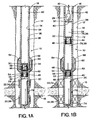
- FIGS. 1A-1C show a first embodiment of the apparatus for use in the method of testing a well of the present invention, using a pump and plugs to control flow of formation fluid.
- FIG. 2 illustrates a second embodiment of the present invention which utilizes a nitrogen cushion for controlling fluid formation flow.
- FIGS. 1A-1C A first embodiment of the apparatus for testing a well of the present invention is shown and generally designated by the numeral 10.
- Apparatus 10 is shown as it is run into a well 12.
- Apparatus 10 is particularly well adapted for use in a well 12 having an uncased borehole 14, but the invention is not intended to be so limited
- borehole 14 intersects a subsurface formation or zone of interest 16.
- zone of interest includes a subsurface formation.
- Apparatus 10 is at the lower end of a tubing string 18.
- apparatus 10 includes a Halliburton Hydrospring tester assembly 20 which includes an inflatable packer 22 having upper and lower inflatable packer elements 24 and 26, respectively.
- Packer elements 24 and 26 are adapted to sealingly engage borehole 14 on opposite sides of formation 16 or at desired, spaced locations in a zone of interest 16.
- a single element inflatable packer may be used above the formation or in the zone of interest instead of straddle packer 22. That is, the apparatus is not intended to be limited specifically to a straddle packer configuration. Testing with either type of packer is essentially the same.
- Hydrospring tester 20 is shown with an inflatable packer 22, the apparatus could also be configured with a compression packer as well.
- a compression packer could be easily used when the tool is on the bottom of well 12, and an inflatable packer could be used above the bottom.
- apparatus 10 is lowered into wellbore 14 as shown in FIG. 1A. Subsequently, a pump 28 is lowered down tubing string 18 and into the upper portion of apparatus 10 as seen in FIG. 1B. Pump 28 is preferably an electric pump which is lowered on a wireline 30. FIG. 1B illustrates an operating position of pump 28 spaced at a distance above Hydrospring tester 20.
- a sealing means 32 sealingly engages pump 28 with an inner bore 34 of a tubular portion or housing 36 of apparatus 10.
- a chamber 38 is defined in apparatus 10 between pump 28 and Hydroflate tester 20.
- An inlet 40 of pump 28 opens into chamber 38, and the pump discharges into central opening 42 of tubing string 18.
- first or upper plug 44 and a second or lower plug 46 are positioned in chamber 38.
- First and second plugs 44 and 46 are shown in a downwardmost position with second plug 46 adjacent to the top of Hydrospring tester 20 and first plug 44 adjacent to the top of second plug 46.
- apparatus 10 is assembled with first and second plugs 44 and 46 in the position shown in FIG. 1A.
- first and second plugs 44 and 46 may be dropped at the surface and pumped downwardly through tubing string 18 into apparatus 10 to the position shown. As will be further described herein, this procedure might be used as part of inflation of packer 22.
- First plug 44 is of a kind generally known in the art comprising a substantially solid body 48 with an outer sealing member having a plurality of wiper rings 50 extending therefrom and sealingly engaged with inner bore 34. No fluid can flow by first plug 44.
- Second plug 46 comprises a body 52 with an outer sealing member having a plurality of wiper rings 54 extending therefrom and sealingly engaged with inner bore 34. No fluid can flow around the outside of second plug 46. Disposed in body 52 is a time delay valve 56. Time delay valve 56 is normally open so that a flow passage 58 is defined longitudinally through second plug 46. Thus, in the position shown in FIG. 1A, first plug 44 is in fluid communication with Hydrospring tester 20 by means of flow passage 58.
- a sampler 60 such as a Halliburton Mini-sampler, is connected to housing 36 by a connector 62 or any other means known in the art.
- connector 62 is in communication with chamber 38.
- An electronic pressure and/or temperature recording instrument 64 also referred to as a recorder 64, is connected to tubular portion 36 by a connector 66 or any other means known in the art. Recorder 66 may be similar to the Halliburton HMR. An electronic memory recording fluid resistivity tool, such as manufactured by Sonex or Madden, might be substituted for recorder 66 or used therewith.
- An outer cover 68 may be positioned around housing 36, and connected thereto or forming a portion thereof, as desired to protect sampler 60 and recorder 64.
- apparatus 10 is run into well 12 to the desired depth on the end of tubing string 18 as generally seen in FIG. 1A.
- first and second plugs 44 and 46 are disposed in housing 36 adjacent to Hydrospring tester 20 as shown.
- Packer 22 is set in a manner known in the art so that upper and lower packer elements 24 and 26 of the packer are placed in sealing engagement with borehole 14 adjacent to formation or zone 16, as seen in FIG. 1B.
- a sampling port 70 between upper and lower packer elements 24 and 26 is in communication with zone 16 and isolated from well annulus portion 72 above upper packer element 24 and well annulus portion 74 below lower packer element 26.
- apparatus 10 may be positioned in borehole 14 without first and second plugs 44 and 46 being disposed in the apparatus.
- packer 22 is an inflatable packer which is inflated by pumping first and second plugs 44 and 46 down tubing string 18.
- first and second plugs 44 and 46 enter housing 36 to force necessary fluid therein into packer elements 24 and 26 to inflate them.
- a relief or control valve (not shown) in packer 22 prevents overinflation of the packer elements.
- Hydrospring tester 20 is operated in a manner known in the art to place flow passage 58 and second plug 46 in - communication with sampling port 70.
- Pump 28 is energized to draw the fluid out of chamber 38.
- This causes formation fluid from zone or formation 16 to flow through Hydrospring tester 20 and flow passage 58 in second plug 46 so that first plug 44 is moved upwardly through tubular portion 36. See FIG. 1B.
- wiper rings 50 provide sealing engagement between the first plug and inner bore 34 of housing 36 so that the fluid in an upper chamber portion 76 of chamber 38 above first plug 44 is isolated from the initial formation fluid flowing into a lower chamber portion 78 formed between first plug 44 and second plug 46.
- This initial fluid flowing from zone or formation 16 is frequently "dirty" and not representative of the actual fluid in the formation or zone. That is, the "dirty” fluid may have debris or other materials as a result of the drilling process contained therein, and the formation fluid flowing from deeper in the formation or zone, after this initial "dirty” fluid, is much more representative.
- Time delay valve 56 in second plug 46 is adapted to close, as shown in FIG. 1C, after a predetermined time delay. This time delay is selected so that valve 56 closes flow passage 58 after the "dirty" fluid has flowed and only clean fluid is flowing therethrough.
- sampler 60 is activated, and a sample of fluid is taken from chamber portion 79 and captured in the sampler. Actual operation of sampler 60 is in a manner known in the art.
- Recorder 64 may also be activated to take the appropriate pressure/temperature measurements as desired and send them to the surface.
- the actual operation of recorder 64 is also in a manner known in the art.
- apparatus 10 After completion of the test, apparatus 10 is retrieved to the surface. There, sampler 60 is removed. Sampler 60 may be drained on location, its contents may be transferred to a sample bottle for shipment to a pressure-volume-test (PVT) laboratory, or the entire sampler 60 may be shipped to a PVT laboratory for fluid transfer and testing.
- PVT pressure-volume-test
- Memory gauges and recorders 64 may be read, and the pressure, temperature and resistivity data analyzed to determine formation or zone pressure and temperature, permeability, and sample fluid resistivity.
- FIG. 2 a second embodiment of the apparatus for testing a well of the present invention is shown and generally designated by the numeral 80.
- Apparatus 80 is shown as it is in an operating position in well 12.
- second embodiment apparatus 80 is particularly well adapted for use in a well 12 having an uncased borehole 14, but the invention is not intended to be so limited.
- borehole 14 intersects a subsurface formation or zone of interest 16.
- Apparatus 80 is at the lower end of, or forms a lower portion of, a tubing string 82.
- apparatus 80 includes a Halliburton Hydrospring tester assembly 84 which includes an inflatable packer 86 having upper and lower inflatable packer elements 88 and 90, respectively.
- packer elements 88 and 90 are sealingly engaged with borehole 14 on opposite sides of formation 16 or if desired, spaced locations in a zone of interest 16.
- a single element inflatable packer may be used above the formation or in the zone of interest instead of straddle packer 86. That is, the apparatus is not intended to be limited specifically to a straddle packer configuration. Testing with either type of packer is essentially the same.
- Hydrospring tester 84 is shown with an inflatable packer 86
- apparatus 80 could also be configured with a compression packer as well.
- a compression packer could easily be used when apparatus 80 is on the bottom of well 12; and an inflatable packer could be used above the bottom.
- Tubing string 82 defines a central opening 92 therethrough, and at least a portion of central opening 92 is filled with a gas such as nitrogen.
- central opening 92 may also be referred to as a nitrogen or gas cushion 92.
- a sampler 90 such as a Halliburton Mini-sampler, is connected to tubing string 82 by a connector 96 or any other means known in the art.
- connector 96 is in communication with nitrogen cushion 92.
- An electronic pressure and/or temperature recording instrument 98 also referred to as a recorder 98, is connected to tubing string 82 by a connector 100 or any other means known in the art. Recorder 98 may be similar to the Halliburton HMR. An electronic memory recording fluid resistivity tool, such as manufactured by Sonex or Madden, might be substituted for recorder 98 or used therewith. An outer cover 102 may be positioned around tubing string 82, and connected thereto or forming a portion thereof, as desired to protect sampler 94 and recorder 98.
- Apparatus 80 is run into well 12 to the desired depth on the end of tubing string 82 and packer 86 is set so that a sampling port 104 between upper and lower packer elements 88 and 90 is in communication with formation or zone 16 and sealingly separated from upper well annulus portion 106 above upper packer element 88 and lower well annulus portion 108 below lower packer element 90.
- a control head 110 at the surface is operated to bleed the nitrogen from the nitrogen cushion 92.
- Hydrospring tester 20 is operated in a manner known in the art to place the lower end of central opening 92 in communication with sampling port 104.
- the bleeding of nitrogen from nitrogen cushion 92 causes the pressure to drop and this in turn causes formation fluid from zone or formation 16 to flow through Hydrospring tester 84 and into the lower end of central opening 92.
- "dirty" fluid will flow into central opening 92, and after a period of time, clean fluid will enter.
- sampler 94 and recorder 98 may be activated in the manner previously described for the first embodiment.
- Apparatus 80 may then be retrieved to the surface and the sample handled in the same manner as previously described.
- control of fluid from chamber 38 or 92 allows clean fluid flow to sampler 60 or 94 in a controlled manner.
- the pressure drop resulting from the actuation of pump 28 or the bleeding of nitrogen cushion 92 in first embodiment 10 and second embodiment 80, respectively, is such that the fluid flowing does not flash. That is, the pressure drop is controlled so that the pressure is not allowed to drop below the bubble point of the oil contained in the fluid.
- a phase change will occur as gas breaks out of solution. This is an undesirable situation which can result in non-representative samples and incorrect pressure and temperature measurements and can even result in a hazardous condition.
- control of the flow and corresponding pressure drop is maintained to prevent this flashing.
Landscapes
- Life Sciences & Earth Sciences (AREA)
- Engineering & Computer Science (AREA)
- Geology (AREA)
- Mining & Mineral Resources (AREA)
- Physics & Mathematics (AREA)
- Environmental & Geological Engineering (AREA)
- Fluid Mechanics (AREA)
- General Life Sciences & Earth Sciences (AREA)
- Geochemistry & Mineralogy (AREA)
- Sampling And Sample Adjustment (AREA)
Applications Claiming Priority (2)
| Application Number | Priority Date | Filing Date | Title |
|---|---|---|---|
| US578842 | 1995-12-26 | ||
| US08/578,842 US5687791A (en) | 1995-12-26 | 1995-12-26 | Method of well-testing by obtaining a non-flashing fluid sample |
Publications (2)
| Publication Number | Publication Date |
|---|---|
| EP0781894A2 true EP0781894A2 (fr) | 1997-07-02 |
| EP0781894A3 EP0781894A3 (fr) | 1999-01-20 |
Family
ID=24314547
Family Applications (1)
| Application Number | Title | Priority Date | Filing Date |
|---|---|---|---|
| EP96309438A Withdrawn EP0781894A3 (fr) | 1995-12-26 | 1996-12-23 | Méthode et appareil pour le service courant des puits |
Country Status (4)
| Country | Link |
|---|---|
| US (1) | US5687791A (fr) |
| EP (1) | EP0781894A3 (fr) |
| CA (1) | CA2193270A1 (fr) |
| NO (1) | NO965447L (fr) |
Cited By (3)
| Publication number | Priority date | Publication date | Assignee | Title |
|---|---|---|---|---|
| EP0896126A3 (fr) * | 1997-08-04 | 2000-04-05 | Halliburton Energy Services, Inc. | Dispositif et procédé d'essai de puits |
| WO2001027432A3 (fr) * | 1999-10-09 | 2001-10-04 | Schlumberger Ltd | Procedes et appareil pour realiser des mesures sur des fluides produits par des formations souterraines |
| DE102004041334B3 (de) * | 2004-08-20 | 2006-03-23 | Gfi Grundwasserforschungsinstitut Gmbh Dresden | Vorrichtung zur verfälschungsfreien teufenbezogenen isobaren Entnahme von Grundwasserproben |
Families Citing this family (45)
| Publication number | Priority date | Publication date | Assignee | Title |
|---|---|---|---|---|
| US6065355A (en) * | 1997-09-23 | 2000-05-23 | Halliburton Energy Services, Inc. | Non-flashing downhole fluid sampler and method |
| US6006834A (en) * | 1997-10-22 | 1999-12-28 | Halliburton Energy Services, Inc. | Formation evaluation testing apparatus and associated methods |
| EP0999348A3 (fr) | 1998-11-02 | 2000-11-29 | Halliburton Energy Services, Inc. | Chambre d'échantillonnage de liquides avec revêtement non-réactif |
| US6325146B1 (en) * | 1999-03-31 | 2001-12-04 | Halliburton Energy Services, Inc. | Methods of downhole testing subterranean formations and associated apparatus therefor |
| US6216782B1 (en) * | 1999-05-18 | 2001-04-17 | Halliburton Energy Services, Inc. | Apparatus and method for verification of monophasic samples |
| EP1228290A4 (fr) * | 1999-11-05 | 2005-03-23 | Halliburton Energy Serv Inc | Verificateur de couches de forage, appareil et procede de test et de verification de l'etat du verificateur |
| US7096976B2 (en) * | 1999-11-05 | 2006-08-29 | Halliburton Energy Services, Inc. | Drilling formation tester, apparatus and methods of testing and monitoring status of tester |
| US7246664B2 (en) * | 2001-09-19 | 2007-07-24 | Baker Hughes Incorporated | Dual piston, single phase sampling mechanism and procedure |
| CA2476532A1 (fr) * | 2003-08-04 | 2005-02-04 | Pathfinder Energy Services, Inc. | Dispositif permettant d'obtenir des echantillons de fluide de formation de haute qualite |
| US7083009B2 (en) * | 2003-08-04 | 2006-08-01 | Pathfinder Energy Services, Inc. | Pressure controlled fluid sampling apparatus and method |
| US7596995B2 (en) | 2005-11-07 | 2009-10-06 | Halliburton Energy Services, Inc. | Single phase fluid sampling apparatus and method for use of same |
| US7874206B2 (en) * | 2005-11-07 | 2011-01-25 | Halliburton Energy Services, Inc. | Single phase fluid sampling apparatus and method for use of same |
| US7472589B2 (en) * | 2005-11-07 | 2009-01-06 | Halliburton Energy Services, Inc. | Single phase fluid sampling apparatus and method for use of same |
| US8429961B2 (en) * | 2005-11-07 | 2013-04-30 | Halliburton Energy Services, Inc. | Wireline conveyed single phase fluid sampling apparatus and method for use of same |
| US7631696B2 (en) * | 2006-01-11 | 2009-12-15 | Besst, Inc. | Zone isolation assembly array for isolating a plurality of fluid zones in a subsurface well |
| US7665534B2 (en) * | 2006-01-11 | 2010-02-23 | Besst, Inc. | Zone isolation assembly for isolating and testing fluid samples from a subsurface well |
| US7556097B2 (en) * | 2006-01-11 | 2009-07-07 | Besst, Inc. | Docking receiver of a zone isolation assembly for a subsurface well |
| US8636478B2 (en) * | 2006-01-11 | 2014-01-28 | Besst, Inc. | Sensor assembly for determining fluid properties in a subsurface well |
| US20070236215A1 (en) * | 2006-02-01 | 2007-10-11 | Schlumberger Technology Corporation | System and Method for Obtaining Well Fluid Samples |
| US8151879B2 (en) * | 2006-02-03 | 2012-04-10 | Besst, Inc. | Zone isolation assembly and method for isolating a fluid zone in an existing subsurface well |
| US20070199691A1 (en) * | 2006-02-03 | 2007-08-30 | Besst, Inc. | Zone isolation assembly for isolating a fluid zone in a subsurface well |
| JP5142769B2 (ja) * | 2008-03-11 | 2013-02-13 | 株式会社日立製作所 | 音声データ検索システム及び音声データの検索方法 |
| US7836951B2 (en) * | 2008-04-09 | 2010-11-23 | Baker Hughes Incorporated | Methods and apparatus for collecting a downhole sample |
| US7841402B2 (en) * | 2008-04-09 | 2010-11-30 | Baker Hughes Incorporated | Methods and apparatus for collecting a downhole sample |
| US8490694B2 (en) * | 2008-09-19 | 2013-07-23 | Schlumberger Technology Corporation | Single packer system for fluid management in a wellbore |
| US7967067B2 (en) * | 2008-11-13 | 2011-06-28 | Halliburton Energy Services, Inc. | Coiled tubing deployed single phase fluid sampling apparatus |
| US8839871B2 (en) * | 2010-01-15 | 2014-09-23 | Halliburton Energy Services, Inc. | Well tools operable via thermal expansion resulting from reactive materials |
| CA2810423C (fr) | 2010-09-22 | 2019-10-08 | Packers Plus Energy Services Inc. | Fermeture d'orifice tubulaire de puits de forage a ouverture retardee |
| US8474533B2 (en) | 2010-12-07 | 2013-07-02 | Halliburton Energy Services, Inc. | Gas generator for pressurizing downhole samples |
| US9010442B2 (en) | 2011-08-29 | 2015-04-21 | Halliburton Energy Services, Inc. | Method of completing a multi-zone fracture stimulation treatment of a wellbore |
| US9151138B2 (en) | 2011-08-29 | 2015-10-06 | Halliburton Energy Services, Inc. | Injection of fluid into selected ones of multiple zones with well tools selectively responsive to magnetic patterns |
| US9506324B2 (en) | 2012-04-05 | 2016-11-29 | Halliburton Energy Services, Inc. | Well tools selectively responsive to magnetic patterns |
| US9169705B2 (en) | 2012-10-25 | 2015-10-27 | Halliburton Energy Services, Inc. | Pressure relief-assisted packer |
| US9587486B2 (en) | 2013-02-28 | 2017-03-07 | Halliburton Energy Services, Inc. | Method and apparatus for magnetic pulse signature actuation |
| US9726009B2 (en) | 2013-03-12 | 2017-08-08 | Halliburton Energy Services, Inc. | Wellbore servicing tools, systems and methods utilizing near-field communication |
| US9284817B2 (en) | 2013-03-14 | 2016-03-15 | Halliburton Energy Services, Inc. | Dual magnetic sensor actuation assembly |
| US9752414B2 (en) | 2013-05-31 | 2017-09-05 | Halliburton Energy Services, Inc. | Wellbore servicing tools, systems and methods utilizing downhole wireless switches |
| US20150075770A1 (en) | 2013-05-31 | 2015-03-19 | Michael Linley Fripp | Wireless activation of wellbore tools |
| US9739120B2 (en) | 2013-07-23 | 2017-08-22 | Halliburton Energy Services, Inc. | Electrical power storage for downhole tools |
| US9482072B2 (en) | 2013-07-23 | 2016-11-01 | Halliburton Energy Services, Inc. | Selective electrical activation of downhole tools |
| WO2015038143A1 (fr) * | 2013-09-13 | 2015-03-19 | Halliburton Energy Services, Inc. | Système d'égalisation de pression d'éponge |
| US9920620B2 (en) | 2014-03-24 | 2018-03-20 | Halliburton Energy Services, Inc. | Well tools having magnetic shielding for magnetic sensor |
| AU2014412711B2 (en) | 2014-11-25 | 2018-05-31 | Halliburton Energy Services, Inc. | Wireless activation of wellbore tools |
| US10227970B2 (en) | 2016-06-15 | 2019-03-12 | Schlumberger Technology Corporation | Determining pump-out flow rate |
| CN116335655B (zh) * | 2021-12-24 | 2025-11-04 | 中国石油天然气股份有限公司 | 一种井下pvt取样器 |
Citations (9)
| Publication number | Priority date | Publication date | Assignee | Title |
|---|---|---|---|---|
| US2497185A (en) | 1947-12-30 | 1950-02-14 | Standard Oil Dev Co | Drill stem testing device |
| US3107729A (en) | 1960-05-09 | 1963-10-22 | Jersey Prod Res Co | Apparatus for drill stem testing |
| US3111169A (en) | 1959-06-19 | 1963-11-19 | Halliburton Co | Continuous retrievable testing apparatus |
| US3327781A (en) | 1964-11-06 | 1967-06-27 | Schlumberger Technology Corp | Methods for performing operations in a well bore |
| US3441095A (en) | 1967-11-28 | 1969-04-29 | Dresser Ind | Retrievable through drill pipe formation fluid sampler |
| US3577781A (en) | 1969-01-10 | 1971-05-04 | Schlumberger Technology Corp | Tool to take multiple formation fluid pressures |
| US3850240A (en) | 1972-06-14 | 1974-11-26 | Lynes Inc | Tool for running on a drill string in a well bore |
| US4246964A (en) | 1979-07-12 | 1981-01-27 | Halliburton Company | Down hole pump and testing apparatus |
| EP0699819A2 (fr) | 1994-08-15 | 1996-03-06 | Halliburton Company | Procédé et dispositif pour l'essai ou l'entretien des puits |
Family Cites Families (7)
| Publication number | Priority date | Publication date | Assignee | Title |
|---|---|---|---|---|
| US4729430A (en) * | 1986-10-27 | 1988-03-08 | Halliburton Company | Pressure limiter for a downhole pump and testing apparatus |
| US4936139A (en) * | 1988-09-23 | 1990-06-26 | Schlumberger Technology Corporation | Down hole method for determination of formation properties |
| CA2034444C (fr) * | 1991-01-17 | 1995-10-10 | Gregg Peterson | Methode servant a determiner le debit d'un fluide dans une formation et la capacite de debit d'un gisement et appareil connexe |
| US5473939A (en) * | 1992-06-19 | 1995-12-12 | Western Atlas International, Inc. | Method and apparatus for pressure, volume, and temperature measurement and characterization of subsurface formations |
| US5303775A (en) * | 1992-11-16 | 1994-04-19 | Western Atlas International, Inc. | Method and apparatus for acquiring and processing subsurface samples of connate fluid |
| US5377755A (en) * | 1992-11-16 | 1995-01-03 | Western Atlas International, Inc. | Method and apparatus for acquiring and processing subsurface samples of connate fluid |
| US5329811A (en) * | 1993-02-04 | 1994-07-19 | Halliburton Company | Downhole fluid property measurement tool |
-
1995
- 1995-12-26 US US08/578,842 patent/US5687791A/en not_active Expired - Fee Related
-
1996
- 1996-12-18 NO NO965447A patent/NO965447L/no unknown
- 1996-12-18 CA CA002193270A patent/CA2193270A1/fr not_active Abandoned
- 1996-12-23 EP EP96309438A patent/EP0781894A3/fr not_active Withdrawn
Patent Citations (9)
| Publication number | Priority date | Publication date | Assignee | Title |
|---|---|---|---|---|
| US2497185A (en) | 1947-12-30 | 1950-02-14 | Standard Oil Dev Co | Drill stem testing device |
| US3111169A (en) | 1959-06-19 | 1963-11-19 | Halliburton Co | Continuous retrievable testing apparatus |
| US3107729A (en) | 1960-05-09 | 1963-10-22 | Jersey Prod Res Co | Apparatus for drill stem testing |
| US3327781A (en) | 1964-11-06 | 1967-06-27 | Schlumberger Technology Corp | Methods for performing operations in a well bore |
| US3441095A (en) | 1967-11-28 | 1969-04-29 | Dresser Ind | Retrievable through drill pipe formation fluid sampler |
| US3577781A (en) | 1969-01-10 | 1971-05-04 | Schlumberger Technology Corp | Tool to take multiple formation fluid pressures |
| US3850240A (en) | 1972-06-14 | 1974-11-26 | Lynes Inc | Tool for running on a drill string in a well bore |
| US4246964A (en) | 1979-07-12 | 1981-01-27 | Halliburton Company | Down hole pump and testing apparatus |
| EP0699819A2 (fr) | 1994-08-15 | 1996-03-06 | Halliburton Company | Procédé et dispositif pour l'essai ou l'entretien des puits |
Cited By (3)
| Publication number | Priority date | Publication date | Assignee | Title |
|---|---|---|---|---|
| EP0896126A3 (fr) * | 1997-08-04 | 2000-04-05 | Halliburton Energy Services, Inc. | Dispositif et procédé d'essai de puits |
| WO2001027432A3 (fr) * | 1999-10-09 | 2001-10-04 | Schlumberger Ltd | Procedes et appareil pour realiser des mesures sur des fluides produits par des formations souterraines |
| DE102004041334B3 (de) * | 2004-08-20 | 2006-03-23 | Gfi Grundwasserforschungsinstitut Gmbh Dresden | Vorrichtung zur verfälschungsfreien teufenbezogenen isobaren Entnahme von Grundwasserproben |
Also Published As
| Publication number | Publication date |
|---|---|
| NO965447D0 (no) | 1996-12-18 |
| NO965447L (no) | 1997-06-27 |
| EP0781894A3 (fr) | 1999-01-20 |
| CA2193270A1 (fr) | 1997-06-27 |
| US5687791A (en) | 1997-11-18 |
Similar Documents
| Publication | Publication Date | Title |
|---|---|---|
| US5687791A (en) | Method of well-testing by obtaining a non-flashing fluid sample | |
| EP0856636B1 (fr) | Procédé et dispositif pour la prise d'échantillons et l'essai des puits de pétrole et de gaz non tubés | |
| EP1693547B1 (fr) | Procédé et dispositif d'essai pour puits | |
| AU720964B2 (en) | Early evaluation system with pump and method of servicing a well | |
| US5287741A (en) | Methods of perforating and testing wells using coiled tubing | |
| US6357525B1 (en) | Method and apparatus for testing a well | |
| US5137086A (en) | Method and apparatus for obtaining subterranean fluid samples | |
| US6330913B1 (en) | Method and apparatus for testing a well | |
| US20080302529A1 (en) | Multi-zone formation fluid evaluation system and method for use of same | |
| US20090288824A1 (en) | Multi-zone formation fluid evaluation system and method for use of same | |
| US6343650B1 (en) | Test, drill and pull system and method of testing and drilling a well | |
| US4883123A (en) | Above packer perforate, test and sample tool and method of use | |
| US5887652A (en) | Method and apparatus for bottom-hole testing in open-hole wells | |
| EP3117070B1 (fr) | Soupape à manchon coulissant de réalisation de puits, basée sur un système et un procédé d'échantillonnage | |
| CA1194780A (fr) | Verification acceleree de la pression a fond de forage | |
| EP1076156A2 (fr) | Dispositif d'évaluation précoce d'un puits cuvelé | |
| AU745242B2 (en) | Early evaluation system with pump and method of servicing a well |
Legal Events
| Date | Code | Title | Description |
|---|---|---|---|
| PUAI | Public reference made under article 153(3) epc to a published international application that has entered the european phase |
Free format text: ORIGINAL CODE: 0009012 |
|
| AK | Designated contracting states |
Kind code of ref document: A2 Designated state(s): DE FR GB NL |
|
| PUAL | Search report despatched |
Free format text: ORIGINAL CODE: 0009013 |
|
| AK | Designated contracting states |
Kind code of ref document: A3 Designated state(s): DE FR GB NL |
|
| 17P | Request for examination filed |
Effective date: 19990413 |
|
| STAA | Information on the status of an ep patent application or granted ep patent |
Free format text: STATUS: THE APPLICATION HAS BEEN WITHDRAWN |
|
| 18W | Application withdrawn |
Withdrawal date: 20020109 |