EP0781969B1 - Installation solaire avec pompe à engrenage - Google Patents
Installation solaire avec pompe à engrenage Download PDFInfo
- Publication number
- EP0781969B1 EP0781969B1 EP96118682A EP96118682A EP0781969B1 EP 0781969 B1 EP0781969 B1 EP 0781969B1 EP 96118682 A EP96118682 A EP 96118682A EP 96118682 A EP96118682 A EP 96118682A EP 0781969 B1 EP0781969 B1 EP 0781969B1
- Authority
- EP
- European Patent Office
- Prior art keywords
- pump
- solar
- gear
- gear pump
- installation according
- Prior art date
- Legal status (The legal status is an assumption and is not a legal conclusion. Google has not performed a legal analysis and makes no representation as to the accuracy of the status listed.)
- Expired - Lifetime
Links
Images

Classifications
-
- F—MECHANICAL ENGINEERING; LIGHTING; HEATING; WEAPONS; BLASTING
- F04—POSITIVE - DISPLACEMENT MACHINES FOR LIQUIDS; PUMPS FOR LIQUIDS OR ELASTIC FLUIDS
- F04C—ROTARY-PISTON, OR OSCILLATING-PISTON, POSITIVE-DISPLACEMENT MACHINES FOR LIQUIDS; ROTARY-PISTON, OR OSCILLATING-PISTON, POSITIVE-DISPLACEMENT PUMPS
- F04C13/00—Adaptations of machines or pumps for special use, e.g. for extremely high pressures
-
- F—MECHANICAL ENGINEERING; LIGHTING; HEATING; WEAPONS; BLASTING
- F24—HEATING; RANGES; VENTILATING
- F24D—DOMESTIC- OR SPACE-HEATING SYSTEMS, e.g. CENTRAL HEATING SYSTEMS; DOMESTIC HOT-WATER SUPPLY SYSTEMS; ELEMENTS OR COMPONENTS THEREFOR
- F24D17/00—Domestic hot-water supply systems
- F24D17/0015—Domestic hot-water supply systems using solar energy
-
- Y—GENERAL TAGGING OF NEW TECHNOLOGICAL DEVELOPMENTS; GENERAL TAGGING OF CROSS-SECTIONAL TECHNOLOGIES SPANNING OVER SEVERAL SECTIONS OF THE IPC; TECHNICAL SUBJECTS COVERED BY FORMER USPC CROSS-REFERENCE ART COLLECTIONS [XRACs] AND DIGESTS
- Y02—TECHNOLOGIES OR APPLICATIONS FOR MITIGATION OR ADAPTATION AGAINST CLIMATE CHANGE
- Y02B—CLIMATE CHANGE MITIGATION TECHNOLOGIES RELATED TO BUILDINGS, e.g. HOUSING, HOUSE APPLIANCES OR RELATED END-USER APPLICATIONS
- Y02B10/00—Integration of renewable energy sources in buildings
- Y02B10/20—Solar thermal
-
- Y—GENERAL TAGGING OF NEW TECHNOLOGICAL DEVELOPMENTS; GENERAL TAGGING OF CROSS-SECTIONAL TECHNOLOGIES SPANNING OVER SEVERAL SECTIONS OF THE IPC; TECHNICAL SUBJECTS COVERED BY FORMER USPC CROSS-REFERENCE ART COLLECTIONS [XRACs] AND DIGESTS
- Y02—TECHNOLOGIES OR APPLICATIONS FOR MITIGATION OR ADAPTATION AGAINST CLIMATE CHANGE
- Y02B—CLIMATE CHANGE MITIGATION TECHNOLOGIES RELATED TO BUILDINGS, e.g. HOUSING, HOUSE APPLIANCES OR RELATED END-USER APPLICATIONS
- Y02B10/00—Integration of renewable energy sources in buildings
- Y02B10/70—Hybrid systems, e.g. uninterruptible or back-up power supplies integrating renewable energies
Definitions
- the invention relates to a solar system with a solar circuit of a heat transfer medium, a solar collector integrated in this solar cycle, a heat exchanger in the solar circuit and a circulation pump in the Solar circuit, which is designed as a gear pump. It also affects one Gear pump, in particular for solar systems for the circulation of a Heat transfer medium, with a pump housing in which two gear wheels interlockingly rotatably mounted, and a pump housing cover.
- the solar radiation shining on a collector is converted into thermal energy and released to a heat transfer medium.
- the heat transfer medium is fed via a solar circuit by means of a circulation pump to a heat exchanger, which transfers the heat to a heating or drinking water tank.
- the solar systems include various fittings, such as B. safety valve, expansion tank, breather, gravity brake, etc., which ensure safe and trouble-free operation of the system.
- B. safety valve B. safety valve
- expansion tank such as B. safety valve, expansion tank, breather, gravity brake, etc.
- two types of systems can be distinguished. So-called "high-flow systems" work with relatively high volume flows of approx. 35 to 40 l / hm 2 collector area in the solar circuit.
- the solar circuit is usually equipped with available heating circulation pumps.
- the known heating circulating pumps are vane or centrifugal pumps that are operated with canned motors in a pressure range from 200 hPa to 800 hPa (corresponding to 0.2 to 0.8 bar or 2 to 8 meters head).
- the pumps work with relatively high volume flows of up to 1000 l / h.
- so-called "low flow systems” work with relatively low volume flows of approx. 10 to 14 l / hm 2 collector area in the solar circuit.
- a disadvantage when using vane or centrifugal pumps for solar systems is that when the pump is at a standstill, the heat transfer medium is contrary to the normal one Circulation and flow direction can flow, since such pumps none Achieve blocking effect.
- a gravity brake or a check valve can be provided.
- U.S. Patent 4,328,873 describes an apparatus for collecting and Transporting thermal energy, the way it works on the Enthalpy of vaporization of water is based; the solar collectors used are therefore not flowed through by water.
- a water supply line So much water is being pumped that a swamp forms there.
- a feed pump a constant volume pump, e.g. B. with a gear pump steep curve or a centrifugal pump with control valves proposed.
- Such a concept is not suitable for solar systems with circulating media suitable.
- US-PS 4,324,227 is a solar system with a solar collector and a heat transfer medium known. It shows a pump with an axial Infeed and tangential discharge, i.e. the typical volute casing Centrifugal pump. This is for those required in U.S. Patent 4,324,227 Volume flows of over 20 l / min are also required because of the absorber used has meandering channels, which are very wide in cross section. So it is a "high-flow system".
- high-flow systems can be used Pumps because of their hydraulic properties, namely relative high volume flows at relatively low working pressures, not for systems with low volume flows and relatively high pressures (greater than or equal to 2000 hPa corresponding to 2 bar).
- those from "high-flow systems” known centrifugal pumps do not generate sufficient pressure, around the "low-flow system” when commissioning with heat transfer medium to fill. It is therefore known to fill the system with such systems to connect another pump as an auxiliary unit at short notice, which the entire system rinses and the necessary for the pressure test and filling Generates pressure.
- the object of the invention is therefore to provide a solar system for a "low flow system" specify in which an undesirable recirculation with simple means is avoided and no auxiliary units are required to fill the system.
- This task is solved for a generic solar system in that the gear pump has a delivery head of 10 m to 40 m and one Flow from 10 l / h to 200 l / h delivers.
- a gear pump that has a flat pump characteristic is particularly preferred Has.
- gear pump as a circulation pump in the solar system is achieved that when the circulation pump is stopped, a backflow of the heat transfer medium is prevented, so that the installation of a gravity brake or a check valve in the solar circuit is unnecessary.
- the gear pump can easily find the optimal hydraulic Fulfill conditions for a "low-flow system", since this works according to the displacement principle working pump by suitable choice of size and design of the displacement space at a given speed, namely preferably for the Use on a canned motor, the desired flow rate and pressure reached.
- the efficiency achieved is significantly higher than that of similarly dimensioned fluid flow machines, which nevertheless meet the required requirements hydraulic properties.
- Gear pumps with the usual speeds of 2- or 4-pole asynchronous machines can be driven directly. A gearbox is not required.
- Gear pumps are also known from laboratory technology and hydraulics, which is an extremely steep pump characteristic due to the very small gap distance to have. It follows that these pumps have an approximately fixed one Have flow over a large pressure range. This very property is however unfavorable for circulation pumps for solar systems, since the system then can not be throttled and also for any size of solar system a precisely sized pump would have to be used.
- Such a circulation pump is characterized in that it is a gear pump is, with a pump housing in which two gears mesh are rotatably mounted, and a pump housing cover, and thereby, that the pump has a flat pump characteristic.
- Such a circulation pump has the desired hydraulic properties, generates in particular a sufficient operating pressure and is for different flow rates suitable.
- the pump In order to be able to use the gear pump for different system sizes, it is necessary that certain flow rates for certain plant sizes can be achieved.
- the pump In order not to keep a large number of pump sizes available according to the invention, the pump is designed with a relatively flat pump characteristic.
- the pump characteristic curve which represents the delivery head or delivery pressure above the Represents flow is set so that two or more system characteristics be cut in the appropriate area of the flow. additionally the speed control of the canned motor can be used to to achieve further smaller flow rates that are required in small systems become. This makes it possible to cover the entire spectrum with one pump size of solar systems. Larger quantities of the Gear pump can be manufactured inexpensively. Furthermore, the Storage and maintenance costs.
- the gear pump is able to flush the entire system and to generate the pressure required for the pressure test and filling.
- the pump housing has a multi-stage offset outer surface has the sound radiation on the outer surface of the gear pump minimized as far as possible. That is preferably essentially cylindrical or Pot-shaped pump housing is in the form of stepped cylinder jacket surfaces designed with different radii. The breakdown the outer surface of the pump housing advantageously reduces resonance phenomena.
- gears are helical.
- the flow of the gear pump is evened out so that hydraulic noise is avoided become.
- the system is therefore also problem-free in residential buildings without noise interference the resident can be used.
- the pump housing, the Pump housing cover and / or the gears made of plastic are.
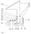
- the solar system shown in Fig. 1 has a solar collector 13, which in one Solar circuit circulating heat transfer medium warmed by solar radiation.
- a collector lead 1 is connected to the solar collector 13.
- the Collector flow 1 has a flow thermometer 2. Furthermore, flow 1 is on Dirt trap 3 arranged in the form of a fine filter.
- the collector flow 1 opens via a screw connection 4 in a heating or Drinking water storage arranged solar heat exchanger 5.
- the return of the Heat exchanger 5 is via a screw connection 6 with the collector return 12 connected.
- the collector return 12 is with a shut-off ball valve 7 provided and leads via a circulation pump 9, which acts as a gear pump is formed via a flow meter with a shut-off valve 10 and a Return thermometer 11 back to solar collector 13.
- a pipe branch is provided on which a flush valve 14, a pressure gauge 15 and a vent valve 16 are arranged. Furthermore, one is at one certain overpressure triggering safety valve 17 with an overflow 20th provided on the branch pipe. At the end of the branch pipe is by means of Coupling 18 connected to an expansion tank 19.
- the gear pump 9 designed according to the invention is shown in FIG Fig. 3 shown with the line A-B cut.
- the gear pump 9 has a pump housing 91 in which a pump chamber is formed, the two gears 93, 94 receives.
- the concentrically arranged gear 93 (see FIG. 4) is mounted on a drive axle 95.
- Gear 94 is meshed arranged with the gear 93 freely rotatable on a minor axis 96.
- the gear wheels 93, 94 are helically toothed.
- the drive axle 95 is one with the drive axle Canned motor 21 connected.
- the one equipped with the gear wheels 93, 94 Pump chamber is closed with a pump cover 92.
- the pump chamber introduces, as shown in Fig. 3, a suction port 98 and a Filling port 99.
- a pressure port 97 is provided on the pressure side of the pump.
- gear pumps are generally hydraulic as well as mechanical Generating noise are several measures to reduce noise emissions intended. Due to the helical toothing of the gear wheels 93 and 94 become a pulsating flow and related hydraulic Avoided noises.
- the outer surface 90 of the Pump housing 91 is structured in stages to reduce noise emissions to minimize over the pump housing. That is essentially cylindrical or pot-shaped pump housing 91 is in the form of stepped Cylinder surface graded with different radii, so that resonance phenomena greatly reduced on the outer surface 90 or completely switched off become.
- the solar system according to the invention can be operated directly via the fill and drain valve 8 are filled with the heat transfer medium.
- the filling tap 8 a storage tank for the heat transfer medium is connected.
- the heat transfer medium When the system is filled and properly vented via vent valve 16 the heat transfer medium is circulated in the system by means of the gear pump 9. The medium flows along the collector return 12 to the solar collector 13, where the sun's rays warm the medium. The heated heat transfer medium is then via the solar flow 1 and the fine filter 3 fed to the heat exchanger 5.
- the fine filter 3 is made of floating particles separate the heat transfer medium to ensure the operational safety of the gear pump 9 to ensure.
- the heat energy absorbed in the solar collector 13 is in the heat exchanger 5 from the heat transfer medium to the surrounding liquid, preferably Water, in the heating or drinking water tank through heat conduction issued.
- the heat transfer medium is then via the gear pump 9 again fed to the solar collector 13. With temperature fluctuations in the systems becomes more uniform by means of the expansion tank 19 Maintain pressure.
- the system is preferably operated at a pressure of 2 bar, the Safety valve 17 allows a maximum pressure of, for example, 4 bar.
- the flow rate of the pump should be about 150 l / h maximum.
- the pump is powered by the canned motor 21, which is connected to the drive shaft 95
- Gear pump 9 is flanged, driven directly.
- Gears 93 and 94 are helically toothed to ensure that they are as uniform as possible, i.e. H. not pulsating, To generate flow. Because the achievable delivery pressure and the slope the characteristic curve of the pump for gear pumps u. a. depends on the gap games, these are chosen so that a relatively flat characteristic curve is maintained of the required delivery pressure arises. So that becomes something poorer volumetric efficiency achieved, yet the advantages outweigh for universal use of the pump.
- the gear pump 9 In the absence of sunlight, the gear pump 9 is switched off and thus the circulation is interrupted. Due to the blocking effect of the used Gear pump at standstill is a recirculation of the heat transfer medium not possible. The gear pump 9 prevents any liquid movement. In order to are gravity traps or check valves in the circulation lines dispensable.
Landscapes
- Engineering & Computer Science (AREA)
- Mechanical Engineering (AREA)
- General Engineering & Computer Science (AREA)
- Sustainable Energy (AREA)
- Physics & Mathematics (AREA)
- Thermal Sciences (AREA)
- Chemical & Material Sciences (AREA)
- Combustion & Propulsion (AREA)
- Life Sciences & Earth Sciences (AREA)
- Sustainable Development (AREA)
- Electromagnetic Pumps, Or The Like (AREA)
- Structures Of Non-Positive Displacement Pumps (AREA)
- Rotary Pumps (AREA)
Claims (13)
- Installation solaire aveccaractérisée en ce queun circuit solaire d'un fluide caloporteur,un collecteur solaire (13) intégré dans ce circuit solaire,un échangeur de chaleur (5) dans le circuit solaire, etune pompe de circulation dans le circuit solaire qui est conçue comme une pompe à engrenages (9),
la pompe à engrenages (9) a une hauteur de refoulement comprise entre 10 m et 40 m et fournit un débit de refoulement compris entre 10 l/h et 200 l/h. - Installation solaire selon la revendication 1, caractérisée en ce que la pompe (9) a une courbe caractéristique de pompe plate.
- Installation solaire selon la revendication 1 ou 2, caractérisée en ce qu'un moteur à gaine (21) est prévu pour l'entraínement de la pompe à engrenages (9).
- Installation solaire selon la revendication 3, caractérisée en ce qu'une régulation de vitesse de rotation est prévue pour le moteur à gaine (21).
- Installation solaire selon l'une quelconque des revendications précédentes, caractérisée en ce que la pompe (9) comporte, du côté aspiration près d'un raccordement d'aspiration (98), un raccordement de remplissage (99) pour le remplissage de l'installation solaire avec le fluide caloporteur.
- Installation solaire selon l'une quelconque des revendications précédentes, caractérisée en ce que les engrenages (93,94) de la pompe ont une denture hélicoïdale.
- Installation solaire selon l'une quelconque des revendications précédentes, caractérisée en ce que le carter de pompe (91), le couvercle du carter de pompe (92) et/ou les engrenages (93,94) sont faits en matière plastique.
- Installation solaire selon l'une quelconque des revendications précédentes, caractérisée en ce qu'un filtre fin (3) est prévu dans le circuit solaire.
- Installation solaire selon l'une quelconque des revendications précédentes, caractérisée en ce que le carter de pompe (91) a une surface extérieure décrochée sur plusieurs étages (90).
- Pompe à engrenages (9), en particulier pour des installations solaires pour la circulation d'un fluide caloporteur, avec un carter de pompe (91), dans lequel deux engrenages sont logés de manière à tourner en prise l'un avec l'autre, et un couvercle de carter de pompe (92), caractérisée en ce que la pompe (9) a une courbe caractéristique de pompe plate.
- Pompe à engrenages selon la revendication 10, caractérisée en que le carter de pompe (91) a une surface extérieure décrochée sur plusieurs étages (90).
- Pompe à engrenages selon la revendication 10 ou 11, caractérisée en ce que les engrenages (93,94) ont une denture hélicoïdale.
- Pompe à engrenages selon la revendication 10, 11 ou 12, caractérisée en ce que le carter de pompe (91), le couvercle du carter de pompe (92) et/ou les engrenages (93,94) sont faits en matière plastique.
Priority Applications (1)
| Application Number | Priority Date | Filing Date | Title |
|---|---|---|---|
| DE1997119134 DE19719134A1 (de) | 1996-11-21 | 1997-05-07 | Zahnradpumpe |
Applications Claiming Priority (2)
| Application Number | Priority Date | Filing Date | Title |
|---|---|---|---|
| DE19543533A DE19543533C2 (de) | 1995-11-22 | 1995-11-22 | Solaranlage mit Zahnradpumpe |
| DE19543533 | 1995-11-22 |
Publications (3)
| Publication Number | Publication Date |
|---|---|
| EP0781969A2 EP0781969A2 (fr) | 1997-07-02 |
| EP0781969A3 EP0781969A3 (fr) | 1997-12-10 |
| EP0781969B1 true EP0781969B1 (fr) | 2003-04-23 |
Family
ID=7778122
Family Applications (1)
| Application Number | Title | Priority Date | Filing Date |
|---|---|---|---|
| EP96118682A Expired - Lifetime EP0781969B1 (fr) | 1995-11-22 | 1996-11-21 | Installation solaire avec pompe à engrenage |
Country Status (3)
| Country | Link |
|---|---|
| EP (1) | EP0781969B1 (fr) |
| AT (1) | ATE238525T1 (fr) |
| DE (2) | DE19543533C2 (fr) |
Families Citing this family (4)
| Publication number | Priority date | Publication date | Assignee | Title |
|---|---|---|---|---|
| DE19824543C5 (de) | 1998-06-03 | 2004-04-29 | Solvis Solarsysteme Gmbh | Verfahren zur Regelung von Umwälzpumpen in den Solarkollektorkreisen von Solaranlagen mit Speicher |
| AT3890U1 (de) * | 1999-09-28 | 2000-09-25 | Huemer Solar Gmbh | Selbstfüllende solaranlage |
| DE10115205A1 (de) * | 2001-03-27 | 2002-10-10 | Simplex Wilfer Gmbh & Co | Vorrichtung zum Spülen und/oder Befüllen eines Flüssigkeitskreislaufs einer Solaranlage |
| DE102007033659A1 (de) * | 2007-07-17 | 2009-01-22 | Cor Pumps + Compressors Ag | Stirnzahnradumwälzpumpe |
Family Cites Families (14)
| Publication number | Priority date | Publication date | Assignee | Title |
|---|---|---|---|---|
| DE1553116B2 (de) * | 1966-10-25 | 1971-07-15 | Licentia Patent Verwaltungs GmbH, 6000 Frankfurt | Elektromotorisch betriebene Zahnrad Ölpumpe |
| US3960322A (en) | 1974-12-17 | 1976-06-01 | Ruff John D | Solar heat pump |
| US4018581A (en) | 1974-12-17 | 1977-04-19 | John Denis Ruff | Solar heating system |
| DE2803118B2 (de) * | 1978-01-25 | 1980-07-31 | Stiebel Eltron Gmbh & Co Kg, 3450 Holzminden | Verfahren zur Beheizung mit einer Absorptionswärmepumpenanlage und Vorrichtung zur Durchführung des Verfahrens |
| US4238873A (en) | 1978-03-13 | 1980-12-16 | Entropy Limited | Apparatus for collecting and transporting heat energy |
| US4324227A (en) * | 1979-09-06 | 1982-04-13 | Mountain John F | Solar heat collecting panel |
| US4470776A (en) * | 1979-11-28 | 1984-09-11 | Commercial Shearing, Inc. | Methods and apparatus for gear pump lubrication |
| US4309148A (en) | 1979-12-07 | 1982-01-05 | Hare Louis R O | Pulsing steam solar water pump |
| DE3342385A1 (de) * | 1983-11-24 | 1985-06-05 | Montblanc-Simplo Gmbh, 2000 Hamburg | Zahnradpumpe |
| JPH01182585A (ja) * | 1988-01-13 | 1989-07-20 | Komatsu Ltd | プラスチック製ギヤポンプ |
| JPH0641755B2 (ja) * | 1989-04-19 | 1994-06-01 | 日機装株式会社 | キャンド内接ギヤポンプ |
| DE4102162A1 (de) * | 1991-01-25 | 1992-07-30 | Bosch Gmbh Robert | Vorrichtung zum foerdern von kraftstoff aus einem vorratstank zur brennkraftmaschine eines kraftfahrzeuges |
| DE9207743U1 (de) * | 1992-06-09 | 1992-11-19 | Schreiber, Ditmar, 6535 Gau-Algesheim | Regelungseinrichtung mit Leistungsanpassung für solarthermische Anlagen |
| DE4338604A1 (de) * | 1993-11-11 | 1995-05-18 | Sandler Energietechnik | Solarkollektor-Befüllung & Entleerung |
-
1995
- 1995-11-22 DE DE19543533A patent/DE19543533C2/de not_active Expired - Lifetime
-
1996
- 1996-11-21 AT AT96118682T patent/ATE238525T1/de not_active IP Right Cessation
- 1996-11-21 DE DE59610375T patent/DE59610375D1/de not_active Expired - Fee Related
- 1996-11-21 EP EP96118682A patent/EP0781969B1/fr not_active Expired - Lifetime
Also Published As
| Publication number | Publication date |
|---|---|
| ATE238525T1 (de) | 2003-05-15 |
| DE19543533A1 (de) | 1997-05-28 |
| EP0781969A2 (fr) | 1997-07-02 |
| DE59610375D1 (de) | 2003-05-28 |
| EP0781969A3 (fr) | 1997-12-10 |
| DE19543533C2 (de) | 1998-10-08 |
Similar Documents
| Publication | Publication Date | Title |
|---|---|---|
| DE112007000304B4 (de) | Kupplungsaggregat mit Nasslaufkupplung | |
| DE1528862A1 (de) | Abwasserpumpe od.dgl. | |
| DE19745616A1 (de) | Gekühlte Schraubenvakuumpumpe | |
| DE10331216B3 (de) | Fluidkühlvorrichtung | |
| DE2855085C2 (de) | Pumpenanordnung zur Versorgung von Verbrauchern mit stark schwankendem Bedarf an Druckflüssigkeit | |
| EP2171284A1 (fr) | Pompe a liquide | |
| EP3092405A1 (fr) | Dispositif de refroidissement et de lubrification et procédé de refroidissement et/ou de lubrification d'un engrenage destiné à une éolienne | |
| DE112004002502T5 (de) | System für unter inneren Überdruck gesetztes Hydraulikfluid mit entfernter Ladepumpe | |
| DE102020203984A1 (de) | Ölversorgungssystem eines Fahrzeuggetriebes | |
| AT409182B (de) | Anlage zur gewinnung von wärme aus solarenergie | |
| EP1132620B1 (fr) | Dispositif de transmission pour pompe de puits | |
| DE19543533C2 (de) | Solaranlage mit Zahnradpumpe | |
| DE10208688B4 (de) | Tauchmotorpumpe | |
| DE102016011503A1 (de) | System für ein Nutzfahrzeug umfassend einen Schraubenkompressor sowie einen Elektromotor | |
| DE102021110772B4 (de) | Zentrifugalkompressor mit einem Druckentlastungsdurchgang | |
| DE10117373A1 (de) | Hydraulisches Pumpenaggregat | |
| DE19529463A1 (de) | Solaranlage mit temperaturgesteuertem Entlastungsventil | |
| DE10222758A1 (de) | Kühlmittelpumpe für einen Kühlkreislauf einer Brennkraftmaschine und Drehschieberventil | |
| DE102005036347A1 (de) | Elektromotor mit koaxial zugeordneter Pumpe | |
| WO2012080034A2 (fr) | Pompe à vide | |
| DE3321380A1 (de) | Zahnradmaschine fuer selbstschmierende foerdermedien | |
| DE102006049663A1 (de) | Schraubenspindelpumpe mit Scheibenpumpen-Axiallager | |
| DE102007036032A1 (de) | Unterwassermotor mit Wärmetauscher | |
| DE102018208287A1 (de) | Vorrichtung zur Kühlung und Schmierung eines Getriebes für ein Fahrzeug | |
| EP1159553B1 (fr) | Dispositif d'entrainement hydraulique |
Legal Events
| Date | Code | Title | Description |
|---|---|---|---|
| PUAI | Public reference made under article 153(3) epc to a published international application that has entered the european phase |
Free format text: ORIGINAL CODE: 0009012 |
|
| AK | Designated contracting states |
Kind code of ref document: A2 Designated state(s): AT CH DE DK FR IT LI SE |
|
| PUAL | Search report despatched |
Free format text: ORIGINAL CODE: 0009013 |
|
| RHK1 | Main classification (correction) |
Ipc: F24D 11/00 |
|
| AK | Designated contracting states |
Kind code of ref document: A3 Designated state(s): AT CH DE DK FR IT LI SE |
|
| 17P | Request for examination filed |
Effective date: 19980514 |
|
| 17Q | First examination report despatched |
Effective date: 19991215 |
|
| TPAD | Observations filed by third parties |
Free format text: ORIGINAL CODE: EPIDOS TIPA |
|
| GRAH | Despatch of communication of intention to grant a patent |
Free format text: ORIGINAL CODE: EPIDOS IGRA |
|
| RIN1 | Information on inventor provided before grant (corrected) |
Inventor name: WUNDERLICH, ERHARD DR.ING. Inventor name: TERSCHUEREN, KLAUS-HENNING DIPL.ING. Inventor name: KRAUSE, THOMAS DIPL.ING. |
|
| GRAH | Despatch of communication of intention to grant a patent |
Free format text: ORIGINAL CODE: EPIDOS IGRA |
|
| GRAA | (expected) grant |
Free format text: ORIGINAL CODE: 0009210 |
|
| AK | Designated contracting states |
Designated state(s): AT CH DE DK FR IT LI SE |
|
| PG25 | Lapsed in a contracting state [announced via postgrant information from national office to epo] |
Ref country code: FR Free format text: LAPSE BECAUSE OF NON-PAYMENT OF DUE FEES Effective date: 20030423 |
|
| REG | Reference to a national code |
Ref country code: CH Ref legal event code: EP |
|
| RAP2 | Party data changed (patent owner data changed or rights of a patent transferred) |
Owner name: SOLVIS GMBH & CO. KG |
|
| REG | Reference to a national code |
Ref country code: CH Ref legal event code: NV Representative=s name: KELLER & PARTNER PATENTANWAELTE AG |
|
| REF | Corresponds to: |
Ref document number: 59610375 Country of ref document: DE Date of ref document: 20030528 Kind code of ref document: P |
|
| PG25 | Lapsed in a contracting state [announced via postgrant information from national office to epo] |
Ref country code: SE Free format text: LAPSE BECAUSE OF FAILURE TO SUBMIT A TRANSLATION OF THE DESCRIPTION OR TO PAY THE FEE WITHIN THE PRESCRIBED TIME-LIMIT Effective date: 20030723 Ref country code: DK Free format text: LAPSE BECAUSE OF FAILURE TO SUBMIT A TRANSLATION OF THE DESCRIPTION OR TO PAY THE FEE WITHIN THE PRESCRIBED TIME-LIMIT Effective date: 20030723 |
|
| PLBE | No opposition filed within time limit |
Free format text: ORIGINAL CODE: 0009261 |
|
| STAA | Information on the status of an ep patent application or granted ep patent |
Free format text: STATUS: NO OPPOSITION FILED WITHIN TIME LIMIT |
|
| 26N | No opposition filed |
Effective date: 20040126 |
|
| EN | Fr: translation not filed | ||
| PGFP | Annual fee paid to national office [announced via postgrant information from national office to epo] |
Ref country code: DE Payment date: 20071122 Year of fee payment: 12 |
|
| PGFP | Annual fee paid to national office [announced via postgrant information from national office to epo] |
Ref country code: CH Payment date: 20071019 Year of fee payment: 12 Ref country code: IT Payment date: 20071128 Year of fee payment: 12 Ref country code: AT Payment date: 20071130 Year of fee payment: 12 |
|
| REG | Reference to a national code |
Ref country code: CH Ref legal event code: PL |
|
| PG25 | Lapsed in a contracting state [announced via postgrant information from national office to epo] |
Ref country code: IT Free format text: LAPSE BECAUSE OF NON-PAYMENT OF DUE FEES Effective date: 20081121 Ref country code: AT Free format text: LAPSE BECAUSE OF NON-PAYMENT OF DUE FEES Effective date: 20081121 |
|
| PG25 | Lapsed in a contracting state [announced via postgrant information from national office to epo] |
Ref country code: LI Free format text: LAPSE BECAUSE OF NON-PAYMENT OF DUE FEES Effective date: 20081130 Ref country code: DE Free format text: LAPSE BECAUSE OF NON-PAYMENT OF DUE FEES Effective date: 20090603 Ref country code: CH Free format text: LAPSE BECAUSE OF NON-PAYMENT OF DUE FEES Effective date: 20081130 |