EP0782006B1 - Aktiv geschirmte supraleitende Magnetanordnung für die bildgebende magnetische Resonanz - Google Patents
Aktiv geschirmte supraleitende Magnetanordnung für die bildgebende magnetische Resonanz Download PDFInfo
- Publication number
- EP0782006B1 EP0782006B1 EP96309320A EP96309320A EP0782006B1 EP 0782006 B1 EP0782006 B1 EP 0782006B1 EP 96309320 A EP96309320 A EP 96309320A EP 96309320 A EP96309320 A EP 96309320A EP 0782006 B1 EP0782006 B1 EP 0782006B1
- Authority
- EP
- European Patent Office
- Prior art keywords
- coil support
- magnet
- coil
- magnet assembly
- key
- Prior art date
- Legal status (The legal status is an assumption and is not a legal conclusion. Google has not performed a legal analysis and makes no representation as to the accuracy of the status listed.)
- Expired - Lifetime
Links
- 238000002595 magnetic resonance imaging Methods 0.000 title description 14
- 229910000838 Al alloy Inorganic materials 0.000 claims description 10
- 239000004593 Epoxy Substances 0.000 claims description 10
- 238000006073 displacement reaction Methods 0.000 claims description 10
- 239000000463 material Substances 0.000 claims description 9
- 239000003365 glass fiber Substances 0.000 claims 1
- 229910001092 metal group alloy Inorganic materials 0.000 claims 1
- 229910052734 helium Inorganic materials 0.000 description 37
- 239000001307 helium Substances 0.000 description 37
- SWQJXJOGLNCZEY-UHFFFAOYSA-N helium atom Chemical compound [He] SWQJXJOGLNCZEY-UHFFFAOYSA-N 0.000 description 37
- 230000005291 magnetic effect Effects 0.000 description 16
- 230000008602 contraction Effects 0.000 description 6
- 239000011521 glass Substances 0.000 description 4
- 239000007788 liquid Substances 0.000 description 4
- XAGFODPZIPBFFR-UHFFFAOYSA-N aluminium Chemical compound [Al] XAGFODPZIPBFFR-UHFFFAOYSA-N 0.000 description 3
- 229910052782 aluminium Inorganic materials 0.000 description 3
- 238000010586 diagram Methods 0.000 description 3
- 238000003384 imaging method Methods 0.000 description 3
- 238000009434 installation Methods 0.000 description 3
- 238000004519 manufacturing process Methods 0.000 description 3
- 238000000034 method Methods 0.000 description 3
- XEEYBQQBJWHFJM-UHFFFAOYSA-N Iron Chemical compound [Fe] XEEYBQQBJWHFJM-UHFFFAOYSA-N 0.000 description 2
- 238000004804 winding Methods 0.000 description 2
- 230000001010 compromised effect Effects 0.000 description 1
- 238000001816 cooling Methods 0.000 description 1
- 230000000694 effects Effects 0.000 description 1
- 238000005516 engineering process Methods 0.000 description 1
- 230000007613 environmental effect Effects 0.000 description 1
- 230000005294 ferromagnetic effect Effects 0.000 description 1
- 229910052742 iron Inorganic materials 0.000 description 1
- 239000000696 magnetic material Substances 0.000 description 1
- 230000002093 peripheral effect Effects 0.000 description 1
- 239000010935 stainless steel Substances 0.000 description 1
- 229910001220 stainless steel Inorganic materials 0.000 description 1
- 230000001052 transient effect Effects 0.000 description 1
Images


Classifications
-
- G—PHYSICS
- G01—MEASURING; TESTING
- G01R—MEASURING ELECTRIC VARIABLES; MEASURING MAGNETIC VARIABLES
- G01R33/00—Arrangements or instruments for measuring magnetic variables
- G01R33/20—Arrangements or instruments for measuring magnetic variables involving magnetic resonance
- G01R33/28—Details of apparatus provided for in groups G01R33/44 - G01R33/64
- G01R33/38—Systems for generation, homogenisation or stabilisation of the main or gradient magnetic field
- G01R33/381—Systems for generation, homogenisation or stabilisation of the main or gradient magnetic field using electromagnets
- G01R33/3815—Systems for generation, homogenisation or stabilisation of the main or gradient magnetic field using electromagnets with superconducting coils, e.g. power supply therefor
-
- G—PHYSICS
- G01—MEASURING; TESTING
- G01R—MEASURING ELECTRIC VARIABLES; MEASURING MAGNETIC VARIABLES
- G01R33/00—Arrangements or instruments for measuring magnetic variables
- G01R33/20—Arrangements or instruments for measuring magnetic variables involving magnetic resonance
- G01R33/28—Details of apparatus provided for in groups G01R33/44 - G01R33/64
- G01R33/42—Screening
- G01R33/421—Screening of main or gradient magnetic field
-
- H—ELECTRICITY
- H01—ELECTRIC ELEMENTS
- H01F—MAGNETS; INDUCTANCES; TRANSFORMERS; SELECTION OF MATERIALS FOR THEIR MAGNETIC PROPERTIES
- H01F6/00—Superconducting magnets; Superconducting coils
Definitions
- This invention relates to support structures for superconducting magnets.
- the invention relates to structures for supporting magnet coils of an active magnetic shielding system.
- a coiled magnet if wound with wire possessing certain characteristics, can be made superconducting by placing it in an extremely cold environment, such as by enclosing it in a cryostat or pressure vessel containing liquid helium or other cryogen.
- the extreme cold reduces the resistance in the magnet coils to negligible levels, such that when a power source is initially connected to the coil (for a period, for example, of 10 minutes) to introduce a current flow through the coils, the current will continue to flow through the coils due to the negligible resistance even after power is removed, thereby maintaining a magnetic field.
- Superconducting magnets find wide application, for example, in the field of magnetic resonance imaging (hereinafter "MRI").
- the modern MRI system requires a high-strength uniform magnetic field in a large imaging volume, for example, a field having an inhomogeneity of a few parts per million over a spherical volume having a diameter of 40-50 cm.
- the signal-to-noise ratio of MRI is proportional to the field strength in the imaging region.
- the field strength for MRI is usually required to be larger than 0.5 T and up to 2 or 3 T.
- the stray field produced by such a magnet must be limited to a small volume to minimize the environmental impact of a magnet of such large size.
- a typical active shield magnet consists of two sets of superconducting coils.
- An inner set of coils usually called the main magnet coils, produce a uniform magnetic field of large magnitude in a imaging volume.
- the conventional support structure for the main magnet coils is a circular cylindrical aluminum drum.
- the main coils are wound separately around stainless steel bobbins, placed in grooves machined in the drum and spaced axially along the inside of the drum.
- Another set of outer magnet coils, usually called bucking coils are spaced from and surround the main coils, and are supported by a structure which is secured to the drum.
- the bucking coils carry currents in the direction opposite to the direction of currents being carried by the main coils so as to cancel the stray magnetic field outside the magnet. This is called active magnetic shielding.
- the support structure for the bucking coils be relatively lightweight and yet withstand the significant magnetic and thermal loads placed upon it during energization and operation of an MRI system. It is also important that the bucking coils maintain close positional accuracy, notwithstanding the significant thermal loads during initial operation or cooldown of the MRI, and notwithstanding the electromagnetic loads generated during energization and operation. As a result, there are conflicting thermal, magnetic and mechanical considerations and factors which must be balanced and compromised to obtain an acceptable bucking coil assembly.
- a conventional active shield magnet has a very complicated structure and has been expensive to build.
- An example of a known active shield magnet is described in U.S. Patent No. 5,237,300.
- a plurality of main magnet coils 4a-4f produce a highly uniform magnetic field of large magnitude.
- the main coils are supported by a circular cylindrical drum 2 within machined pockets or grooves.
- Drum 2 is typically made of aluminum alloy.
- a pair of bucking coils 10a and 10b concentrically surround portions of drum 2 and main magnet coils 4a-4f.
- the bucking coils carry currents in a direction opposite to the direction in which currents are carried by the main magnet coils, thereby providing cancellation of magnetic fields in the region outside the MRI system.
- the bucking coils are supported on bucking coil support cylinders or bands 6 and 8, respectively.
- the supports for the bucking coils include a plurality of struts or plates 12 extending angularly outward from drum 2, or from bands 16 around the drum, to bucking coil support cylinders 6 and 8, with spacing rods 14 extending axially between the bucking coil support cylinders.
- EP-A-0,414,528 describes a superconducting magnet which has ferromagnetic compensation rings positioned coaxially around its bore axis.
- the superconducting magnet coils are supported in circumferential grooves in a cylindrical coil former.
- EP-A-0,468,415 describes a magnet assembly according to the preamble of claim 1 for a superconducting magnet with coaxial inner and outer coils, each supported in circumferential grooves in coil-formers.
- a conducting ring is mounted outside the working volume to counter the effects of transient magnetic fields by producing an opposing field.
- the invention is an improved actively shielded superconducting magnet in which the main coils are directly wound onto the outer circumferential surface of a circular cylindrical coil support structure made of glass fiber-reinforced epoxy.
- the bucking coils are directly wound on the outer circumferential surface of another circular cylindrical coil support structure made of glass fiber-reinforce depoxy and having a diameter greater than the diameter of the main coil support structure.
- Several layers of aluminum overwrap tape are wrapped on top of the main and bucking coil windings to constrain radially outward displacement of the coils during magnetenergization.
- the main coil cartridge and the bucking coil cartridge are held in a fixed concentric relationship via a pair of flanges located at opposite ends of a helium vessel.
- the outer diameters of the respective coil support structures are machined with high precision.
- two concentric grooves are machined on the inner surface of each helium vessel end flange. The respective diameters of these two grooves are precisely machined to match the outer diameter of the main and bucking coil support structures, s so that at room temperature the main and bucking coil cartridges can slide smoothly into these grooves.
- the helium vessel is made of aluminum alloy and has a coefficient of thermal expansion which is greater than that of the fiber-reinforced epoxy coil support structures.
- the helium vessel end flanges hold the main and bucking coil cartridges tightly with a predetermined amount of interference due to differential contraction of the aluminum alloy and the fiber-reinforced epoxy materials. This not only provides mechanical support to the main and bucking coil cartridges, but also completely fixes the relative radial positions of the main and bucking coil cartridges so that their concentricity is assured.
- the relative axial positions of the main and bucking coil cartridges are fixed using the same working principle.
- the depth of the grooves on the helium vessel end flanges is also precisely machined.
- one of the helium vessel end flanges is first positioned in a flat platform.
- the main and bucking coil cartridges are each vertically inserted and seated on the flange grooves and then locked by a set of keys.
- the inner and outer cylinders and the other end flange of the helium vessel are then assembled and welded together.
- the axial differential contraction between the aluminum alloy helium vessel and the fiber-reinforced epoxy coil support structures will close any axial gaps between the helium vessel end flanges and the coil support structures and provide a firm support to the main and bucking coil cartridges.
- the helium vessel/magnet assembly is then installed in a typical cryogenic vacuum enclosure which is fitted with peripheral equipment to produce magnetic resonance images.
- FIG. 1 is a schematic diagram depicting a side sectional view of a conventional actively shielded superconducting magnet assembly.
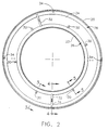
- FIG. 2 is a schematic diagram depicting an interior end view of a helium vessel/magnet assembly in accordance with the preferred embodiment of the invention.
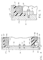
- FIGS. 3-5 are schematic diagrams depicting respective partial sectional views of the helium vessel/magnet assembly shown in FIG. 2, with the sections being taken along lines 3-3, 4-4 and 5-5, respectively.
- the magnet assembly in accordance with the preferred embodiment of the invention comprises a leaktight vessel filled with liquid helium or other cryogen (hereinafter “helium vessel”).
- the helium vessel comprises a pair of mutually parallel, opposed end flanges 24, only one of which is shown in the drawings.
- Each end flange is an annular plate, preferably fabricated from aluminum alloy.
- the helium vessel further comprises an outer cylindrical wall 20 and an inner cylindrical wall 22, also made of aluminum alloy. Walls 20 and 22 are mutually concentric, with wall 20 having a radius greater than that of wall 22. As seen in FIG.
- the ends of wall 20 are respectively welded to the outer peripheries of the end flanges 24 (weld W1), while the ends of wall 22 are respectively welded to the inner peripheries of the end flanges (weld W2).
- the final enclosed welded assembly has a generally toroidal shape.
- the helium vessel contains a main coil cartridge 26 and a bucking coil cartridge 28 (see FIG. 2). Both cartridges are generally circular cylindrical, with the radius of cartridge 28 being greater than the radius of the cartridge 26.
- the main coil cartridge 26 has an inner circumferential surface of radius greater than the radius of the outer circumferential surface of the helium vessel inner cylindrical wall 22.
- the bucking coil cartridge 28 has an outer circumferential surf ace of radius less than the radius of the inner circumferential surface of the helium vessel outer cylindrical wall 20.
- the main coil cartridge 26 comprises a main magnet coil support 27 and a plurality of main magnet coils (typically six or more) arranged in annular grooves formed on the outer circumferential surface of main magnet coil support 27.
- FIG. 3 shows only three of those main magnet coils designated 36a, 36b and 36c.
- the main magnet coils are directly wound on coil support 27 with specified tensions, typically 13.6 - 27.2 Kg (30-60 Ibs.).
- the bucking coil cartridge 28 comprises a bucking-magnet coil support 29 and a plurality of bucking magnet coils (typically two or more) arranged in annular grooves formed on the outer circumferential surface of bucking magnet coil support 29.
- FIG. 3 shows only one of those bucking magnet coils designated 38.
- the bucking magnet coils are directly wound on coil support 29 with the same specified tensions.
- the coil support structures 27 and 29 are both made of glass fiber-reinforced epoxy.
- Several layers of aluminum overwrap tape 40 (typically 4 to 8 layers) are wrapped on top of the main and bucking coil windings to constrain radially outward displacement of the coils during magnet energization.
- the coil supports 27 and 29 are held in a fixed concentric relationship by the end flanges 24 located at opposite ends of the helium vessel.
- the outer diameters of the respective coil supports 27 and 29 are machined with high precision.
- two concentric grooves are machined on the inner surface of each helium vessel end flange 24. The respective diameters of these two grooves are precisely machined to match the outer diameter of the main and bucking coil supports 27 and 29, so that at room temperature the main and bucking coil cartridges can slide smoothly into these grooves.
- main magnet coil support 27 The ends of main magnet coil support 27 are inserted in the smaller-radius annular grooves formed in the respective end flanges 24, and the ends of bucking magnet coil support 29 are inserted in the larger-radius annular grooves formed in the respective end flanges, as shown for one end flange in FIG. 3.
- the helium vessel is made of aluminum alloy and has a coefficient of thermal expansion which is greater than that of the fiber-reinforced epoxy coil support structures.
- the temperature of the helium vessel and magnet cartridges therein drops, causing the respective materials to contract.
- Due to differential contraction of the aluminum alloy and the glass fiber-reinforced epoxy the helium vessel contracts more than the coil supports.
- One result of this differential thermal contraction is that each helium vessel end flange 24 holds the main and bucking coil cartridges 26 and 28 tightly with a predetermined amount of interference. This provides mechanical support to the main and bucking coil cartridges, and also fixes the relative radial positions of the main and bucking coil cartridges so that their concentricity is assured.
- Another result of differential thermal contraction is that the relative axial positions of the main and bucking coil cartridges are fixed.
- the depth of the annular grooves on each end flange 24 is precisely machined.
- one of the helium vessel end flanges is placed flat on a platform.
- the main and bucking coil cartridges are each vertically inserted in a respective annular groove until the radial endfaces of the inserted ends of the coil supports are seated on the bottom walls of the annular grooves in the end flange.
- the main magnet coil cartridge 26 is then locked against the end flange 24 by installing a plurality of latches 30 around the circumference of the main magnet coil cartridge 26, as seen in FIG. 2.
- each latch 30 is attached to the end flange 24 by a threaded fastener 44.
- the latch 30 has a projection which abuts lip 27a when fastener 44 is fully tightened, so that at that location the projection blocks axial displacement of inner coil support 27 in a direction away from the end flange.
- Installation of a plurality of latches 30 at intervals around the circumference serves to lock the main magnet coil cartridge 26 against axial displacement relative to the end flange 24, as well as preventing yawing of cartridge 26 relative to the vessel centerline during subsequent assembly procedures.
- the bucking magnet coil cartridge 28 is held axially against the end flange 24 by means of a T-shaped key 34, shown in side profile in FIG. 4.
- the side of the key head confronting the end flange has a chamfer which defines a weld groove filled with weld material to form weld W3, by which key 34 and end flange 24 are joined.
- the shaft of key 24 fits snugly in a radial bore 46 of circular cross section which is machined in the bucking magnet coil support 28.
- a plurality of latches 34 at intervals around the circumference serves to lock the bucking magnet coil cartridge 28 against axial displacement relative to the end flange 24, as well as preventing yawing of cartridge 28 relative to the vessel centerline during subsequent assembly procedures.
- each key 32 is attached to the end flange 24 by means of a pair of threaded fasteners 42 (see FIG. 4).
- Key 32 is provided with a rounded radial slot 52, through which the shafts of fasteners 42 pass.
- one end of key 32 is interlocked with an axial groove 48 formed in lip 27a of inner coil support 27, and the other end of key 32 is interlocked with a radial groove 50 formed in the endface of outer coil support 29 which contacts the radially outer annular groove in the end flange.
- the inner cylindrical wall 22, the outer cylindrical wall 20 and the other end flange (not shown) of the helium vessel are assembled and welded together.
- the axial differential contraction between the aluminum alloy helium vessel and the fiber-reinforced epoxy coil supports will close any axial gaps between the helium vessel end flanges and the coil supports and provide a firm support to the main and bucking coil cartridges.
Landscapes
- Physics & Mathematics (AREA)
- Condensed Matter Physics & Semiconductors (AREA)
- General Physics & Mathematics (AREA)
- Electromagnetism (AREA)
- Engineering & Computer Science (AREA)
- Power Engineering (AREA)
- Health & Medical Sciences (AREA)
- Epidemiology (AREA)
- Magnetic Resonance Imaging Apparatus (AREA)
- Containers, Films, And Cooling For Superconductive Devices (AREA)
Claims (8)
- Magnetanordnung für einen supraleitenden Magneten, enthaltend einen Kryogenbehälter mit gegenüberliegenden ersten und zweiten Endflanschen (24), einer äusseren zylindrischen Wand (20) mit ersten und zweiten Enden, die auf entsprechende Weise mit den ersten und zweiten Endflanschen verbunden sind, einer inneren zylindrischen Wand (22) mit ersten und zweiten Enden, die auf entsprechende Weise mit den ersten und zweiten Endflanschen verbunden sind, wobei die innere zylindrische Wand (22) von der äusseren zylindrischen Wand (20) umgeben ist, eine kreiszylindrische innere Spulenhalterung (27) in dem Behälter für eine erste Magnetspule enthalten ist und eine kreiszylindrische äussere Spulenhalterung (29) in dem Behälter für eine zweite Magnetspule enthalten ist;dadurch gekennzeichnet, daßdie äussere Spulenhalterung eine erste Umfangsvertiefung aufweist, die in ihrer äusseren Oberfläche ausgebildet ist;die innere Spulenhalterung eine erste Umfangsvertiefung aufweist, die in ihrer äusseren Oberfläche ausgebildet ist;die erste Magnetspule, die durch die innere Spulenhalterung gehaltert ist, eine Hauptmagnetspule (36a,b,c) ist, die in der ersten Umfangsvertiefung angeordnet und direkt auf die innere Spulenhalterung gewickelt ist;die zweite Magnetspule, die durch die äussere Spulenhalterung gehaltert ist, eine Gegenmagnetspule (38) ist, die in der ersten Umfangsvertiefung angeordnet und direkt auf die äussere Spulenhalterung gewickelt ist;wobei die inneren und äusseren kreiszylindrischen Wände aus einem ersten Material hergestellt sind, das einen ersten thermischen Ausdehnungskoeffizienten hat, und die inneren und äusseren Spulenhalterungen aus einem zweiten Material hergestellt sind, das einen zweiten thermischen Ausdehnungskoeffizienten hat,der zweite thermische Ausdehnungskoeffizient kleiner als der erste thermische Ausdehnungskoeffizient ist;die ersten und zweiten Endflansche jeweils zueinander konzentrische erste und zweite ringförmige Vertiefungen haben, die auf einer inneren Fläche von ihnen ausgebildet sind, wobei die erste ringförmige Vertiefung einen Radius hat, der kleiner als der Radius der zweiten fingförmigen Vertiefung ist,die kreiszylindrische äussere Spulenhalterung erste und zweite Enden hat, die in die zweiten ringförmigen Vertiefungen der ersten bzw. zweiten Endflansche eingesetzt sind; unddie kreiszylindrische innere Spulenhalterung erste und zweite Enden hat, die in die ersten ringförmigen Vertiefungen der ersten bzw. zweiten Endflansche eingesetzt sind.
- Magnetanordnung nach Anspruch 1, wobei die äussere Spulenhalterung (29) eine zweite Umfangsvertiefung aufweist, die auf ihrer äusseren Oberfläche ausgebildet ist, und die innere Spulenhalterung (27) eine zweite Umfangsvertiefung aufweist, die auf ihrer äusseren Oberfläche ausgebildet ist, und wobei eine weitere Hauptmagnetspule in der zweiten Umfangsvertiefung in der inneren Spulenhalterung angeordnet ist und eine weitere Gegenmagnetspule in der zweiten Umfangsvertiefung in der äusseren Spulenhalterung angeordnet ist.
- Magnetanordnung nach Anspruch 1, wobei die ersten und zweiten Enden der äusseren zylindrischen Wand an einem radial äusseren Umfang der ersten bzw. zweiten Flansche angeschweißt sind (W1,W2) und die ersten und zweiten Enden der inneren zylindrischen Wand an einem radial inneren Umfang von den ersten bzw. zweiten Endflanschen angeschweißt sind.
- Magnetanordnung nach einem der vorstehenden Ansprüche, wobei eine Verriegelung (30) an dem ersten Endflansch durch ein mit Gewinde versehenes Befestigungsglied (44) befestigt ist, die Verriegelung einen Vorsprung hat, der an einem Abschnitt von der inneren Spulenhalterung anliegt und eine axiale Verschiebung von dem Abschnitt der inneren Spulenhalterung in einer Richtung von dem ersten Endflansch weg blockiert.
- Magnetanordnung nach einem der vorstehenden Ansprüche, wobei ein Keil (34) an dem ersten Endflansch angeschweißt ist (W3), der Keil einen Vorsprung hat, der in eine Vertiefung (46)passt, die in einem Abschnitt von der äusseren Spulenhalterung ausgebildet ist, und eine axiale Verschiebung von dem Abschnitt der äusseren Spulenhalterung in einer Richtung von dem ersten Endflansch weg blockiert.
- Magnetanordnung nach einem der vorstehenden Ansprüche, wobei ein Keil (32) an dem ersten Endflansch durch erste und zweite Gewinde-Befestigungsglieder (42) befestigt ist, wobei der Keil so geformt und angeordnet ist, daß ein erstes Ende von dem Keil in eine Vertiefung (48) in der inneren Spulenhalterung vorsteht und ein zweites Ende von dem Keil in eine Vertiefung (50) in der äusseren Spulenhalterung vorsteht, wobei der Keil eine relative Umfangsverschiebung von der zweiten Magnetspule und der ersten Magnetspule verhindert.
- Magnetanordnung nach einem der vorstehenden Ansprüche, wobei das erste Material eine Metalllegierung und das zweite Material ein verstärktes Epoxid ist.
- Magnetanordnung nach Anspruch 7, wobei das erste Material Aluminiumlegierung und das zweite Material ein mit Glasfaser verstärktes Epoxid ist.
Applications Claiming Priority (2)
| Application Number | Priority Date | Filing Date | Title |
|---|---|---|---|
| US581100 | 1995-12-29 | ||
| US08/581,100 US5668516A (en) | 1995-12-29 | 1995-12-29 | Simplified active shield superconducting magnet assembly for magnetic resonance imaging |
Publications (2)
| Publication Number | Publication Date |
|---|---|
| EP0782006A1 EP0782006A1 (de) | 1997-07-02 |
| EP0782006B1 true EP0782006B1 (de) | 2000-07-26 |
Family
ID=24323884
Family Applications (1)
| Application Number | Title | Priority Date | Filing Date |
|---|---|---|---|
| EP96309320A Expired - Lifetime EP0782006B1 (de) | 1995-12-29 | 1996-12-19 | Aktiv geschirmte supraleitende Magnetanordnung für die bildgebende magnetische Resonanz |
Country Status (4)
| Country | Link |
|---|---|
| US (1) | US5668516A (de) |
| EP (1) | EP0782006B1 (de) |
| JP (1) | JP3940454B2 (de) |
| DE (1) | DE69609483T2 (de) |
Families Citing this family (23)
| Publication number | Priority date | Publication date | Assignee | Title |
|---|---|---|---|---|
| EP1230560A1 (de) * | 2000-09-26 | 2002-08-14 | Koninklijke Philips Electronics N.V. | Gerät der bildgebenden magnetischen resonanz mit vertikalem feld und mit einer im hauptmagneten angeordneten konischen kavität |
| GB2425345B (en) | 2002-11-21 | 2007-03-14 | Ge Med Sys Global Tech Co Llc | Cryogen pressure vessel assembly for superconducting magnets |
| US6844801B2 (en) | 2003-03-21 | 2005-01-18 | Ge Medical Systems Global Technology Company, Llc | Methods and apparatus for adjusting center magnetic field of a magnetic field generator for MRI |
| US6859123B2 (en) * | 2003-04-03 | 2005-02-22 | Ge Medical Systems Global Technology Company, Llc | Methods and apparatus for positioning permanent magnetic blocks |
| US7001479B2 (en) * | 2003-04-03 | 2006-02-21 | Ge Medical Systems Global Technology Company, Llc | Methods and apparatus for assembling magnetized permanent magnetic blocks |
| GB2446974B (en) * | 2006-04-13 | 2009-01-14 | Siemens Magnet Technology Ltd | A solenoidal magnet structure |
| GB2440369B (en) * | 2006-07-27 | 2009-03-04 | Siemens Magnet Technology Ltd | A cryogenic magnet control system |
| US7498814B1 (en) * | 2007-10-31 | 2009-03-03 | General Electric Company | Magnet assembly for magnetic resonance imaging system |
| US9640308B2 (en) * | 2008-10-14 | 2017-05-02 | General Electric Company | High temperature superconducting magnet |
| US7924010B2 (en) * | 2009-03-25 | 2011-04-12 | General Electric Company | Apparatus for supporting and method for forming a support for a magnetic resonance imaging (MRI) magnet |
| JP5534713B2 (ja) * | 2009-05-20 | 2014-07-02 | 三菱電機株式会社 | 超電導マグネット |
| GB2471882B (en) * | 2009-07-16 | 2011-09-28 | Siemens Magnet Technology Ltd | Method of manufacturing a solenoidal magnet, and a solenoidal magnet structure |
| GB2480637B (en) * | 2010-05-26 | 2013-02-20 | Siemens Plc | Solenoidal magnets having supported outer coils |
| GB2490478B (en) * | 2011-04-20 | 2014-04-23 | Siemens Plc | Superconducting magnets with thermal radiation shields |
| US9322892B2 (en) | 2011-12-20 | 2016-04-26 | General Electric Company | System for magnetic field distortion compensation and method of making same |
| US9279871B2 (en) * | 2011-12-20 | 2016-03-08 | General Electric Company | System and apparatus for compensating for magnetic field distortion in an MRI system |
| GB2503190A (en) * | 2012-01-05 | 2013-12-25 | Siemens Plc | Structurally self-supporting superconducting magnet with support for shield coils |
| WO2013180802A1 (en) * | 2012-03-13 | 2013-12-05 | Massachusetts Institute Of Technology | No-insulation multi-width winding for high temperature superconducting magnets |
| US9274188B2 (en) * | 2012-11-30 | 2016-03-01 | General Electric Company | System and apparatus for compensating for magnetic field distortion in an MRI system |
| FR3047460B1 (fr) * | 2016-02-08 | 2018-02-16 | Continental Automotive France | Electrovanne de vehicule automobile |
| GB2568950B (en) | 2017-12-01 | 2021-08-11 | Siemens Healthcare Ltd | Electromagnet assembly |
| GB2587379B (en) * | 2019-09-26 | 2024-05-29 | Siemens Healthcare Ltd | Support structure for a superconducting coil |
| CN115547660A (zh) * | 2021-06-29 | 2022-12-30 | 西门子(深圳)磁共振有限公司 | 磁共振成像系统的超导磁体及其加工工具和加工方法 |
Family Cites Families (9)
| Publication number | Priority date | Publication date | Assignee | Title |
|---|---|---|---|---|
| US4680666A (en) * | 1986-04-07 | 1987-07-14 | General Electric Company | MR magnet wiring harness circuit |
| JPS6387710A (ja) * | 1986-09-30 | 1988-04-19 | Mitsubishi Electric Corp | 超電導巻線用巻枠 |
| US4771256A (en) * | 1987-04-02 | 1988-09-13 | General Electric Company | Integral shield for mr magnet |
| US5001447A (en) * | 1989-08-23 | 1991-03-19 | General Electric Company | Ferromagnetic compensation rings for high field strength magnets |
| GB9016183D0 (en) * | 1990-07-24 | 1990-09-05 | Oxford Magnet Tech | Magnet assembly |
| US5099215A (en) * | 1990-08-29 | 1992-03-24 | General Electric Company | Coupling device for a superconducting magnet |
| US5406204A (en) * | 1992-03-27 | 1995-04-11 | Picker International, Inc. | Integrated MRI gradient coil and RF screen |
| US5237300A (en) * | 1992-08-03 | 1993-08-17 | General Electric Company | Support structure for actively shielded superconducting magnets |
| US5410288A (en) * | 1993-01-04 | 1995-04-25 | General Electric Company | Persistent superconducting switch for a superconducting magnet for imaging human limbs |
-
1995
- 1995-12-29 US US08/581,100 patent/US5668516A/en not_active Expired - Lifetime
-
1996
- 1996-12-19 DE DE69609483T patent/DE69609483T2/de not_active Expired - Fee Related
- 1996-12-19 EP EP96309320A patent/EP0782006B1/de not_active Expired - Lifetime
- 1996-12-27 JP JP34918596A patent/JP3940454B2/ja not_active Expired - Fee Related
Also Published As
| Publication number | Publication date |
|---|---|
| JP3940454B2 (ja) | 2007-07-04 |
| DE69609483D1 (de) | 2000-08-31 |
| US5668516A (en) | 1997-09-16 |
| JPH09283322A (ja) | 1997-10-31 |
| EP0782006A1 (de) | 1997-07-02 |
| DE69609483T2 (de) | 2001-03-29 |
Similar Documents
| Publication | Publication Date | Title |
|---|---|---|
| US5668516A (en) | Simplified active shield superconducting magnet assembly for magnetic resonance imaging | |
| US5237300A (en) | Support structure for actively shielded superconducting magnets | |
| US4646045A (en) | Aperture sized disc shaped end caps of a ferromagnetic shield for magnetic resonance magnets | |
| US5291169A (en) | Open architecture magnetic resonance imaging superconducting magnet assembly | |
| EP0981057B1 (de) | Magnetanordnung für die bildgebende Magnetresonanz mit nichtleitender innerer Wand | |
| CA1198164A (en) | Electromagnet for nmr tomography | |
| EP0216404B1 (de) | Apparat zur Bilderzeugung mittels magnetischer Resonanz mit homogenisierenden magnetischen Elementen | |
| JP4079504B2 (ja) | 磁気共鳴イメージング・マグネット | |
| US5999075A (en) | Open magnet with shielding | |
| EP0971240B1 (de) | Heliumtank für supraleitenden Magnet mit offener Architektur für die bildgebende magnetische Resonanz | |
| EP1102078B1 (de) | Offene supraleitende einen Heliumbehälter integrierende Magnetanordnung | |
| EP0770883B1 (de) | Offener, durch kryogenes Fluid gekühlter Magnet für die Bilderzeugung durch magnetische Resonanz mit gleichförmigem Magnetfeld | |
| US5574417A (en) | Open MRI magnet with homogeneous imaging volume | |
| EP0309577B1 (de) | Verfahren zur Herstellung eines Schilds für NMR-Magnet | |
| US5179338A (en) | Refrigerated superconducting MR magnet with integrated gradient coils | |
| US5539366A (en) | Magnet having contoured pole faces for magnetic field homogeneity | |
| US5396208A (en) | Magnet system for magnetic resonance imaging | |
| US5696476A (en) | Open architecture magnetic resonance imaging superconducting magnet assembly | |
| US5084677A (en) | Magnetic field generating apparatus | |
| EP0770882B1 (de) | Offener supraleitender Magnet für die Bilderzeugung durch magnetische Resonanz mit Kühlung durch kryogenes Fluid | |
| US4743880A (en) | MRI magnet system having shield and method of manufacture | |
| US5225782A (en) | Eddy current free MRI magnet with integrated gradient coils | |
| US5594401A (en) | Closed superconductive magnet with uniform imaging volume | |
| US4622824A (en) | Cryostat suspension system | |
| EP0940687A2 (de) | Offene Magneteinrichtung mit Abschirmung |
Legal Events
| Date | Code | Title | Description |
|---|---|---|---|
| PUAI | Public reference made under article 153(3) epc to a published international application that has entered the european phase |
Free format text: ORIGINAL CODE: 0009012 |
|
| AK | Designated contracting states |
Kind code of ref document: A1 Designated state(s): DE GB NL |
|
| 17P | Request for examination filed |
Effective date: 19980102 |
|
| 17Q | First examination report despatched |
Effective date: 19980220 |
|
| GRAG | Despatch of communication of intention to grant |
Free format text: ORIGINAL CODE: EPIDOS AGRA |
|
| GRAG | Despatch of communication of intention to grant |
Free format text: ORIGINAL CODE: EPIDOS AGRA |
|
| GRAH | Despatch of communication of intention to grant a patent |
Free format text: ORIGINAL CODE: EPIDOS IGRA |
|
| GRAH | Despatch of communication of intention to grant a patent |
Free format text: ORIGINAL CODE: EPIDOS IGRA |
|
| GRAA | (expected) grant |
Free format text: ORIGINAL CODE: 0009210 |
|
| AK | Designated contracting states |
Kind code of ref document: B1 Designated state(s): DE GB NL |
|
| REF | Corresponds to: |
Ref document number: 69609483 Country of ref document: DE Date of ref document: 20000831 |
|
| EN | Fr: translation not filed | ||
| PLBE | No opposition filed within time limit |
Free format text: ORIGINAL CODE: 0009261 |
|
| STAA | Information on the status of an ep patent application or granted ep patent |
Free format text: STATUS: NO OPPOSITION FILED WITHIN TIME LIMIT |
|
| 26N | No opposition filed | ||
| REG | Reference to a national code |
Ref country code: GB Ref legal event code: IF02 |
|
| PGFP | Annual fee paid to national office [announced via postgrant information from national office to epo] |
Ref country code: DE Payment date: 20080131 Year of fee payment: 12 |
|
| PG25 | Lapsed in a contracting state [announced via postgrant information from national office to epo] |
Ref country code: DE Free format text: LAPSE BECAUSE OF NON-PAYMENT OF DUE FEES Effective date: 20090701 |
|
| PGFP | Annual fee paid to national office [announced via postgrant information from national office to epo] |
Ref country code: GB Payment date: 20121227 Year of fee payment: 17 |
|
| PGFP | Annual fee paid to national office [announced via postgrant information from national office to epo] |
Ref country code: NL Payment date: 20121225 Year of fee payment: 17 |
|
| REG | Reference to a national code |
Ref country code: NL Ref legal event code: V1 Effective date: 20140701 |
|
| GBPC | Gb: european patent ceased through non-payment of renewal fee |
Effective date: 20131219 |
|
| PG25 | Lapsed in a contracting state [announced via postgrant information from national office to epo] |
Ref country code: NL Free format text: LAPSE BECAUSE OF NON-PAYMENT OF DUE FEES Effective date: 20140701 |
|
| PG25 | Lapsed in a contracting state [announced via postgrant information from national office to epo] |
Ref country code: GB Free format text: LAPSE BECAUSE OF NON-PAYMENT OF DUE FEES Effective date: 20131219 |