EP0782009B1 - Verfahren zur Erzeugung eines Übertragungsbildes in Nuklearmedizin - Google Patents
Verfahren zur Erzeugung eines Übertragungsbildes in Nuklearmedizin Download PDFInfo
- Publication number
- EP0782009B1 EP0782009B1 EP95402819A EP95402819A EP0782009B1 EP 0782009 B1 EP0782009 B1 EP 0782009B1 EP 95402819 A EP95402819 A EP 95402819A EP 95402819 A EP95402819 A EP 95402819A EP 0782009 B1 EP0782009 B1 EP 0782009B1
- Authority
- EP
- European Patent Office
- Prior art keywords
- patient
- image
- energy
- detector
- range
- Prior art date
- Legal status (The legal status is an assumption and is not a legal conclusion. Google has not performed a legal analysis and makes no representation as to the accuracy of the status listed.)
- Expired - Lifetime
Links
- 230000005540 biological transmission Effects 0.000 title claims description 28
- 238000000034 method Methods 0.000 title claims description 23
- 238000009206 nuclear medicine Methods 0.000 title description 10
- 230000005855 radiation Effects 0.000 claims description 40
- 230000002285 radioactive effect Effects 0.000 claims description 30
- 239000003550 marker Substances 0.000 claims description 21
- 230000001678 irradiating effect Effects 0.000 claims description 4
- 210000004072 lung Anatomy 0.000 claims description 4
- BKVIYDNLLOSFOA-UHFFFAOYSA-N thallium Chemical compound [Tl] BKVIYDNLLOSFOA-UHFFFAOYSA-N 0.000 claims description 4
- 229910052716 thallium Inorganic materials 0.000 claims description 4
- 239000003814 drug Substances 0.000 claims description 3
- 230000008569 process Effects 0.000 claims description 2
- 238000003384 imaging method Methods 0.000 claims 5
- GKLVYJBZJHMRIY-OUBTZVSYSA-N Technetium-99 Chemical compound [99Tc] GKLVYJBZJHMRIY-OUBTZVSYSA-N 0.000 claims 1
- 229940056501 technetium 99m Drugs 0.000 claims 1
- 229910052713 technetium Inorganic materials 0.000 description 9
- GKLVYJBZJHMRIY-UHFFFAOYSA-N technetium atom Chemical compound [Tc] GKLVYJBZJHMRIY-UHFFFAOYSA-N 0.000 description 9
- 238000002474 experimental method Methods 0.000 description 6
- 238000001514 detection method Methods 0.000 description 5
- 210000000056 organ Anatomy 0.000 description 4
- 238000003325 tomography Methods 0.000 description 4
- 208000031968 Cadaver Diseases 0.000 description 3
- 238000012937 correction Methods 0.000 description 3
- 239000013078 crystal Substances 0.000 description 3
- 238000012545 processing Methods 0.000 description 3
- 239000003124 biologic agent Substances 0.000 description 2
- 230000000694 effects Effects 0.000 description 2
- 230000004807 localization Effects 0.000 description 2
- 210000003484 anatomy Anatomy 0.000 description 1
- 230000008901 benefit Effects 0.000 description 1
- 239000008280 blood Substances 0.000 description 1
- 210000004369 blood Anatomy 0.000 description 1
- 238000004364 calculation method Methods 0.000 description 1
- 230000008859 change Effects 0.000 description 1
- 239000003795 chemical substances by application Substances 0.000 description 1
- 238000004590 computer program Methods 0.000 description 1
- 239000012141 concentrate Substances 0.000 description 1
- 230000007423 decrease Effects 0.000 description 1
- 230000003247 decreasing effect Effects 0.000 description 1
- 238000003745 diagnosis Methods 0.000 description 1
- 238000010586 diagram Methods 0.000 description 1
- 239000004744 fabric Substances 0.000 description 1
- 238000002347 injection Methods 0.000 description 1
- 239000007924 injection Substances 0.000 description 1
- 230000003993 interaction Effects 0.000 description 1
- 210000004185 liver Anatomy 0.000 description 1
- 238000004519 manufacturing process Methods 0.000 description 1
- 230000001902 propagating effect Effects 0.000 description 1
- 238000009877 rendering Methods 0.000 description 1
- 230000004044 response Effects 0.000 description 1
- 238000012552 review Methods 0.000 description 1
- 230000011218 segmentation Effects 0.000 description 1
- 238000002603 single-photon emission computed tomography Methods 0.000 description 1
- 239000000243 solution Substances 0.000 description 1
- 238000012360 testing method Methods 0.000 description 1
- 239000002699 waste material Substances 0.000 description 1
Images

Classifications
-
- G—PHYSICS
- G01—MEASURING; TESTING
- G01T—MEASUREMENT OF NUCLEAR OR X-RADIATION
- G01T1/00—Measuring X-radiation, gamma radiation, corpuscular radiation, or cosmic radiation
- G01T1/29—Measurement performed on radiation beams, e.g. position or section of the beam; Measurement of spatial distribution of radiation
- G01T1/2914—Measurement of spatial distribution of radiation
- G01T1/2985—In depth localisation, e.g. using positron emitters; Tomographic imaging (longitudinal and transverse section imaging; apparatus for radiation diagnosis sequentially in different planes, steroscopic radiation diagnosis)
-
- A—HUMAN NECESSITIES
- A61—MEDICAL OR VETERINARY SCIENCE; HYGIENE
- A61B—DIAGNOSIS; SURGERY; IDENTIFICATION
- A61B6/00—Apparatus or devices for radiation diagnosis; Apparatus or devices for radiation diagnosis combined with radiation therapy equipment
- A61B6/02—Arrangements for diagnosis sequentially in different planes; Stereoscopic radiation diagnosis
- A61B6/03—Computed tomography [CT]
- A61B6/037—Emission tomography
-
- F—MECHANICAL ENGINEERING; LIGHTING; HEATING; WEAPONS; BLASTING
- F02—COMBUSTION ENGINES; HOT-GAS OR COMBUSTION-PRODUCT ENGINE PLANTS
- F02F—CYLINDERS, PISTONS OR CASINGS, FOR COMBUSTION ENGINES; ARRANGEMENTS OF SEALINGS IN COMBUSTION ENGINES
- F02F1/00—Cylinders; Cylinder heads
- F02F1/02—Cylinders; Cylinder heads having cooling means
- F02F1/10—Cylinders; Cylinder heads having cooling means for liquid cooling
- F02F1/108—Siamese-type cylinders, i.e. cylinders cast together
-
- G—PHYSICS
- G01—MEASURING; TESTING
- G01T—MEASUREMENT OF NUCLEAR OR X-RADIATION
- G01T1/00—Measuring X-radiation, gamma radiation, corpuscular radiation, or cosmic radiation
- G01T1/16—Measuring radiation intensity
- G01T1/161—Applications in the field of nuclear medicine, e.g. in vivo counting
- G01T1/164—Scintigraphy
- G01T1/1641—Static instruments for imaging the distribution of radioactivity in one or two dimensions using one or several scintillating elements; Radio-isotope cameras
- G01T1/1642—Static instruments for imaging the distribution of radioactivity in one or two dimensions using one or several scintillating elements; Radio-isotope cameras using a scintillation crystal and position sensing photodetector arrays, e.g. ANGER cameras
Definitions
- the subject of the present invention is a method acquisition, in nuclear medicine, of an image in transmission of the body of a patient under examination.
- the image in transmission thus obtained can be used as which to reveal the anatomy of the body examined. Of preferably it will be used to correct results of a broadcast image revealed by the same machine.
- the advantage of the invention is that in this last case it is possible to acquire simultaneously the two images, hence saving time, and above all a much better geometric comparison of the two images acquired to be able to correct the results of one based on those of the other.
- Nuclear medicine is a discipline of medical diagnosis in which one seeks to obtain functional information from the patient's body examined.
- patients are injected with radioactive markers, usually these are Technetium.
- This radioactive marker depending on the biological agent which carries it, will settle in a organ or in another of the patient. Where it is fixed it emits radioactive radiation: rays gamma, the number of which is all the greater as a greater quantity of markers is fixed in the organ. This is an emission phenomenon.
- a nuclear medicine machine therefore involves basically a stand to support such gamma camera.
- This includes a detector and means of calculating the detected image.
- the detector features a scintillator crystal.
- the scintillator crystal is plane.
- the scintillator absorbs gamma radioactive radiation. By effect photoelectric, it emits a scintillation in response light, detected downstream by a network of tubes detector photo-multipliers.
- a gamma camera additionally includes a control console and treatment. The tubes are thus associated with means Calculation. These are used to determine the coordinates of a place of interaction of radiation gamma in the scintillator. This place is indicative of the projected image of the body.
- this localization can only be carried out interposing between the body and the scintillator a collimator.
- This collimator only lets through radioactive radiation propagating in a chosen direction.
- the mode of acquisition thus briefly recalled has one drawback, however: gamma rays emitted by the internal structures of the body must, before going to excite the scintillator, cross other regions of this body and they undergo a corresponding attenuation. This disturbs the acquisition of the acquired images, and the accuracy and the accuracy of the reconstructed images. Many attempts have been made to take into account this attenuation, sometimes without really measuring it. However, the methods thus proposed are proved unsuccessful, and to date the actual measure attenuation, in particular by tomography of transmission, is the only solution that seems possible. Knowing by such a method, in each place of the body, the attenuation coefficient linked to the radiological density, we can correct the emission image results. We take into account for the correction of the greater or lesser mass of fabrics that have been interposed on the way to a radioactive emission resulting from a disintegration of the marker pen.
- the first drawback is that subject the patient's body to a first irradiation with this external source and so there are a waste of time.
- the second drawback comes from the conical nature of the radiation. Indeed, because of limited detector sizes, the entire body of the patient cannot be included in the cone of radiation. Some parts of the body, close to cone generators are not usefully subjected to only when these parts are found most close to the detector plane. For reasons acquisition of a tomographic image, the gamma-camera turned half a turn around the body of the patient. These same regions are then the most distant from the detector plane and either are not irradiated, either are irradiated but the result of this irradiation exceeds the limits of the detector.
- the open energy window to measure photons Compton was centered on 110 Kev and had a width plus or minus 15%: from 94 to 127 Kev.
- the limit lower energy of Compton photons taken into account is 90 Kev (180 ° backscatter) and that by elsewhere, for detection reasons, it is accepted to open a window of plus or minus 10% around 140 Kev (126 Kev - 154 Kev) to measure radiation primary gamma, we can consider that this experiment took into account all photons Compton possible. Nevertheless, the conclusions drawn by the authors of the article make that reconstruction of contours with an internal source is difficult, and even is not effective enough to perform a quantitative assessment.
- the problem is therefore to be able to do without a external source, the manipulation of which is otherwise still dangerous for the manipulators, and that is the reason for wasted time and therefore profitability of the machine.
- the idea of the invention is however to use the source of gamma radiation, as it is injected into the patient, to acquire an image of transmission, at the same time as the image is acquired emission due to the radioactive marker.
- the invention rather than opening a window of energy tending to take photons into account Compton primaries, which are a priori the most numerous, on the contrary, we chose to take into account the secondary or even tertiary Compton photons in lowering the energy window so that part notable of it is located beyond the limit lower emission of primary Compton photons. For example, for primary Compton photons produced by Technetium this limit is 90 Kev.
- Figures 1 and 2 show a nuclear medicine, also called gamma-camera, usable to implement the method of the invention.
- the Figure 1 is a front view
- Figure 2 is a section from the view of Figure 1 in a vertical plane perpendicular to this figure 1.
- the machine has a frame 1 which maintains a stand 2.
- the stand 2 is held on the frame 1 by a rotation shaft 3 can rotate, in the direction of the arrows around a axis 4.
- Stand 2 maintains, in this example, two detectors 5 and 6 separated from each other to receive between them the body 7 of a patient placed on a bed 8.
- the machine could nevertheless have only one detector, or more than two. We know machines with thus up to twenty detectors.
- the principle of image acquisition is following.
- the gamma rays from this body pass through a collimator 9 (figure 3) placed on one side of the detector facing the body 7.
- the collimator 9 can be with straight holes or oblique, parallel or converging. The presence of a collimator avoids taking into account a annoying scattered radiation.
- the gamma photons that have the right direction of propagation come cause a scintillation s in a 10 scintillator crystal on the other side of the collimator 9.
- the scintillation s produced by the scintillator 10 is detected by a network 11 of photo-multiplier tubes such as 12 which produce electrical signals corresponding to the scintillation they detected. These signals are transmitted to processing circuits comprising in particular a barycentration resistance network 13 to weight the electrical signals produced by different tubes to develop signals electric locators called X +, X-, Y + and Y-representative of a place in the scintillator 10 where the scintillation measured occurred.
- the network of resistors 13 is connected to a circuit amplifier 14 which processes these electrical signals of location.
- Circuit 14 also produces a signal of energy W allowing, for each scintillation s of know his total energy.
- buttons 15 can just be a keyboard of a machine control computer, and display 16 screen 17 on this computer.
- buttons 15 can just be a keyboard of a machine control computer, and display 16 screen 17 on this computer.
- ways to indicate what the range is of energy to take into account For example for images in emission with a radioactive marker of the type Technetium emitting gamma photons at 140 Kev, it is classic to center the receiving energy window on 140 Kev and open it more or less 10%: between 154 Kev and 126 Kev.
- the device 19 for adjusting this range of energy is coupled to a filter circuit 18 which validates the taking into account, following the treatment carried out by the gamma camera, signals from localization if the energy of the gamma pulse measured is in the chosen range.
- buttons 15 the range so that it is located between 0.75 E and 0.35 E, E being the energy of the gamma rays normally emitted by the radioactive marker used.
- the setting of this range must in practice correspond essentially to the range of type reissues Compton at least secondary or tertiary. It is believed that by acting this way, we are sure to obtain an equal statistical distribution of the places of reissue. Indeed, we can estimate that the density of primary Compton re-emissions is decreasing at as one moves away from the ray source gamma, as we move away from the organ that has been injected in the body. By cons with regard to radiation secondary or primary, it would seem that their distribution be better. In any case, it leads, as we have seen from experience, at a better rendering of images. In particular the contours which do not appear in the cited article are now well revealed.
- Each detector therefore comprises downstream of the circuit 14 a circuit 18 which has two missions.
- it produces electrical signals X and Y which provide information on the exact position in the image produced of the place of the scintillation s (and therefore in correspondence of the place, in projection, where the gamma emission occurred primary or primary Compton radiation, secondary, tertiary in the body 7).
- Detection of this event results in the revelation on the screen 17 for viewing images from a light point to the location of the image that corresponds to these coordinates X, Y.
- this revelation is not done on the other hand that if otherwise the energy W measured corresponds to the range adjusted with the buttons 15. If the energy measured corresponds to this range, the circuit 19 for selecting window delivers a signal which confirms the operation of circuit 18. Otherwise it will not produces nothing: the radioactive event is ignored.
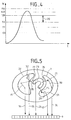
- Figure 4 shows an evolving energy signal W as a function of time when a scintillation.
- the duration of the electrical pulse delivered by tubes 12 for each scintillation is very short: on the order of a few nanoseconds. During this time the electrical signal increases then decreases to return to zero. If it is a primary gamma radiation due to Technetium this pulse should normally peak with a value corresponding to 140 Kev. Also, to reveal images in emission (where we take gamma radiation into account primary) we set the detection window between 126 Kev and 154 Kev. Primary Compton radiation, for the same marker produces gamma rays, the energy is not less than 90 Kev. The part of the range of figure 4 marked by the double arrow 20 was the part of energy scrutinized by experiments described in the article cited above and which led to the rejection of the technique.
- the invention provides that, on the contrary, very good results from the moment we center the detection window beyond the lower limit value of primary Compton radiation.
- the state-of-the-art gamma cameras are normally designed to be able to adjust with the device 19 a window corresponding to the Technetium: 140 Kev. They are also designed to set the reception on an energy window corresponding to Thallium: 70 Kev.
- the protocols Thallium acquisition costs are normally preprogrammed in all machines, to set work, to reveal the transmission image, the Thallium protocol while the injected marker in the body is Technetium. Therefore there is no nothing to change in existing machines for their reveal the transmission image acquired according to the method of the invention. You just have to choose a range of energy as mentioned above.
- double circuit 19 When you want to acquire both images, transmission and transmission simultaneously, we choose to double circuit 19 either physically and in this case we will also double circuit 18, that is, preferably, we modify the treatment program implemented by the image processing computer used by the machine.
- a machine for nuclear medicine records, for a given period, at each image point of an image to be created, the number radioactive events that have occurred there. The brightness of the points of the image is a function of this number. This distribution of luminosity reveals the contours of the body image.
- the machine image processing system has a computer program that increments the unit by one number of events assigned to a location X, Y in the image each time it receives X, Y signals delivered by circuit 18.
- the signals delivered by circuit 18, either will duplicated because there will be two circuits 18, either of preference will be supplemented by information g relative to the range and which will be given by the circuits 19.
- FIG. 5 shows a schematic representation of what's happening inside the body 7 of patient for the duration of the acquisition.
- the lungs 21 and 22 we distinguishes in this figure the lungs 21 and 22 as well as the heart 23 shown in section. Because of the agent biological used, we can estimate that only the heart 23, at least for the first time, is a transmitter of primary gamma radiation.
- Gamma rays primaries 24 will thus attack collimator 9. If they have the right orientation they cross the collimator and are taken into account to reveal the presence of the heart in the emission image.
- each segmented image element is assigned an attenuation coefficient corresponding to the biological tissues identified. This correspondence is preferably a priori. For example it is 0.15 cm -1 for biological tissue, 0.18 cm -1 for blood, 0.4 cm -1 for the lungs.
Landscapes
- Engineering & Computer Science (AREA)
- Health & Medical Sciences (AREA)
- Life Sciences & Earth Sciences (AREA)
- Physics & Mathematics (AREA)
- High Energy & Nuclear Physics (AREA)
- Molecular Biology (AREA)
- Medical Informatics (AREA)
- Optics & Photonics (AREA)
- Biomedical Technology (AREA)
- General Health & Medical Sciences (AREA)
- Spectroscopy & Molecular Physics (AREA)
- Nuclear Medicine, Radiotherapy & Molecular Imaging (AREA)
- General Physics & Mathematics (AREA)
- Heart & Thoracic Surgery (AREA)
- Veterinary Medicine (AREA)
- Radiology & Medical Imaging (AREA)
- Biophysics (AREA)
- Surgery (AREA)
- Animal Behavior & Ethology (AREA)
- Public Health (AREA)
- Pathology (AREA)
- Chemical & Material Sciences (AREA)
- Combustion & Propulsion (AREA)
- Mechanical Engineering (AREA)
- General Engineering & Computer Science (AREA)
- Nuclear Medicine (AREA)
- Cylinder Crankcases Of Internal Combustion Engines (AREA)
Claims (9)
- Verfahren zur nuklearmedizinischen Erzeugung eines auf der Transmission eines Körpers (7) beruhenden Bilds eines Patienten, umfassend die Schritte:Einbringen des Körpers (7) des Patienten in eine nuklearmedizinische Vorrichtung;Injizieren eines strahlenden Markers, der radioaktive Strahlen in einem vorbestimmten Energiebereich E emittiert, in den Körper (7) dieses Patienten; und dadurch gekennzeichnet, daß es ferner einen Schritt umfaßt, gemäß demmit einer Erfassungseinrichtung (5, 6) dieser nuklearmedizinischen Vorrichtung Strahlung erfaßt wird, die im Innern des Körpers (7) des Patienten entsteht und deren Energiebereich zwischen 0,75 E und 0,35 E liegt.
- Verfahren zur nuklearmedizinischen Erzeugung eines auf der Transmission eines Körpers (7) beruhenden Bilds eines Patienten, umfassend die Schritte:Einbringen des Körpers (7) des Patienten in eine nuklearmedizinische Vorrichtung;Injizieren eines strahlenden Markers, der radioaktive Strahlen in einem vorbestimmten Energiebereich E emittiert, in den Körper (7) dieses Patienten; und dadurch gekennzeichnet, daß es ferner einen Schritt erfaßt, gemäß demmit einer Erfassungseinrichtung (5, 6) dieser nuklearmedizinischen Vorrichtung Strahlung erfaßt wird, die im Innern des Körpers (7) des Patienten entsteht und deren Energie im wesentlichen der des Bereichs der zumindest sekundären (33, 34, 35, 36) oder tertiären (37) Compton-Reemissionen entspricht.
- Verfahren nach einem der Ansprüche 1 oder 2, dadurch gekennzeichnet, daßmit einer Erfassungsvorrichtung (5, 6) dieser nuklearmedizinischen Vorrichtung Strahlung erfaßt wird, die im Innern des Körpers des Patienten entsteht und deren Energiebereich zwischen 0,55 E und 0,45 E liegt.
- Verfahren nach einem der Ansprüche 1 bis 3, dadurch gekennzeichnet, daßdas Transmissionsbild gleichzeitig mit einem Sendebild erzeugt wird, indem in der aus dem Körper (7) des Patienten austretenden Strahlung diejenige, die zwischen 0,35 E und E liegt, gemessen wird, und indem diejenige, die der Energie E entspricht, abgetrennt wird, um das Strahlungsbild derjenigen, die dem Sendeenergiebereich entspricht, zu erzeugen.
- Verfahren nach einem der Ansprüche 1 bis 4, dadurch gekennzeichnet, daßein Technetium 99m enthaltender Marker injiziert wird und zum Erhalt des Transmissionsbilds die Strahlung erfaßt wird, die in einem Thallium entsprechenden Energiebereich entsteht.
- Verfahren nach einem der Ansprüche 1 bis 5, dadurch gekennzeichnet, daßwährend der Erzeugung die Erfassungseinrichtung mehrere um den Körper (7) des Patienten liegende Positionen einnimmt, undein tomographisches Bild der radiologischen Dichte von Gewebe im Innern dieses Körpers (7) abgeleitet wird.
- Verfahren nach Anspruch 6, dadurch gekennzeichnet, daßdas tomographische Bild der radiologischen Dichte segmentiert wird, indem je nachdem, wie die für diese Elemente gemessene Dichte von einem Bereich umfaßt wird, jedem Bildelement dieses Bilds Dichten eines gegebenen Typs zugewiesen werden.
- Verfahren nach einem der Ansprüche 6 oder 7, dadurch gekennzeichnet, daßdas Sendebild in Abhängigkeit von den Ergebnissen des Transmissionsbilds korrigiert wird.
- Verfahren nach einem der Ansprüche 1 bis 9, dadurch gekennzeichnet, daß der radioaktive Marker derart injiziert wird, daß er sich im Herzen (23) oder in der Lunge (21, 22) des Patienten festsetzt.
Priority Applications (8)
| Application Number | Priority Date | Filing Date | Title |
|---|---|---|---|
| FR9407332A FR2721411B1 (fr) | 1994-06-15 | 1994-06-15 | Procédé d'acquisition en médecine nucléaire d'une image en transmission. |
| US08/461,620 US5648659A (en) | 1994-06-15 | 1995-06-05 | Method for the acquisition, in nuclear medicine, of a scatter image |
| CA002164263A CA2164263A1 (fr) | 1994-06-15 | 1995-12-01 | Procede d'acquisition en medecine nucleaire d'une image en transmission |
| DE1995602959 DE69502959T2 (de) | 1995-12-14 | 1995-12-14 | Verfahren zur Erzeugung eines Übertragungsbildes in Nuklearmedizin |
| EP95402819A EP0782009B1 (de) | 1994-06-15 | 1995-12-14 | Verfahren zur Erzeugung eines Übertragungsbildes in Nuklearmedizin |
| AT95402819T ATE167307T1 (de) | 1995-12-14 | 1995-12-14 | Verfahren zur erzeugung eines übertragungsbildes in nuklearmedizin |
| JP7349886A JPH09178858A (ja) | 1994-06-15 | 1995-12-21 | 核医学における透過画像の獲得方法 |
| JP07337605A JP3057421B2 (ja) | 1994-06-15 | 1995-12-26 | サイアミーズシリンダの冷却装置 |
Applications Claiming Priority (5)
| Application Number | Priority Date | Filing Date | Title |
|---|---|---|---|
| FR9407332A FR2721411B1 (fr) | 1994-06-15 | 1994-06-15 | Procédé d'acquisition en médecine nucléaire d'une image en transmission. |
| CA002164263A CA2164263A1 (fr) | 1994-06-15 | 1995-12-01 | Procede d'acquisition en medecine nucleaire d'une image en transmission |
| EP95402819A EP0782009B1 (de) | 1994-06-15 | 1995-12-14 | Verfahren zur Erzeugung eines Übertragungsbildes in Nuklearmedizin |
| JP7349886A JPH09178858A (ja) | 1994-06-15 | 1995-12-21 | 核医学における透過画像の獲得方法 |
| JP07337605A JP3057421B2 (ja) | 1994-06-15 | 1995-12-26 | サイアミーズシリンダの冷却装置 |
Publications (2)
| Publication Number | Publication Date |
|---|---|
| EP0782009A1 EP0782009A1 (de) | 1997-07-02 |
| EP0782009B1 true EP0782009B1 (de) | 1998-06-10 |
Family
ID=27508587
Family Applications (1)
| Application Number | Title | Priority Date | Filing Date |
|---|---|---|---|
| EP95402819A Expired - Lifetime EP0782009B1 (de) | 1994-06-15 | 1995-12-14 | Verfahren zur Erzeugung eines Übertragungsbildes in Nuklearmedizin |
Country Status (5)
| Country | Link |
|---|---|
| US (1) | US5648659A (de) |
| EP (1) | EP0782009B1 (de) |
| JP (2) | JPH09178858A (de) |
| CA (1) | CA2164263A1 (de) |
| FR (1) | FR2721411B1 (de) |
Families Citing this family (7)
| Publication number | Priority date | Publication date | Assignee | Title |
|---|---|---|---|---|
| FR2721411B1 (fr) * | 1994-06-15 | 1996-08-23 | Sopha Medical | Procédé d'acquisition en médecine nucléaire d'une image en transmission. |
| US5689115A (en) * | 1995-11-24 | 1997-11-18 | Elscint Ltd. | Advanced nuclear medicine system |
| JP2001164985A (ja) | 1999-09-28 | 2001-06-19 | Kubota Corp | 多気筒エンジンのシリンダブロック及びその鋳造方法 |
| DE102005005736A1 (de) * | 2005-02-07 | 2006-09-28 | Claas Selbstfahrende Erntemaschinen Gmbh | Metalldetektionseinrichtung |
| US7946734B2 (en) * | 2007-02-28 | 2011-05-24 | Philips Electronics Ltd | Low up-light cutoff acorn style luminaire |
| US20170319153A1 (en) * | 2014-11-14 | 2017-11-09 | Motion Index Drives, Inc. | System for medical imaging |
| CN110261885B (zh) * | 2019-07-02 | 2021-06-15 | 江苏赛诺格兰医疗科技有限公司 | 一种用于pet系统的液冷探测器 |
Family Cites Families (11)
| Publication number | Priority date | Publication date | Assignee | Title |
|---|---|---|---|---|
| GB2130835A (en) * | 1982-10-04 | 1984-06-06 | Andrzej Kamil Drukier | Apparatus for the diagnosis of body structures into which a gamma-emitting radioactive isotape has been introduced |
| FR2640054B1 (fr) * | 1988-12-07 | 1992-12-31 | Informatek Ste Nouvelle | Systeme de mise en place d'un collimateur dans une gamma camera |
| FR2640869A1 (de) * | 1988-12-26 | 1990-06-29 | Informatex Ste Nouvelle | |
| FR2650397B1 (fr) * | 1989-07-28 | 1991-10-04 | Informatek Ste Nle | Dispositif a scintillation utilisable pour mesurer l'attenuation par tomographie de transmission |
| FR2653896B1 (fr) * | 1989-11-02 | 1992-01-03 | Informatek Sopha Medical Ste N | Gamma camera equipee d'un cone stenope pour une acquisition de type photographique. |
| FR2653897B1 (fr) * | 1989-11-02 | 1994-07-29 | Informatek Sopha Medical Ste N | Equipement gamma camera a deux tetes detectrices. |
| FR2662928B1 (fr) * | 1990-06-06 | 1992-08-28 | Sopha Medical | Procede de basculement avec un osteodensimetre d'un examen anteroposterieur a un examen lateral. |
| US5210421A (en) * | 1991-06-10 | 1993-05-11 | Picker International, Inc. | Simultaneous transmission and emission converging tomography |
| FR2684865A1 (fr) * | 1991-12-17 | 1993-06-18 | Sopha Medical | Lit reglable en hauteur. |
| US5390225A (en) * | 1992-06-29 | 1995-02-14 | Siemens Medical Systems, Inc. | Mapping slices of the human body into regions having a constant linear attenuation coefficient for correcting images acquired during a nuclear medicine study for attenuation artifacts |
| FR2721411B1 (fr) * | 1994-06-15 | 1996-08-23 | Sopha Medical | Procédé d'acquisition en médecine nucléaire d'une image en transmission. |
-
1994
- 1994-06-15 FR FR9407332A patent/FR2721411B1/fr not_active Expired - Fee Related
-
1995
- 1995-06-05 US US08/461,620 patent/US5648659A/en not_active Expired - Lifetime
- 1995-12-01 CA CA002164263A patent/CA2164263A1/fr not_active Abandoned
- 1995-12-14 EP EP95402819A patent/EP0782009B1/de not_active Expired - Lifetime
- 1995-12-21 JP JP7349886A patent/JPH09178858A/ja not_active Withdrawn
- 1995-12-26 JP JP07337605A patent/JP3057421B2/ja not_active Expired - Fee Related
Also Published As
| Publication number | Publication date |
|---|---|
| JPH09177601A (ja) | 1997-07-11 |
| CA2164263A1 (fr) | 1997-06-02 |
| JPH09178858A (ja) | 1997-07-11 |
| US5648659A (en) | 1997-07-15 |
| EP0782009A1 (de) | 1997-07-02 |
| FR2721411B1 (fr) | 1996-08-23 |
| FR2721411A1 (fr) | 1995-12-22 |
| JP3057421B2 (ja) | 2000-06-26 |
Similar Documents
| Publication | Publication Date | Title |
|---|---|---|
| Matherne et al. | Use of cone-beam computed tomography to identify root canal systems in vitro | |
| CN101578535B (zh) | 能谱重建 | |
| Akdeniz et al. | Accuracy of proximal caries depth measurements: comparison between limited cone beam computed tomography, storage phosphor and film radiography | |
| CN103998952B (zh) | X射线探测器 | |
| JP4377536B2 (ja) | Pet装置 | |
| EP1233700B1 (de) | Verfahren zur anwendung eines knochendichtemessungssystems mittels röntgenstrahlung bei zwei energien | |
| CN101809463B (zh) | 临床前飞行时间pet成像 | |
| RU2444764C2 (ru) | Система визуализации для визуализации объекта | |
| CN101410871A (zh) | 双能x射线成像中的噪声降低 | |
| KR20190085740A (ko) | 단층 촬영 장치, 그 제어 방법, 및 컴퓨터 프로그램 제품 | |
| JPWO2014181889A1 (ja) | X線パノラマ・ct撮影を利用した物質同定装置及び物質同定方法 | |
| Daube-Witherspoon et al. | Unified deadtime correction model for PET | |
| EP0782009B1 (de) | Verfahren zur Erzeugung eines Übertragungsbildes in Nuklearmedizin | |
| Nuvvula et al. | Diagnostic accuracy of direct digital radiography and conventional radiography for proximal caries detection in primary teeth: A systematic review | |
| Demiriz et al. | Evaluation of the accuracy of cone beam computed tomography on measuring impacted supernumerary teeth | |
| Rambabu et al. | Comparison of tentative radiographic working length with and without grid versus electronic apex locator | |
| Safi et al. | Effect of amperage and field of view on detection of vertical root fracture in teeth with intracanal posts | |
| Ravi et al. | Direct digital radiography versus conventional radiography–assessment of visibility of file length placed in the root canal: An in vitro study | |
| JP6297336B2 (ja) | 画像処理装置 | |
| US11864942B2 (en) | Methods for calibrating a spectral X-ray imaging system to perform material decomposition | |
| Valizadeh et al. | Diagnostic accuracy of conventional, digital and Cone Beam CT in vertical root fracture detection | |
| EP0484430B1 (de) | Szintillationsvorrichtung zur messung der signalabschwächung mit hilfe von transmissionstomographie | |
| Oliveira et al. | Efficacy of several digital radiographic imaging systems for laboratory determination of endodontic file length | |
| Gratt et al. | A clinical comparison between xeroradiography and film radiography for the detection of recurrent caries | |
| Grätz et al. | Time-gated x-ray tomography |
Legal Events
| Date | Code | Title | Description |
|---|---|---|---|
| PUAI | Public reference made under article 153(3) epc to a published international application that has entered the european phase |
Free format text: ORIGINAL CODE: 0009012 |
|
| 17P | Request for examination filed |
Effective date: 19960910 |
|
| AK | Designated contracting states |
Kind code of ref document: A1 Designated state(s): AT BE DE ES GB IT NL |
|
| GRAG | Despatch of communication of intention to grant |
Free format text: ORIGINAL CODE: EPIDOS AGRA |
|
| GRAG | Despatch of communication of intention to grant |
Free format text: ORIGINAL CODE: EPIDOS AGRA |
|
| GRAH | Despatch of communication of intention to grant a patent |
Free format text: ORIGINAL CODE: EPIDOS IGRA |
|
| GRAH | Despatch of communication of intention to grant a patent |
Free format text: ORIGINAL CODE: EPIDOS IGRA |
|
| GRAA | (expected) grant |
Free format text: ORIGINAL CODE: 0009210 |
|
| AK | Designated contracting states |
Kind code of ref document: B1 Designated state(s): AT BE DE ES GB IT NL |
|
| PG25 | Lapsed in a contracting state [announced via postgrant information from national office to epo] |
Ref country code: NL Free format text: LAPSE BECAUSE OF FAILURE TO SUBMIT A TRANSLATION OF THE DESCRIPTION OR TO PAY THE FEE WITHIN THE PRESCRIBED TIME-LIMIT Effective date: 19980610 Ref country code: IT Free format text: LAPSE BECAUSE OF FAILURE TO SUBMIT A TRANSLATION OF THE DESCRIPTION OR TO PAY THE FEE WITHIN THE PRE;WARNING: LAPSES OF ITALIAN PATENTS WITH EFFECTIVE DATE BEFORE 2007 MAY HAVE OCCURRED AT ANY TIME BEFORE 2007. THE CORRECT EFFECTIVE DATE MAY BE DIFFERENT FROM THE ONE RECORDED.SCRIBED TIME-LIMIT Effective date: 19980610 Ref country code: GB Free format text: LAPSE BECAUSE OF FAILURE TO SUBMIT A TRANSLATION OF THE DESCRIPTION OR TO PAY THE FEE WITHIN THE PRESCRIBED TIME-LIMIT Effective date: 19980610 Ref country code: ES Free format text: THE PATENT HAS BEEN ANNULLED BY A DECISION OF A NATIONAL AUTHORITY Effective date: 19980610 Ref country code: AT Free format text: LAPSE BECAUSE OF FAILURE TO SUBMIT A TRANSLATION OF THE DESCRIPTION OR TO PAY THE FEE WITHIN THE PRESCRIBED TIME-LIMIT Effective date: 19980610 |
|
| REF | Corresponds to: |
Ref document number: 167307 Country of ref document: AT Date of ref document: 19980615 Kind code of ref document: T |
|
| REF | Corresponds to: |
Ref document number: 69502959 Country of ref document: DE Date of ref document: 19980716 |
|
| NLV1 | Nl: lapsed or annulled due to failure to fulfill the requirements of art. 29p and 29m of the patents act | ||
| GBV | Gb: ep patent (uk) treated as always having been void in accordance with gb section 77(7)/1977 [no translation filed] |
Effective date: 19980610 |
|
| PG25 | Lapsed in a contracting state [announced via postgrant information from national office to epo] |
Ref country code: BE Free format text: LAPSE BECAUSE OF NON-PAYMENT OF DUE FEES Effective date: 19981231 |
|
| PLBE | No opposition filed within time limit |
Free format text: ORIGINAL CODE: 0009261 |
|
| STAA | Information on the status of an ep patent application or granted ep patent |
Free format text: STATUS: NO OPPOSITION FILED WITHIN TIME LIMIT |
|
| 26N | No opposition filed | ||
| BERE | Be: lapsed |
Owner name: SMV INTERNATIONAL Effective date: 19981231 |
|
| PGFP | Annual fee paid to national office [announced via postgrant information from national office to epo] |
Ref country code: DE Payment date: 20001206 Year of fee payment: 6 |
|
| PG25 | Lapsed in a contracting state [announced via postgrant information from national office to epo] |
Ref country code: DE Free format text: LAPSE BECAUSE OF NON-PAYMENT OF DUE FEES Effective date: 20020702 |