EP0782060B1 - Mikroprozessorgesteuerter Stellungsregler - Google Patents
Mikroprozessorgesteuerter Stellungsregler Download PDFInfo
- Publication number
- EP0782060B1 EP0782060B1 EP96117147A EP96117147A EP0782060B1 EP 0782060 B1 EP0782060 B1 EP 0782060B1 EP 96117147 A EP96117147 A EP 96117147A EP 96117147 A EP96117147 A EP 96117147A EP 0782060 B1 EP0782060 B1 EP 0782060B1
- Authority
- EP
- European Patent Office
- Prior art keywords
- valve
- function
- position regulator
- valve opening
- plant
- Prior art date
- Legal status (The legal status is an assumption and is not a legal conclusion. Google has not performed a legal analysis and makes no representation as to the accuracy of the status listed.)
- Expired - Lifetime
Links
- 238000000034 method Methods 0.000 claims abstract description 18
- 238000012886 linear function Methods 0.000 claims abstract description 12
- 230000009021 linear effect Effects 0.000 claims description 14
- 230000005540 biological transmission Effects 0.000 claims description 12
- 238000004804 winding Methods 0.000 claims description 11
- 238000005259 measurement Methods 0.000 claims description 9
- 229910000859 α-Fe Inorganic materials 0.000 claims description 8
- 230000009347 mechanical transmission Effects 0.000 claims description 5
- 230000001105 regulatory effect Effects 0.000 claims description 5
- 238000011144 upstream manufacturing Methods 0.000 claims description 5
- 238000012545 processing Methods 0.000 claims description 4
- 230000006698 induction Effects 0.000 claims description 2
- 230000001276 controlling effect Effects 0.000 claims 3
- 230000008569 process Effects 0.000 abstract description 11
- 238000009434 installation Methods 0.000 abstract 1
- 230000006870 function Effects 0.000 description 10
- 238000013461 design Methods 0.000 description 7
- 238000004364 calculation method Methods 0.000 description 6
- 230000006399 behavior Effects 0.000 description 4
- 230000008901 benefit Effects 0.000 description 4
- 238000010586 diagram Methods 0.000 description 3
- 230000000694 effects Effects 0.000 description 2
- 239000007789 gas Substances 0.000 description 2
- 239000011521 glass Substances 0.000 description 2
- 239000007788 liquid Substances 0.000 description 2
- 230000003287 optical effect Effects 0.000 description 2
- 230000033228 biological regulation Effects 0.000 description 1
- 238000009530 blood pressure measurement Methods 0.000 description 1
- 230000008859 change Effects 0.000 description 1
- 238000006243 chemical reaction Methods 0.000 description 1
- 239000003638 chemical reducing agent Substances 0.000 description 1
- 238000010276 construction Methods 0.000 description 1
- 238000012937 correction Methods 0.000 description 1
- 238000001514 detection method Methods 0.000 description 1
- 238000011161 development Methods 0.000 description 1
- 230000001939 inductive effect Effects 0.000 description 1
- 238000012423 maintenance Methods 0.000 description 1
- 238000012986 modification Methods 0.000 description 1
- 230000004048 modification Effects 0.000 description 1
- 230000009022 nonlinear effect Effects 0.000 description 1
- 238000012360 testing method Methods 0.000 description 1
Images


Classifications
-
- G—PHYSICS
- G05—CONTROLLING; REGULATING
- G05D—SYSTEMS FOR CONTROLLING OR REGULATING NON-ELECTRIC VARIABLES
- G05D7/00—Control of flow
- G05D7/06—Control of flow characterised by the use of electric means
- G05D7/0617—Control of flow characterised by the use of electric means specially adapted for fluid materials
- G05D7/0629—Control of flow characterised by the use of electric means specially adapted for fluid materials characterised by the type of regulator means
- G05D7/0635—Control of flow characterised by the use of electric means specially adapted for fluid materials characterised by the type of regulator means by action on throttling means
-
- F—MECHANICAL ENGINEERING; LIGHTING; HEATING; WEAPONS; BLASTING
- F15—FLUID-PRESSURE ACTUATORS; HYDRAULICS OR PNEUMATICS IN GENERAL
- F15B—SYSTEMS ACTING BY MEANS OF FLUIDS IN GENERAL; FLUID-PRESSURE ACTUATORS, e.g. SERVOMOTORS; DETAILS OF FLUID-PRESSURE SYSTEMS, NOT OTHERWISE PROVIDED FOR
- F15B21/00—Common features of fluid actuator systems; Fluid-pressure actuator systems or details thereof, not covered by any other group of this subclass
- F15B21/08—Servomotor systems incorporating electrically operated control means
-
- Y—GENERAL TAGGING OF NEW TECHNOLOGICAL DEVELOPMENTS; GENERAL TAGGING OF CROSS-SECTIONAL TECHNOLOGIES SPANNING OVER SEVERAL SECTIONS OF THE IPC; TECHNICAL SUBJECTS COVERED BY FORMER USPC CROSS-REFERENCE ART COLLECTIONS [XRACs] AND DIGESTS
- Y10—TECHNICAL SUBJECTS COVERED BY FORMER USPC
- Y10T—TECHNICAL SUBJECTS COVERED BY FORMER US CLASSIFICATION
- Y10T137/00—Fluid handling
- Y10T137/0318—Processes
-
- Y—GENERAL TAGGING OF NEW TECHNOLOGICAL DEVELOPMENTS; GENERAL TAGGING OF CROSS-SECTIONAL TECHNOLOGIES SPANNING OVER SEVERAL SECTIONS OF THE IPC; TECHNICAL SUBJECTS COVERED BY FORMER USPC CROSS-REFERENCE ART COLLECTIONS [XRACs] AND DIGESTS
- Y10—TECHNICAL SUBJECTS COVERED BY FORMER USPC
- Y10T—TECHNICAL SUBJECTS COVERED BY FORMER US CLASSIFICATION
- Y10T137/00—Fluid handling
- Y10T137/7722—Line condition change responsive valves
- Y10T137/7758—Pilot or servo controlled
- Y10T137/7759—Responsive to change in rate of fluid flow
-
- Y—GENERAL TAGGING OF NEW TECHNOLOGICAL DEVELOPMENTS; GENERAL TAGGING OF CROSS-SECTIONAL TECHNOLOGIES SPANNING OVER SEVERAL SECTIONS OF THE IPC; TECHNICAL SUBJECTS COVERED BY FORMER USPC CROSS-REFERENCE ART COLLECTIONS [XRACs] AND DIGESTS
- Y10—TECHNICAL SUBJECTS COVERED BY FORMER USPC
- Y10T—TECHNICAL SUBJECTS COVERED BY FORMER US CLASSIFICATION
- Y10T137/00—Fluid handling
- Y10T137/7722—Line condition change responsive valves
- Y10T137/7758—Pilot or servo controlled
- Y10T137/7761—Electrically actuated valve
-
- Y—GENERAL TAGGING OF NEW TECHNOLOGICAL DEVELOPMENTS; GENERAL TAGGING OF CROSS-SECTIONAL TECHNOLOGIES SPANNING OVER SEVERAL SECTIONS OF THE IPC; TECHNICAL SUBJECTS COVERED BY FORMER USPC CROSS-REFERENCE ART COLLECTIONS [XRACs] AND DIGESTS
- Y10—TECHNICAL SUBJECTS COVERED BY FORMER USPC
- Y10T—TECHNICAL SUBJECTS COVERED BY FORMER US CLASSIFICATION
- Y10T137/00—Fluid handling
- Y10T137/8593—Systems
- Y10T137/86389—Programmer or timer
Definitions
- Positioners are used to control valves in systems used to adjust the stroke or opening h of the control valve accordingly to position a target. This requirement exists usually in a certain desired flow rate Q. Disturbing disturbance and friction forces in the flow should be largely switched off. A certain one Opening h of the valve is thus a certain flow rate Q assigned. This relationship Q (h) usually becomes an operating characteristic called.
- a manipulated variable w is called electrical Current signal fed into the positioner and with the current opening or stroke position h of the valve compared.
- the pneumatic actuator of the valve a pneumatic or mechanical actuating force is supplied until the actuating and controlled variable (Target / actual value) match.
- the most common positioners are mostly electromechanical Principles built up.
- the stroke h or the opening of the The valve is mechanically detected, e.g. via a lever linkage, and returned to the positioner.
- valve opening h is in an electrical Resized, e.g. through a potentiometer, and in suitably, e.g. about the processor software with which Benchmark compared.
- the command variable w is specified as a current or voltage signal, for example from a process computer or process controller, which is the manipulated variable w, i.e. the signals for control of the valve via one in the microprocessor-controlled Circuit of the computer-formed algorithm (calculation method) calculated. Processing the signals as a guide and The controlled variable takes place via a microprocessor-controlled circuit of the positioner. Finally, the stroke achieved h detected and via a potentiometer or a non-contact working measuring system traced.
- each valve has a specific valve characteristic curve K v (h) due to its design, which however changes to the operating characteristic curve Q (h) depending on the resistances and operating states of the system in which the valve is installed.
- the operating characteristic Q (h) of the system should show the flow Q as a linear function of the stroke h for all operating conditions.
- the object of the present invention is simple the control accuracy of a control system installed in a system to improve a system.
- this object is achieved in that a Non-linearity between the control signal (w) and the valve opening (h) is generated in such a way that linearity between control signal (w) and flow rate (Q).
- the (non-linear) operating characteristic Q (h) of the system is determined and converted into a linear function Q (w).
- This can be activated by adding a non-linear mechanical or electronic transmission element for Positioners (valve actuators) ensure that the positioner (6) to control the valve (1) predetermined Control signal (w) converted into such a valve opening (h) becomes that a linear function Q (w) arises.
- the operating characteristic Q (h) of the system can be different Be determined, for example, simply by direct Measurement of the flow rate Q as a function of the valve opening h.
- Another type of determination is carried out by measuring the inlet pressure p 1 upstream of valve 1 and the outlet pressure p 2 downstream of valve 1 as a function of valve opening h, with this pressure difference including the values from the characteristic curve K v (h ) the operating characteristic Q (h) of the system is calculated.
- This procedure has the advantage that the determination of the operating characteristic Q (h) of a system can be automated using a computer, so that the system adjusts itself to the operating conditions and / or the control valve used.
- the method according to the invention is based on an example as well as devices for its implementation described in more detail.
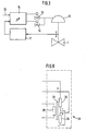
- the system according to FIG. 1 consists of a valve 1, a heat exchanger 2 as a consumption resistor and a pump 3 which effects the flow circuit of the medium in the system.
- the valve 1 is connected to a positioner 6, which in turn is preceded by a microprocessor or process controller 5 for its control.
- Pressure sensors 7 and 8 are arranged upstream and downstream of the valve 1 in order to determine the pressures p 1 and p 2 .
- the temperature T is to be regulated in a container 4. This is recorded by the process computer 5, there: compared with a target value Ts and the control signal w for the valve 1 is determined. This control signal w is fed to the positioner 6 of the valve 1 , which is equipped with a microprocessor or computer circuit (FIG. 3).
- the positioner 6 includes a stroke sensor according to FIG. 3 11, a microprocessor-controlled control electronics 14, with a setpoint input 12, in which the control signal w is fed which, as will be described later, by a Process controller 5 is specified.
- the control electronics 14 in turn gives the signals generated by it to the actuators 13, the Control valve drive 15, the valve cone via the spindle 16 30 actuated.
- the control electronics also have 14 more Inputs for the stroke sensor 11 and possibly also for other sensors.
- the operating characteristic Q (h) can be measured using the pressure measurements p 1 and p 2 of sensors 7 and 8 the microprocessor or computer circuit of the positioner 6 can be calculated.
- Fig. 2 shows a similar system as in Fig. 1, only with the difference that a steam boiler 9 is installed instead of the pump 3 is.
- the temperature T corresponding to the Temperature specification Ts can be regulated.
- To determine the operating characteristic Q (h) is in the circuit of the pipeline 10 a flow meter 17 is arranged.
- the operating characteristic Q (h) of such a system is non-linear.
- the nonlinear operating characteristic Q (h) of the system is therefore determined and converted into a linear function Q ( w ) (FIG. 5).
- a mechanical or electronic transmission element that acts in a specifically non-linear manner can be connected to the positioner 6.
- This can be, for example, a correspondingly designed cam disc, the radii of which are designed in such a way that a linearity Q ( w ) arises.
- the simplest way to obtain the operating characteristic curve Q (h) is by measuring the flow Q as a function of the valve opening h (FIG. 5). However, it can also be done in such a way that the inlet pressure p 1 before the valve 1 and the outlet pressure p 2 immediately after the valve 1 are measured as a function of the valve opening h and taking into account the values from the characteristic curve K v (h) of the valve 1 the operating characteristic Q (h) of the system is determined by calculation.
- pressure sensors 7 and 8 are integrated in valve 1. Through the connection the pressure sensors 7 and 8 directly with the control electronics 14 experiences the valve 1 and thus the system Self control.
- the pressures determined are as above mentioned, directly in the computer of the control electronics 14 for further processing directed.
- valve 4 is a structural design of the valve 1 in Connection to actuator 15 and positioner 6 shown.
- the valve cone 30 of the valve 1 is over the spindle 16 connected to the valve drive 15, which comes from the drive piston 161 and the return spring 18 consists essentially.
- the drive piston 161 is used to adjust the valve cone 30 applied via an air connection opening 29 and an air chamber 28.
- This actuator 15 is directly on the valve 1 centered on the valve spindle 16.
- the positioner 6 is connected by a control line 36 its outlet opening 37 with the air connection opening 29 of the Actuator 15 connected.
- About the actuators 13 Air supply in the air chamber 28 for the actuator 15 of the Valve 1 controlled.
- the positioner 6 is also on this actuator 15 centered on the valve spindle 16. This results in a very compact and simple design without additional transmission parts, that lead to inaccuracies.
- the between Valve actuator 15 and positioner 6 arranged sight glass 31 with the pointer 32 arranged on the valve spindle 16 a reading of the valve position.
- the valve stem 16 continues into positioner 6 and contributes a stroke sensor 11 at its upper end.
- electronic boards 19 are arranged, which also include the microprocessor 14 of the positioner 6 included.
- the stroke sensor 11 can be designed in various ways.
- the stroke sensor 11 is preferably a magnetic-inductive one System executed and works without contact. This results in a particularly reliable design because, on the one hand no moving parts, e.g. Lever and the like accessible from the outside secondly, the stroke detection is wear-free and insensitive to vibrations. This is a requirement for precise and exact control and regulation of the valve opening H.
- FIG. 8 shows the construction and the functional principle in a circuit diagram of the magnetic-inductive stroke sensor 11.
- Die Extension of the valve spindle 16 carries one at its end Ferrite core 20, which in a coil 33 corresponding to the stroke h of the valve cone 30 is moved up and down. Corresponding its position within the coil 33 becomes a corresponding one Current or voltage generated inductively as a measure of the valve opening H.
- a special feature of the stroke sensor 11 is that that the coil 33 has a primary winding 25 and two secondary windings 26, the two secondary windings 26 being coaxial arranged in series, but connected to each other.
- Fig. 9 shows another embodiment of such a contactless working stroke sensor.
- the stroke sensor 111 works an optical principle.
- a cover panel 23 is placed at the end of the extended valve stem 16, instead of the ferrite core 20, a cover panel 23 is placed. This cover 23 is tapered so an exactly right-angled adjustment to the beam path of the light is unnecessary.
- a slit diaphragm 24 is arranged in front of a photocell 22, which through the cover panel 23 corresponding to the lifting movement h the valve stem 16 covered and so that from the photodiode 21 emerging light for the photocell 22 more or less is released.
- This is analogous to the incidence of light and thus the position of the cover panel 23 is a photoelectric Generates current or voltage, which is also a measure of the valve opening h serves.
- the cover 23 can also linearize the Function I (h) can be achieved.
- a particularly expedient version of the stroke sensor 111 exists in a modification of the photocell 22 such that the light rays passing through the slit diaphragm 24 instead of a photocell from a very large number of the smallest individual photo elements - so-called photo bits - that are captured digitally give directly usable signals depending on how many through the position of the cover plate 23 by the photodiode 21st emitted light rays are exposed. These signals can without having to prepare them through digitization, fed directly to the microprocessor 14 for processing become.
- This type of photoelectric scanning also has the advantage that the measurements are independent of the constant maintenance the light intensity are.
- the non-contact stroke sensors described can both with advantage when using the initially described Method for linearizing the operating characteristic Q (h) can also be used independently.
- the described working on inductive as well as optical principles Stroke sensors help linearize the controlled variables when used alone, only for the area of the stroke sensors.
- FIG 10 is the connection of an electrical transmission element 35 to the positioner 6 shown. That from the process controller 5 coming control signal w passes through in this case only the electrical transmission element 35 before it Input 12 of control electronics 14 of positioner 6 reached. Through the connected transmission element 35 the programmed function h (w) is superimposed on the position signal w, so that the linear function Q (w) arises, which then, as already described above, formed by the control electronics 14.
- the mechanical transmission element 34 When using a mechanical non-linear transmission element 34 this is convenient between the valve drive 15 and the stroke sensor 11 of the positioner switched on, the mechanical transmission element 34 each is programmed so that the return to the stroke sensor 11 Valve opening h such a value is added that a linear Function Q (w) arises.
- the nonlinear mechanical Transmission element 34 can be used both as a cam, the Radii are formed in such a way that a linearity Q (w) arises, or as a correspondingly non-linear potentiometer be trained.
Landscapes
- Engineering & Computer Science (AREA)
- Physics & Mathematics (AREA)
- General Engineering & Computer Science (AREA)
- Analytical Chemistry (AREA)
- Fluid Mechanics (AREA)
- Mechanical Engineering (AREA)
- Chemical & Material Sciences (AREA)
- General Physics & Mathematics (AREA)
- Automation & Control Theory (AREA)
- Flow Control (AREA)
- Indication Of The Valve Opening Or Closing Status (AREA)
- Control Of Fluid Pressure (AREA)
- Stabilization Of Oscillater, Synchronisation, Frequency Synthesizers (AREA)
- Feedback Control In General (AREA)
- Servomotors (AREA)
Description
- Fig. 1
- die Anwendung der Erfindung bei einer mit einem flüssigen Medium betriebenen Anlage in schematischer Darstellung;
- Fig.2
- die Anwendung der Erfindung bei einer mit: einem gasförmigen Medium betriebenen Anlage;
- Fig.3
- Schaltbild des Stellungsreglers;
- Fig.4
- eine erfindungsgemäße Ausführung eines Ventils mit Stellantrieb.
- Fig.5 bis 7
- die verschiedenen Meßfunktionen und Kennlinien der Anlage;
- Fig.8
- das Prinzipschaltbild eines induktiv arbeitenden Hubsensors gemäß der Erfindung;
- Fig.9
- den Stellungsregler mit einer anderen Ausführung eines berührungslos arbeitenden Hubsensors;
- Fig. 10 und 11
- den Stellungsregler gem. Fig. 3, jedoch mit zugeschal tetem nichtlinearen mechanischen oder elektrischen Übertragungselement.
oder
oder
- 1
- Ventil
- 2
- Verbrauchswiderstand, Wärmetauscher
- 3
- Pumpe
- 4
- Behälter
- 5
- Prozeßregler/-rechner (reducer)
- 6
- Stellungsregler
- 7, 8
- Drucksensoren
- 9
- Dampfkessel
- 10
- Rohrleitung
- 11, 111
- Hubsensor
- 12
- Sollwert-Eingang
- 13
- Aktoren für Ventilantrieb
- 14
- Regelelektronik mikroprozessorgesteuert
- 15
- Ventilantrieb
- 16
- Ventilspindel
- 161
- Antriebskolben
- 17
- Durchflußsensor
- 18
- Rückstellfeder
- 19
- Regelelektronik, Leiterplatte
- 20
- Ferrit-Kern
- 21
- Lichtquelle, Fotodiode
- 22
- Fotozelle
- 23
- Abdeckblende
- 24
- Schlitzblende
- 25
- Primärwicklung
- 26
- Sekundärwicklung
- 28
- Luftkammer
- 29
- Luftanschlußöffnung
- 30
- Ventilkegel
- 31
- Schauglas
- 32
- Anzeiger
- 33
- Spule
- 34
- Mechanisches Übertragungselement
- 35
- Elektrisches Übertragungselement
- 36
- Steuerleitung
- 37
- Ausgangsöffnung
- h
- Ventilöffnung, Hub
- w
- Stellsignal
- Q
- Durchflußmenge
Claims (26)
- Verfahren zur Steuerung der Öffnung h eines in einer Anlage integrierten Ventiles mittels eines Stellungsreglers, dem ein Stellsignal w zugeführt wird, auf eine gewünschte Durchflußmenge Q, dadurch gekennzeichnet, daß die nichtlineare Betriebskennlinie Q(h) der Anlage durch Bestimmung der Durchflußmenge Q in Abhängigkeit der Ventilöffnung h ermittelt und zu den jeweiligen Ventilöffnungen h die zugehörige Stellsignal w ermittelt wird, so daß sich eine Funktion w(h) ergibt, die so erhaltene Funktion w(h) der Funktion Q(h) überlagert wird, so daß die Werte Q(w) auf einer Geraden liegen, wobei die auf einer Geraden liegenden Werte des Stellsignales w zur Steuerung des Ventiles für eine gewünschte Durchflußmenge Q eingesetzt werden.
- Verfahren nach Anspruch 1, dadurch gekennzeichnet, daß die Bestimmung der Durchflußmenge Q durch direkte Messung in der Anlage als Funktion der Ventilöffnung h bestimmt wird.
- Verfahren nach Anspruch 1, dadurch gekennzeichnet, daß die Bestimmung der Durchflußmenge Q durch Messen des Eingangsdruckes (p1) vor dem Ventil und des Ausgangsdruckes (p2) unmittelbar nach dem Ventil als Funktion der zugehörigen Ventilöffnung h gemessen und unter Einbeziehung der Werte aus der Kennlinie Kv(h) des Ventils (1) einem Rechner zugeleitet werden, welcher die Funktion h(w) aus den Meßwerten (p1, p2; Q) ermittelt und auf einen Mikroprozessor (14) des Stellungsreglers (6) überträgt.
- Verfahren nach Anspruch 3, dadurch gekennzeichnet, daß die gemessenen Werte (p1 und p2; Q) einem Rechner zur Verarbeitung zugeleitet werden, welcher die Funktion h(w) aus den Meßwerten (p1, p2; Q) ermittelt und auf den Mikroprozessor (14) des Stellungsreglers (6) überträgt.
- Vorrichtung zur Steuerung der Öffnung h eines in eine Anlage integrierten Ventiles (1), wobei die Anlage einen Verbrauchswiderstand (2) und die Durchströmung der Anlage bewirkende Mittel (3; 9) aufweist, und das Ventil (1) über einen Stellungsregler (6) betätigt wird, der einen Sensor (11; 111) zur Erfassung der aktuellen Ventilöffnung h, einen Sollwerteingang (12) für ein Stellsignal w sowie Aktoren (13) zur Ansteuerung des Ventilantriebes (15) und eine Mikroprozessorschaltung aufweist, dadurch gekennzeichnet, daß Mittel (7, 8; 17) zur Feststellung der Menge Q des die Anlage durchströmenden Mediums in Abhängigkeit zur Ventilöffnung h vorgesehen sind und der Stellungsregler (6) mit einer Regelelektronik (14) ausgerüstet ist, die diese werte Q(h) einem vorgegebenen Stellsignal w jeweils zuordnet, wobei das Stellsignal w für die Steuerung des Ventils (1) in eine solche Ventilöffnung h umgewandelt wird, daß eine lineare Funktion Q(w) entsteht.
- Vorrichtung nach Anspruch 5, dadurch gekennzeichnet, daß vor und nach dem Ventil (1) Drucksensoren (7, 8) angeordnet sind.
- Vorrichtung nach Anspruch 6, dadurch gekennzeichnet, daß die Drucksensoren (7, 8) in das Ventil (1) integriert sind.
- Vorrichtung nach einem der Ansprüche 5 oder 6, dadurch gekennzeichnet, daß die Regelelektronik (14) des Stellungsreglers (6) mit den Drucksensoren (7, 8) verbunden ist und die für die Steuerung des Ventils (1) gemessenen Drücke (p1, p2) zur Ermittlung der Betriebskennlinie Q(h) der Anlage auswertet.
- Vorrichtung nach Anspruch 5, dadurch gekennzeichnet, daß für das die Anlage durchströmende Medium eine Rohrleitung (10) vorgesehen ist, in welcher ein Durchflußmesser (17) angeordnet ist.
- Vorrichtung nach Anspruch 5, dadurch gekennzeichnet, daß in das Ventil (1) ein Durchflußmesser (17) integriert ist.
- Vorrichtung nach einem oder mehreren der Ansprüche 5 bis 10, dadurch gekennzeichnet, daß dem Stellungsregler (6) ein gezielt nichtlinear wirkendes mechanisches oder elektronisches Übertragungselement (34; 35) zugeschaltet ist, das derart ausgebildet ist, daß das dem Stellungsregler (6) zugeführte Stellsignal w in eine solche Ventilöffnung h umgewandelt wird, daß eine lineare Funktion Q(w) entsteht.
- Vorrichtung nach Anspruch 11, dadurch gekennzeichnet, daß das mechanische Übertragungselement (34) zwischen dem Ventilantrieb (15) und einem die Ventilöffnung h anzeigenden Hubsensor (11) zugeschaltet ist.
- Vorrichtung nach einem der Ansprüche 11 oder 12, dadurch gekennzeichnet, daß das mechanische Übertragungselement (34) als Kurvenscheibe ausgebildet ist, deren Radien derart gestaltet sind, daß eine Linearität Q(W) entsteht.
- Vorrichtung nach Anspruch 11, dadurch gekennzeichnet, daß das elektrische Übertragungselement (35) der Regelelektronik (14) des Stellungsreglers (6) vorgeschaltet und derart programmiert ist, daß eine Linearität Q(w) entsteht.
- Vorrichtung nach einem oder mehreren der Ansprüche 5 bis 14, dadurch gekennzeichnet, daß das Ventil (1) einen auf eine Ventilspindel (16) einwirkenden Ventilantrieb (15) aufweist, in dessen axialer Verlängerung der Stellungsregler (6) zentrisch zur Ventilspindel (16) angeordnet ist.
- Vorrichtung nach einem oder mehreren der Ansprüche 5 bis 15, dadurch gekennzeichnet, daß der Stellungsregler (6) einen berühruhgslos arbeitenden Hubsensor (11; 111) aufweist, durch den die ventilöffnung h erfaßt wird.
- Vorrichtung nach Anspruch 16, dadurch gekennzeichnet, daß der Hubsensor (11) magnetisch-induktiv arbeitet.
- Vorrichtung nach Anspruch 17, dadurch gekennzeichnet, daß der Hubsensor (11) eine Spule (33) aufweist, in welcher ein Ferritkern (20) entsprechend der Stellbewegung für die Ventilöffnung h eintaucht, die eine Primärwicklung (25) und zwei Sekundärwicklungen (26) beinhaltet, wobei die beiden Sekundärwicklungen (26) koaxial in Reihe angeordnet sind.
- Vorrichtung nach Anspruch 18, dadurch gekennzeichnet, daß der Ferritkern (20) entsprechend der Stellbewegung für die Ventilöffnung h innerhalb der Spule (33) positioniert ist.
- Vorrichtung nach einem der Ansprüche 18 oder 19, dadurch gekennzeichnet, daß die beiden Sekundärspulen (26) gegeneinander geschaltet sind, sodaß sich bei symmetrischer Lage des Ferritkernes (20) zu den beiden Sekundärwicklungen (26) die Induktion aufhebt.
- Vorrichtung nach Anspruch 16, dadurch gekennzeichnet, daß der Hubsensor (111) eine Fotodiode (21), eine mit der Ventilspindel (16) gekoppelte bewegliche Abdeckblende (23) sowie Mittel zur Aufnahme der von der Fotodiode (21) ausgesandten Lichtstrahlen aufweist.
- Vorrichtung nach Anspruch 21, dadurch gekennzeichnet, daß die Abdeckblende (23) am Ende der verlängerten Ventilspindel (16) angeordnet ist und mit einer Schlitzblende (24) zusammenarbeitet.
- Vorrichtung nach einem der Ansprüche 21 oder 22, dadurch gekennzeichnet, daß die Abdeckblende (23) rotationssymmetrisch ausgebildet ist.
- Vorrichtung nach einem oder mehreren der Ansprüche 21 bis 23, dadurch gekennzeichnet, daß die Abdeckblende (23) so in ihrer Mantellinie gestaltet ist, daß eine Linearisierung des durch die Stellung der Abdeckblende 23 erzeugten Stromes I in Abhängigkeit der Ventilöffnung h [Funktion I(h)] erfolgt.
- Vorrichtung nach einem oder mehreren der Ansprüche 21 bis 24, dadurch gekennzeichnet, daß anstatt einer die Lichtstrahlen der Fotodiode (21) auffangenden Fotozelle (22) diese in eine sehr große Anzahl von kleinsten Einzel-Fotoelementen (Fotobits) aufgeteilt ist, welche digital direktverwertbare Signale abgeben.
- Vorrichtung nach Anspruch 25, dadurch gekennzeichnet, daß die Fotobits an den Mikroprozessor (14) des Stellungsreglers (6) angeschlossen sind.
Applications Claiming Priority (2)
| Application Number | Priority Date | Filing Date | Title |
|---|---|---|---|
| DE19540441 | 1995-10-27 | ||
| DE19540441A DE19540441A1 (de) | 1995-10-27 | 1995-10-27 | Mikroprozessorgesteuerter Stellungsregler |
Publications (2)
| Publication Number | Publication Date |
|---|---|
| EP0782060A1 EP0782060A1 (de) | 1997-07-02 |
| EP0782060B1 true EP0782060B1 (de) | 2002-04-10 |
Family
ID=7776197
Family Applications (1)
| Application Number | Title | Priority Date | Filing Date |
|---|---|---|---|
| EP96117147A Expired - Lifetime EP0782060B1 (de) | 1995-10-27 | 1996-10-25 | Mikroprozessorgesteuerter Stellungsregler |
Country Status (5)
| Country | Link |
|---|---|
| US (1) | US5878765A (de) |
| EP (1) | EP0782060B1 (de) |
| AT (1) | ATE216094T1 (de) |
| DE (2) | DE19540441A1 (de) |
| ES (1) | ES2172614T3 (de) |
Cited By (1)
| Publication number | Priority date | Publication date | Assignee | Title |
|---|---|---|---|---|
| DE102014117988A1 (de) * | 2014-12-05 | 2016-06-09 | Pierburg Gmbh | Verfahren zur Kalibrierung eines Regelventils |
Families Citing this family (28)
| Publication number | Priority date | Publication date | Assignee | Title |
|---|---|---|---|---|
| EP0884481A3 (de) * | 1997-06-09 | 2000-09-27 | Bürkert Werke GmbH & Co. | Pneumatischer Stellungsregler |
| US6272401B1 (en) | 1997-07-23 | 2001-08-07 | Dresser Industries, Inc. | Valve positioner system |
| EP1445676B1 (de) * | 1997-07-23 | 2008-05-21 | Dresser, Inc. | Ventilpositionierungssystem |
| US6192321B1 (en) * | 1997-09-29 | 2001-02-20 | Fisher Controls International, Inc. | Method of and apparatus for deterministically obtaining measurements |
| AUPP512398A0 (en) * | 1998-08-07 | 1998-09-03 | Resmed Limited | A control member for a valve and method for determining fluid flow rate through a valve |
| DE19960190A1 (de) * | 1999-12-14 | 2001-07-05 | Bosch Gmbh Robert | Regelventil |
| ES2180398B1 (es) * | 2000-12-11 | 2004-03-01 | Almela Jesus Martinez | Sistema para el control del caudal a traves de una conduccion. |
| AU2002307547A1 (en) * | 2001-04-24 | 2002-11-05 | Unit Instruments, Inc. | System and method for configuring and asapting a mass flow controller |
| EP1457856B1 (de) * | 2001-04-24 | 2005-11-23 | Celerity Group, Inc. | Verfahren zur Bestimmung einer Ventilöffnung für einen Massenflussregler |
| US6830061B2 (en) * | 2001-04-27 | 2004-12-14 | Fisher Controls International Llc | Intelligent regulator with input/output capabilities |
| US6745770B2 (en) * | 2002-01-08 | 2004-06-08 | Resmed Limited | Flow diverter for controlling the pressure and flow rate in a CPAP device |
| KR20050031109A (ko) * | 2002-07-19 | 2005-04-01 | 셀레리티 그룹 아이엔씨 | 질량 유량 제어기 내의 압력 보상을 위한 방법 및 장치 |
| AU2003284128A1 (en) * | 2002-10-11 | 2004-05-04 | Saudi Arabian Oil Company | Automatic valve characterization of digital valve positioners |
| DE602004012980T2 (de) * | 2003-02-14 | 2009-05-07 | Dresser, Inc., Addison | Verfahren, system und speichermedium zur durchführung von online-ventildiagnose |
| US7216019B2 (en) * | 2004-07-08 | 2007-05-08 | Celerity, Inc. | Method and system for a mass flow controller with reduced pressure sensitivity |
| JP4639813B2 (ja) * | 2005-01-20 | 2011-02-23 | トヨタ自動車株式会社 | 液圧制御装置および作動特性取得装置 |
| DE102005049061B3 (de) * | 2005-10-13 | 2007-03-29 | Samson Ag | Vorrichtung und Verfahren zur Stellungsregelung eines pneumatischen Stellgeräts |
| US7283894B2 (en) | 2006-02-10 | 2007-10-16 | Dresser, Inc. | System and method for fluid regulation |
| DE102006045976B4 (de) * | 2006-09-27 | 2013-01-31 | Krohne Ag | Durchflussmessgerät |
| US7539560B2 (en) | 2007-01-05 | 2009-05-26 | Dresser, Inc. | Control valve and positioner diagnostics |
| JP2009115271A (ja) * | 2007-11-09 | 2009-05-28 | Yamatake Corp | 流量計測バルブ |
| DK3812870T4 (da) | 2008-06-26 | 2026-03-23 | Belparts Group N V | Flødstyresystem |
| DE102010007152B4 (de) * | 2010-02-05 | 2017-03-30 | Hoerbiger Automatisierungstechnik Holding Gmbh | Fluidbetätigter Stellantrieb an einer Armatur |
| DE102012021388B4 (de) * | 2012-10-31 | 2022-02-03 | Samson Aktiengesellschaft | Pneumatisches Antriebssystem und Verfahren zum Betreiben des pneumatischen Antriebssystems |
| DE102013007927B4 (de) | 2013-05-10 | 2014-12-24 | Hoerbiger Automatisierungstechnik Holding Gmbh | Antriebseinheit |
| EP2829379A1 (de) * | 2013-07-22 | 2015-01-28 | Eugen Seitz AG | Ventilanordnung |
| DE102015005832B3 (de) * | 2015-05-07 | 2016-11-03 | Samson Aktiengesellschaft | Feldgerät zum Regeln eines Prozessfluidstroms |
| DE102017210026B3 (de) | 2017-06-14 | 2018-08-30 | Festo Ag & Co. Kg | Verfahren zum Ermitteln einer arbeitspunktabhängigen Reglerverstärkungskennlinie und Regeleinrichtung zur Ansteuerung einer Stelleinrichtung |
Citations (1)
| Publication number | Priority date | Publication date | Assignee | Title |
|---|---|---|---|---|
| DE2916172A1 (de) * | 1979-04-21 | 1980-10-23 | Karl Hehl | Proportionalventil fuer hydraulische anlagen |
Family Cites Families (15)
| Publication number | Priority date | Publication date | Assignee | Title |
|---|---|---|---|---|
| US3552428A (en) * | 1968-06-20 | 1971-01-05 | Phillips Petroleum Co | Automatically tuned process controller |
| DE3642642C3 (de) * | 1986-12-13 | 1994-09-01 | Rexroth Mannesmann Gmbh | Schaltungsanordnung zur Lage- und Vorschubregelung eines hydraulischen Antriebes |
| FI79407C (fi) * | 1987-06-18 | 1989-12-11 | Halton Oy | Foerfarande och anordning foer reglering av volymstroemmen i ventilationsanlaeggningar. |
| DE3909693A1 (de) * | 1988-05-26 | 1989-11-30 | Rexroth Mannesmann Gmbh | Elektrisch verstellbares ventil, insbesondere drosselventil |
| US4813443A (en) * | 1988-04-06 | 1989-03-21 | Signet Scientific Company | Method for controllably positioning a solenoid plunger |
| DE3838353A1 (de) * | 1988-11-11 | 1990-05-17 | Rexroth Mannesmann Gmbh | Elektrischer verstaerker zum ansteuern von ventilen |
| DE3911259C2 (de) * | 1989-04-07 | 1994-03-17 | Rexroth Mannesmann Gmbh | Ansteuerelektronik für ein elektrisch verstellbares Regelventil |
| DE3931962A1 (de) * | 1989-09-25 | 1991-04-04 | Rexroth Mannesmann Gmbh | Ansteuerelektronik fuer ein elektrisch verstellbares stellglied |
| US5190068A (en) * | 1992-07-02 | 1993-03-02 | Brian Philbin | Control apparatus and method for controlling fluid flows and pressures |
| DE4415054C1 (de) * | 1993-05-11 | 1995-05-24 | Rexroth Mannesmann Gmbh | Steuerung für einen hydraulischen Antrieb (simulierte Zustandsgrößen) |
| DE4315626C1 (de) * | 1993-05-11 | 1994-07-14 | Rexroth Mannesmann Gmbh | Steuerung für einen hydraulischen Antrieb |
| US5549137A (en) * | 1993-08-25 | 1996-08-27 | Rosemount Inc. | Valve positioner with pressure feedback, dynamic correction and diagnostics |
| US5537388A (en) * | 1994-03-02 | 1996-07-16 | The Foxboro Company | Method and apparatus for characterizing and compensating for non-linear components |
| DE4417153C1 (de) * | 1994-05-17 | 1995-11-16 | Siemens Ag | Schaltungsanordnung und Verfahren zum Regeln der Lage eines ventilgesteuerten hydraulischen Stellglieds |
| DE4431463C2 (de) * | 1994-09-03 | 1997-10-16 | Honeywell Ag | Kompaktregler für ein Regelventil |
-
1995
- 1995-10-27 DE DE19540441A patent/DE19540441A1/de not_active Withdrawn
-
1996
- 1996-10-25 EP EP96117147A patent/EP0782060B1/de not_active Expired - Lifetime
- 1996-10-25 ES ES96117147T patent/ES2172614T3/es not_active Expired - Lifetime
- 1996-10-25 DE DE59609055T patent/DE59609055D1/de not_active Expired - Lifetime
- 1996-10-25 AT AT96117147T patent/ATE216094T1/de not_active IP Right Cessation
- 1996-10-25 US US08/739,100 patent/US5878765A/en not_active Expired - Fee Related
Patent Citations (1)
| Publication number | Priority date | Publication date | Assignee | Title |
|---|---|---|---|---|
| DE2916172A1 (de) * | 1979-04-21 | 1980-10-23 | Karl Hehl | Proportionalventil fuer hydraulische anlagen |
Cited By (1)
| Publication number | Priority date | Publication date | Assignee | Title |
|---|---|---|---|---|
| DE102014117988A1 (de) * | 2014-12-05 | 2016-06-09 | Pierburg Gmbh | Verfahren zur Kalibrierung eines Regelventils |
Also Published As
| Publication number | Publication date |
|---|---|
| DE19540441A1 (de) | 1997-04-30 |
| ES2172614T3 (es) | 2002-10-01 |
| US5878765A (en) | 1999-03-09 |
| ATE216094T1 (de) | 2002-04-15 |
| EP0782060A1 (de) | 1997-07-02 |
| DE59609055D1 (de) | 2002-05-16 |
Similar Documents
| Publication | Publication Date | Title |
|---|---|---|
| EP0782060B1 (de) | Mikroprozessorgesteuerter Stellungsregler | |
| CA1142411A (en) | Proportional valve for hydraulic systems | |
| EP0286722B1 (de) | Elektropneumatischer Stellungsregler | |
| DE2102197C3 (de) | Drucksteuereinrichtung | |
| DE2757297A1 (de) | Detektoranordnung zur messung einer bewegung | |
| EP0067298B1 (de) | Elektrisch betätigter Hubmagnet mit Hublageerkennung | |
| DE4431463C2 (de) | Kompaktregler für ein Regelventil | |
| DE10214734A1 (de) | Magnetflussdetektor | |
| DE69416813T2 (de) | Interferenzspektrometer | |
| DE3220815C2 (de) | Druckregelvorrichtung für gasförmige und flüssige Strömungsmittel | |
| DE3345880A1 (de) | Direktwirkendes steuerventil | |
| DE3730940A1 (de) | Vorrichtung zur anzeige der stellung des kolbens eines ventils | |
| DE4108080C2 (de) | Druckregelventil | |
| DE102008028189A1 (de) | Elektropneumatisches Ventil | |
| DE1244922B (de) | Elektrischer Regler mit einer photoelektrischen Abtasteinrichtung | |
| DE2042754C3 (de) | Fluidmeßeinrichtung | |
| DD159362A1 (de) | Anordnung zur gerad-und ebenheitsmessung | |
| DE2326395A1 (de) | Regelung der zufuhr eines ersten fluidums und eines zweiten fluidums an einem ofen, insbesondere industrieofen und waermeerzeuger | |
| EP0016866B1 (de) | Einrichtung zum Unwirksammachen von durch Temperaturschwankungen verursachten Abweichungen der Ausgangsspannung eines Druckwandlers in Magnetbandgeräten | |
| DE19501766A1 (de) | Verfahren und Vorrichtung zur Ansteuerung eines elektromagnetischen Verbrauchers | |
| EP1211487B1 (de) | Vorrichtung für die Messung und Regelung der Verbrauchswerte von Energieträgerflüssigkeiten | |
| DE19508954C1 (de) | Anordnung zum Einstellen der Absperrstellung eines gegen mindestens eine Feder arbeitenden Proportionalventils, insbesondere Wegeventils | |
| DE2416235A1 (de) | Drucksteuerventil | |
| DE102005040536A1 (de) | Verfahren und Vorrichtung zum Messen einer Kraft und einer Position | |
| DE19937597A1 (de) | Druckmittelbetriebener Stellantrieb |
Legal Events
| Date | Code | Title | Description |
|---|---|---|---|
| PUAI | Public reference made under article 153(3) epc to a published international application that has entered the european phase |
Free format text: ORIGINAL CODE: 0009012 |
|
| AK | Designated contracting states |
Kind code of ref document: A1 Designated state(s): AT CH DE ES FR GB IT LI |
|
| 17P | Request for examination filed |
Effective date: 19971113 |
|
| 17Q | First examination report despatched |
Effective date: 19991019 |
|
| GRAG | Despatch of communication of intention to grant |
Free format text: ORIGINAL CODE: EPIDOS AGRA |
|
| GRAG | Despatch of communication of intention to grant |
Free format text: ORIGINAL CODE: EPIDOS AGRA |
|
| GRAH | Despatch of communication of intention to grant a patent |
Free format text: ORIGINAL CODE: EPIDOS IGRA |
|
| REG | Reference to a national code |
Ref country code: GB Ref legal event code: IF02 |
|
| GRAH | Despatch of communication of intention to grant a patent |
Free format text: ORIGINAL CODE: EPIDOS IGRA |
|
| GRAA | (expected) grant |
Free format text: ORIGINAL CODE: 0009210 |
|
| AK | Designated contracting states |
Kind code of ref document: B1 Designated state(s): AT CH DE ES FR GB IT LI |
|
| REF | Corresponds to: |
Ref document number: 216094 Country of ref document: AT Date of ref document: 20020415 Kind code of ref document: T |
|
| REG | Reference to a national code |
Ref country code: CH Ref legal event code: EP |
|
| GBT | Gb: translation of ep patent filed (gb section 77(6)(a)/1977) |
Effective date: 20020411 |
|
| REF | Corresponds to: |
Ref document number: 59609055 Country of ref document: DE Date of ref document: 20020516 |
|
| ET | Fr: translation filed | ||
| REG | Reference to a national code |
Ref country code: ES Ref legal event code: FG2A Ref document number: 2172614 Country of ref document: ES Kind code of ref document: T3 |
|
| PLBE | No opposition filed within time limit |
Free format text: ORIGINAL CODE: 0009261 |
|
| STAA | Information on the status of an ep patent application or granted ep patent |
Free format text: STATUS: NO OPPOSITION FILED WITHIN TIME LIMIT |
|
| 26N | No opposition filed |
Effective date: 20030113 |
|
| PGFP | Annual fee paid to national office [announced via postgrant information from national office to epo] |
Ref country code: CH Payment date: 20081027 Year of fee payment: 13 |
|
| PGFP | Annual fee paid to national office [announced via postgrant information from national office to epo] |
Ref country code: ES Payment date: 20081015 Year of fee payment: 13 Ref country code: AT Payment date: 20081028 Year of fee payment: 13 |
|
| PGFP | Annual fee paid to national office [announced via postgrant information from national office to epo] |
Ref country code: IT Payment date: 20081022 Year of fee payment: 13 |
|
| PGFP | Annual fee paid to national office [announced via postgrant information from national office to epo] |
Ref country code: FR Payment date: 20081024 Year of fee payment: 13 |
|
| PGFP | Annual fee paid to national office [announced via postgrant information from national office to epo] |
Ref country code: GB Payment date: 20081028 Year of fee payment: 13 |
|
| REG | Reference to a national code |
Ref country code: CH Ref legal event code: PL |
|
| REG | Reference to a national code |
Ref country code: FR Ref legal event code: ST Effective date: 20100630 |
|
| PG25 | Lapsed in a contracting state [announced via postgrant information from national office to epo] |
Ref country code: FR Free format text: LAPSE BECAUSE OF NON-PAYMENT OF DUE FEES Effective date: 20091102 |
|
| PG25 | Lapsed in a contracting state [announced via postgrant information from national office to epo] |
Ref country code: AT Free format text: LAPSE BECAUSE OF NON-PAYMENT OF DUE FEES Effective date: 20091025 |
|
| PG25 | Lapsed in a contracting state [announced via postgrant information from national office to epo] |
Ref country code: LI Free format text: LAPSE BECAUSE OF NON-PAYMENT OF DUE FEES Effective date: 20091031 Ref country code: CH Free format text: LAPSE BECAUSE OF NON-PAYMENT OF DUE FEES Effective date: 20091031 |
|
| PG25 | Lapsed in a contracting state [announced via postgrant information from national office to epo] |
Ref country code: GB Free format text: LAPSE BECAUSE OF NON-PAYMENT OF DUE FEES Effective date: 20091025 |
|
| REG | Reference to a national code |
Ref country code: ES Ref legal event code: FD2A Effective date: 20110330 |
|
| PG25 | Lapsed in a contracting state [announced via postgrant information from national office to epo] |
Ref country code: IT Free format text: LAPSE BECAUSE OF NON-PAYMENT OF DUE FEES Effective date: 20091025 |
|
| PG25 | Lapsed in a contracting state [announced via postgrant information from national office to epo] |
Ref country code: ES Free format text: LAPSE BECAUSE OF NON-PAYMENT OF DUE FEES Effective date: 20110317 |
|
| PG25 | Lapsed in a contracting state [announced via postgrant information from national office to epo] |
Ref country code: ES Free format text: LAPSE BECAUSE OF NON-PAYMENT OF DUE FEES Effective date: 20091026 |
|
| PGFP | Annual fee paid to national office [announced via postgrant information from national office to epo] |
Ref country code: DE Payment date: 20151027 Year of fee payment: 20 |
|
| REG | Reference to a national code |
Ref country code: DE Ref legal event code: R071 Ref document number: 59609055 Country of ref document: DE |