EP0782242A1 - Elektromechanischer Wandler mit mehreren Rotoren und Steuerverfahren dafür - Google Patents
Elektromechanischer Wandler mit mehreren Rotoren und Steuerverfahren dafür Download PDFInfo
- Publication number
- EP0782242A1 EP0782242A1 EP96120327A EP96120327A EP0782242A1 EP 0782242 A1 EP0782242 A1 EP 0782242A1 EP 96120327 A EP96120327 A EP 96120327A EP 96120327 A EP96120327 A EP 96120327A EP 0782242 A1 EP0782242 A1 EP 0782242A1
- Authority
- EP
- European Patent Office
- Prior art keywords
- rank
- coil
- rotor
- transverse
- stator
- Prior art date
- Legal status (The legal status is an assumption and is not a legal conclusion. Google has not performed a legal analysis and makes no representation as to the accuracy of the status listed.)
- Granted
Links
- 238000000034 method Methods 0.000 title claims description 7
- 230000005415 magnetization Effects 0.000 claims description 20
- 238000004804 winding Methods 0.000 abstract 3
- 230000004044 response Effects 0.000 description 13
- 230000000694 effects Effects 0.000 description 9
- 102100040160 Rabankyrin-5 Human genes 0.000 description 4
- 101710086049 Rabankyrin-5 Proteins 0.000 description 4
- 230000003993 interaction Effects 0.000 description 4
- 238000012986 modification Methods 0.000 description 2
- 230000004048 modification Effects 0.000 description 2
- 238000010276 construction Methods 0.000 description 1
- 238000013461 design Methods 0.000 description 1
- 238000011161 development Methods 0.000 description 1
- 238000004519 manufacturing process Methods 0.000 description 1
- 230000035699 permeability Effects 0.000 description 1
- 238000012797 qualification Methods 0.000 description 1
Images


Classifications
-
- H—ELECTRICITY
- H02—GENERATION; CONVERSION OR DISTRIBUTION OF ELECTRIC POWER
- H02K—DYNAMO-ELECTRIC MACHINES
- H02K16/00—Machines with more than one rotor or stator
- H02K16/02—Machines with one stator and two or more rotors
-
- G—PHYSICS
- G04—HOROLOGY
- G04C—ELECTROMECHANICAL CLOCKS OR WATCHES
- G04C3/00—Electromechanical clocks or watches independent of other time-pieces and in which the movement is maintained by electric means
- G04C3/14—Electromechanical clocks or watches independent of other time-pieces and in which the movement is maintained by electric means incorporating a stepping motor
- G04C3/146—Electromechanical clocks or watches independent of other time-pieces and in which the movement is maintained by electric means incorporating a stepping motor incorporating two or more stepping motors or rotors
Definitions
- the present invention relates to an electromechanical transducer comprising a single stator and several rotors which can be used, for example, to drive the various indicators of a timepiece such as the indicators of the current time, of the date, of the day of weekdays, timed time, wake-up time, etc.
- An object of the present invention is to provide such a transducer whose various rotors can be controlled independently of each other and so that they rotate selectively in one or the other of their two directions of rotation while having a compact and relatively inexpensive structure.
- stator poles partially surrounding any of the openings provided for the rotors, are connected directly to the first ends of two transverse parts forming cores respectively surrounded by two coils and a third stator pole also partially surrounding this opening is directly connected to a transverse part which does not carry a coil and which is connected to the second ends of the two transverse parts carrying coils.
- Another object of the present invention is to provide a method for controlling such a transducer so that its various rotors rotate independently of each other, selectively in one or the other of their two directions of rotation.
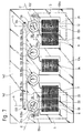
- the electromechanical transducer of the present invention which is designated by the general reference 1, comprises a stator, four rotors and five coils.
- the stator which is designated by the reference 2, has two main parts 3 and 4 each having a first end 3a, 4a, and a second end 3b, 4b.
- the first end of the stator 2 will be called the one where the first ends 3a and 4a of the main parts 3 and 4 are located and the second end of the stator 2 the one where the second ends 3b and 4b of these main parts 3 and 4 are located.
- the stator 2 further comprises nine transverse parts 5 to 13 adjacent to each other and each having a first and a second end which are respectively connected to the first main part 3 and to the second main part 4.
- the first ends 3a and 4a , and the second ends 3b and 4b of these two main parts 3 and 4 are respectively connected by the transverse parts 5 and 13.
- parts 3 and 4 on the one hand, and parts 5 to 13 on the other hand are respectively qualified as main and transverse only to distinguish them from each other and to simplify the present description. .
- each of these parts, whatever their qualification, is just as important and essential to the construction and operation of the transducer 1 as any of the other parts.
- a rank will be assigned to each of the transverse parts 5 to 13, starting arbitrarily with the transverse part 5 which is closest to the first end of the stator 2 and following the order in which these parts transverse are arranged in this stator 2. Row one is thus assigned to the transverse part 5, row two to the transverse part 6, and so on to the transverse part 13 which is closest to the second end of the stator 2 and to which rank nine is assigned.
- the transverse parts of odd rank that is to say those which are designated by the references 5, 7, 9, 11 and 13, and the transverse parts of even rank, ie those which are designated by references 6, 8, 10 and 12.
- the stator 2 is pierced with four openings 14 to 17 which are all formed in the main part 3, each in the extension of one of the transverse parts of even rank 6, 8, 10 and 12.
- the openings 14 to 17 have the general shape of circular cylinders having respectively central axes 14a, 15a, 16a and 17a.
- the transducer 1 further comprises four rotors 18 to 21 which each pass through one of the openings 14 to 17. Each of these rotors 18 to 21 is rotatable around an axis which coincides with that of the opening 14 to 17 that it crosses and which will be designated by the same reference as the latter.
- each of these rotors 18 to 21 comprises a permanent bipolar magnet with radial magnetization which is located in the opening 14 to 17 through which this rotor passes.
- These permanent magnets are the only ones represented in FIG. 1 where they are respectively designated by the references 18a to 21a.
- the magnetization axes of the magnets 18a to 21a which are perpendicular to the respective axes of rotation 14a to 17a, are respectively designated by the references 18b to 21b and are symbolized by arrows in solid lines.
- the transducer 1 also comprises five coils 22 to 26 which each surround one of the transverse parts of odd rank 5, 7, 9, 11 and 13 of the stator 2 and which are connected, by connections not shown, to an electronic circuit of control of the transducer 1, also not shown, the operation of which will be described later.
- transverse parts of even rank 6, 8, 10 and 12 preferably form only one piece with the main parts 3 and 4, and that this piece is made of a material with high permeability.
- magnetic such as one of those commonly used to manufacture the stator of conventional stepper motors.
- transverse parts of odd rank 5, 7, 9, 11 and 13, which respectively constitute the cores of the coils 22 to 26 are preferably parts added to the rest of the stator 2 and magnetically connected to the main parts 3 and 4 by fixing means, such as screws or rivets, not shown.
- stator poles the two portions of the main part 3 and the portion of one of the transverse parts 6, 8, 10 and 12 which surround each of the openings 14 and 17 will be called stator poles, and the ends of these stator poles forming part of the internal wall of these openings 14 to 17 will be called pole shoes.
- the stator poles surrounding the openings 14 to 17 will be respectively designated by the references 27 to 29, 30 to 32, 33 to 35 and 36 to 38, the stator poles 28, 31, 34 and 37 being respectively portions of the transverse parts 6, 8, 10 and 12, and the other stator poles all being portions of the main part 3.
- the pole shoes formed by the ends of the stator poles 27 to 38 will be respectively designated by the references 27a to 38a.
- stator poles which are portions of the main part 3 as well as the pole shoes which terminate them will be qualified as main.
- stator poles which are portions of the transverse parts of even rank as well as the pole shoes which terminate them will be qualified as transverse.
- the dimensions of the main part 3 and the transverse parts of even rank 6, 8, 10 and 12, as well as the relative arrangement of these various parts and the openings 14 to 17 are chosen so that the three stator poles which each surround these openings are separated two by two by areas of sufficiently small section so that their reluctance is much higher than that of the other parts of the stator 2 so as to magnetically isolate said three stator poles.
- Such high reluctance zones are commonly called isthmus.
- these dimensions and this arrangement are chosen so that the two main pole shoes which partially surround each opening 14 to 17 are symmetrical to each other with respect to a plane containing the axis 14a to 17a of this opening and passing through the middle of the transverse polar expansion which also partially surrounds this same opening, and so that this transverse polar expansion is itself symmetrical with respect to this same plane.
- the four planes of symmetry of the openings 14 to 17 are respectively designated by the references A to D, and their traces in the plane of Figure 1 are partially represented by dashed lines.
- each main stator pole is connected directly to a first end of one of the transverse parts which constitute the cores of the coils 22 to 26, that is to say the transverse parts of odd rank in the example of FIG. 1 .
- transverse stator poles are connected directly to a first end of one of the transverse parts which do not carry a coil, that is to say the transverse parts of even rank in the example of FIG. 1.
- the transducer 1 also comprises means for positioning the rotors 18 to 21, which are arranged so that each of these rotors has two rest positions, or minimum energy positions, and that these two positions are those where the axes of magnetization 18b to 21b magnets 18a to 21a are respectively located in the planes of symmetry A, B, C or D defined above.
- each of the rotors 18 to 21 are arranged so that, in the two rest positions of this rotor, the direction of the magnetization axis of its magnet passes through the middle of polar expansion located at the end of the only stator pole which is not directly connected to the core of a coil among the three stator poles surrounding the opening in which this rotor is arranged.
- each of the rotors 18 to 21 are constituted by two notches each formed in one of the main pole shoes which partially surround this rotor, these two notches being moreover symmetrical one of the other with respect to the respective plane of symmetry A, B, C or D.
- the magnets 18a to 21a of the rotors 18 to 21 have all been represented in that of the two rest positions of these rotors where their magnetization axis 18b to 21b is oriented towards the isthmus diametrically opposite to the blooming transverse polar 28a, 31a, 34a or 37a respectively.
- This rest position of the rotors 18 to 21 will be arbitrarily called the first rest position.
- the other rest position of the rotors 18 to 21, that is to say that where the magnetization axis 18b to 21b of their magnet 18a to 21a is oriented towards the middle of the transverse polar expansion 28a, 31a, 34a or 37a respectively, will then obviously be called the second rest position.
- the operation of the transducer 1 will now be described using FIGS. 2 to 4.
- the electronic control circuit, not shown, of the transducer 1 is arranged so as to connect the coils 22 to 26, or only some of them. , to a source of electrical energy, also not shown, for a limited time, as will be described in detail below.
- the control circuit of the transducer 1 is arranged so as to apply to these coils 22 to 26 pulses which will be generally called control pulses.
- control pulses are intended to cause the rotation of one or the other of the rotors 18 to 21 and will be called driving pulses.
- other of these control pulses are intended to compensate, if necessary, for an unwanted effect of the driving pulses and will be called compensation pulses.
- the current which passes in a coil in response to a control pulse applied to this one induces in the transverse part of the stator 2 which constitutes the core of this coil a magnetic field whose direction obviously depends on the direction of this current and thus of the polarity of this control pulse.
- an arbitrary control pulse whose polarity is such that when it is applied to a coil, the arbitrary magnetic field induced in the core thereof has a sense ranging from positive to arbitrary. end of this core which is connected to the main part 4 towards the other end of this core, that is to say the one which is connected to the main part 3.
- a control pulse in response to which the magnetic field has the opposite direction to the one just defined will be called negative.
- control circuit of the transducer 1 is further arranged so that the currents which pass through the coils 22 to 26 in response to the control pulses which are applied to them are practically constant throughout the duration of these pulses.
- control circuit for the latter can just as easily be arranged, for example, so that the voltages applied to the coils 22 to 26 are constant throughout the duration of the control pulses.
- a current flowing in the coil 22 induces in the transverse part 5 a magnetic field designated by the reference 51, the result of which in the stator 2 is represented diagrammatically in FIG. 2 by a line in dashed lines.
- the magnetic field 51 travels in a closed circuit comprising, in addition to the transverse part 5, the stator pole 27, the opening 14 and therefore the magnet 18a then, in parallel, the stator pole 28 and the transverse part 6 of a part, and the stator pole 29 and the transverse part 7 on the other hand, and finally a portion of the main part 4.
- the result of the field 51 in the opening 14 and in the magnet 18a is designated by the reference 51a.
- This resultant 51a of the field 51 makes with the plane of symmetry A of the opening 14 an obtuse angle whose value depends on that of the angles in the center over which the pole shoes 27a and 29a extend on the one hand and 28a of somewhere else.
- this obtuse angle is between approximately 110 ° and approximately 160 °, its exact value being chosen, as in conventional stepping motors, according to the characteristics which it is desired to give to the motor torque supplied by the rotor 18 when the transducer 1 operates in the manner which will be described later.
- the magnetic reluctance of the opening 15 is considerably higher than that of the transverse part 7. It follows that the magnetic field which crosses this opening 15 in response to a current flowing in the coil 22 is sufficiently weak to be negligible.
- the magnetic field 51 has the meaning indicated by the arrows carried by the dashed line which symbolizes it.
- Driving pulses of alternating polarities applied to the coil 22 therefore cause the rotor 18 to rotate in the negative direction in successive 180 ° steps.
- the magnetic field which passes through the opening 15 and the magnet 19a in response to the control pulses applied to the coil 22 is negligible.
- the driving pulses applied to the coil 22 to rotate the rotor 18 in the negative direction as explained above therefore have no effect on the rotor 19 and, a fortiori, on the rotors 20 and 21.
- a current flowing in the coil 23 induces in the transverse part 7 a magnetic field designated by the reference 53, the result of which in the stator 2 is symbolized in Figure 3 by a dashed line.
- a first part of the field 53 traverses a closed circuit comprising, in addition to the transverse part 7, the stator pole 30, the opening 15 and therefore the magnet 19a then, in parallel, the stator pole 31 and the transverse part 8 on the one hand, and the stator pole 32 and the transverse part 9 on the other hand, and finally a portion of the main part 4.
- a second part of the field 53 runs through another closed circuit comprising, in addition to the transverse part 7, the stator pole 29, the opening 14 and therefore the magnet 18a then, in parallel, the pole stator 27 and the transverse part 5 on the one hand, and the stator pole 28 and the transverse part 6 on the other hand, and finally a portion of the main part 4.
- the magnetic reluctances of the circuits respectively traversed by the parts 531 and 532 of the field 53 are substantially equal, so that these two parts 531 and 532 are also substantially equal.
- the reluctance of the opening 16 is considerably greater than that of the transverse part 9. As a result, the magnetic field which crosses this opening 9 in response to a current flowing in the coil 23 is negligible.
- the magnetic field 53 has the direction indicated by the arrows carried by the dashed line which symbolizes it.
- Driving pulses of alternating polarities applied to the coil 23 therefore cause the rotor 19 to rotate in the negative direction, in successive 180 ° steps.
- these driving pulses applied to the coil 23 have no effect on the rotor 20, and a fortiori on the rotor 21, since the magnetic field which crosses the opening 16 in response to a current flowing in this coil 23 is very small.
- the two parts 531 and 532 of the field 53 are substantially equal. If the driving pulses applied to the coil 23 cause the rotor 19 to rotate as has just been described, it is therefore entirely possible, and even probable, that these driving pulses will also and simultaneously cause the rotor 18 to rotate.
- the resultant 532a of the field 53 in the opening 14 is symmetrical with respect to the plane A of the resultant 51a of the field 51 produced by a current flowing in the coil 22 (see FIG. 2).
- the torque to which the rotor 18 is subjected in response to drive pulses applied to the coil 23 therefore has the opposite direction to that which it has when drive pulses are applied to the coil 22.
- the drive pulses applied to the coil 23 therefore cause the rotor 18 to rotate in the positive direction indicated in Figure 3 by arrow 55.
- a magnetic field is induced in the transverse part 5 of the stator 2 by a current flowing in the coil 22.
- This field is symbolized in FIG. 3 by a line in dashed lines, and it is designated in this case by the reference 56.
- This resultant 56a obviously has the same direction as the resultant 51a of the field 51 of FIG. 2, and this direction is therefore symmetrical, with respect to the plane A, of that of the resultant 532a of the field 53.
- a driving pulse for example positive
- a control pulse also positive
- the respective results 532a and 56a of the fields 53 and 56 in the opening 14 have directions symmetrical to each other with respect to the plane A.
- these resultants 532a and 56a have opposite directions with respect to a direction perpendicular to this plane A. It follows that if, in addition, the two fields 532 and 56 have equal absolute values, the couples which result respectively from the interaction in the opening 14 of the field of the magnet 18a with these fields 532 and 56 are equal in absolute value and of opposite directions. These two couples therefore cancel each other out, and the rotor 18 remains stationary whatever the position it occupies.
- the control pulse applied in this case to the coil 22 is therefore a compensation pulse which compensates for the effect on the rotor 18 of the driving pulse applied to the coil 23 to rotate the rotor 19.
- the control circuit of the transducer 1 applies driving pulses of alternating polarities to the coil 23. If it is further desired that this rotor 19 is the only one to rotate in response to these driving pulses, the control circuit of the transducer 1 applies to the coil 22 compensation pulses having the same polarity as these driving pulses, in synchronism with the latter. In other words, the compensation pulses applied to the coil 22 are in phase with the driving pulses applied to the coil 23.
- the control circuit of the transducer 1 applies driving pulses of alternating polarities at the coil 24. These driving pulses have no effect on the rotor 21. On the other hand, these driving pulses act on the rotor 19 and tend to make it rotate in the positive direction. To avoid this effect, the transducer 1 control circuit must apply to the coil 23 compensation pulses in phase with these driving pulses.
- these compensation pulses applied to the coil 23 also act on the rotor 18 and tend to rotate it also in the positive direction.
- the transducer 1 control circuit must apply to the coil 22 other compensation pulses in phase with those applied to the coil 23, and therefore also in phase with the driving pulses applied to the coil 24.
- the control circuit of the transducer 1 applies to the coil 25 driving pulses of alternating polarities.
- the control circuit of the transducer 1 applies to the coils 22, 23 and 24 compensation pulses in phase with these driving pulses.
- a current flowing in the coil 26 induces in the transverse part 13 a magnetic field, designated by the reference 61, the result of which is represented schematically in FIG. 4 by a line in dashed lines.
- the magnetic field 61 travels in a closed circuit comprising, in addition to the transverse part 13, the stator pole 38, the opening 17 and therefore the magnet 21a then, in parallel, the stator pole 37 and the transverse part 12 of a part, and the stator pole 36 and the transverse part 11 on the other hand, and finally a portion of the main part 4.
- the result of the field 61 in the opening 17 and in the magnet 21a is designated by the reference 61a.
- This resultant 61a of the field 61 makes with the plane of symmetry D of the opening 17 an obtuse angle whose value depends on that of the central angles over which the polar expansions 36a and 38a extend on the one hand and 37a on somewhere else.
- this resultant 61a is symmetrical with respect to the plane D of the direction of the resultant in the opening 17, not shown in FIG. 4, of the field which would be induced in the stator 2 by a current flowing in coil 25.
- the magnetic reluctance of the opening 16 is considerably higher than that of the transverse part 11. It follows that the magnetic field which passes through this opening 16 in response to a current passing through the coil 26 is negligible.
- the magnetic field 61 has the direction indicated by the arrows carried by the dashed line which symbolizes it.
- the rotor 21 therefore reaches its second rest position after having turned 180 ° in the positive direction.
- Driving pulses of alternating polarities applied to the coil 26 therefore cause the rotor 21 to rotate in the positive direction in successive 180 ° steps.
- the control circuit of the transducer 1 applies pulses to the coil 25 driving alternating polarities. If this rotor 20 is to be the only one to turn, the control circuit applies to the coil 26 compensation pulses in phase with the driving pulses applied to the coil 25.
- control circuit applies to the coil 24 motor pulses of alternating polarities and, if this rotor 19 is to be the only one to rotate, this control circuit applies to the coils 25 and 26 of the compensation pulses in phase with these driving pulses.
- control circuit applies to the coil 23 driving pulses of alternating polarities and, if this rotor 18 is to be the only one to rotate, this control circuit applies to the coils 24, 25 and 26 of the compensation pulses in phase with these driving pulses.
- the electromechanical transducer of the present invention includes, like the transducer 1 in FIG. 1, a stator, designated by the reference 72, four rotors and five coils.
- the stator 72 also comprises two main parts, designated by the references 73 and 74, and nine transverse parts. The latter are similar to the transverse parts 5 to 13 of the stator 2 of FIG. 1 and are designated by the same references.
- main parts 73 and 74 on the one hand and the transverse parts 5 to 13 on the other hand are arranged and connected to each other in the same way as the corresponding parts of the stator 2 of FIG. 1.
- the stator 72 is also pierced with four openings, designated by the references 75 to 78, which have all the general shape of a circular cylinder.
- the axes of these cylinders are designated by the references 75a to 78a.
- the four openings 75 and 78 are respectively formed in the extension of the transverse parts of even rank 6, 8, 10 and 12.
- the transducer 71 further comprises four rotors each passing through one of the openings 75 to 78 and which are movable in rotation around the axes 75a to 78a of the latter. These rotors are similar to the rotors 18 to 21 of the transducer 1 of FIG. 1 and are designated by the same references as the latter.
- the transducer 71 also comprises five coils similar to the coils 22 to 26 of the transducer 1, designated by the same references as the latter and also each surrounding one of the transverse parts of odd rank 5, 7, 9, 11 and 13.
- these transverse parts of odd rank which constitute the cores of the coils 22 to 26, are also, preferably, inserts on the rest of the stator 72, while the transverse parts of even rank 6, 8, 10 and 12 preferably form only one piece with the main parts 73 and 74.
- each of the openings 75 to 78 is surrounded by three stator poles designated respectively by the references 79 to 81, 82 to 84, 85 to 87, and 88 to 90.
- the stator poles 79, 81, 85 and 87 are constituted by portions of the main part 73, the stator poles 82, 84, 88 and 90 by portions of the main part 74, and the stator poles 80, 83, 86 and 89 by portions of the transverse parts of even rank 6, 8, 10 and 12 respectively.
- the transducer 71 will not be described in more detail because its structure is completely similar to that of the transducer 1 of FIG. 1, with the exception of course of the particular elements mentioned above.
- the transducer 71 also comprises means for positioning the rotors 18 to 21, and that these means are also arranged so that the magnetization axes 18b to 21b of the magnets 18a to 21a are respectively located in the planes of symmetry A to D openings 75 to 78.
- transducer 71 The operation of the transducer 71 will also not be described in detail since it can easily be deduced from the operation, described above, of the transducer 1 of FIG. 1.
- driving pulses applied to the coils 22, 23, 24 or 25 of the transducer 71 respectively cause the rotors 18, 19, 20 and 21 to rotate in a first direction
- driving pulses applied to the coils 23, 24, 25 or 26 of this transducer 71 respectively cause the rotors 18, 19, 20 and 21 to rotate in a second direction.
- This first and this second direction of the rotors 18 and 20 are respectively the negative direction and the positive direction, as in the case of the transducer 1.
- this first and this second direction are respectively the positive direction and the negative direction, ie the opposite of what happens in the case of the transducer 1 of FIG. 1.
- compensation pulses must be applied to certain coils, in the same way as in the case of the transducer 1 of FIG. 1, to prevent driving impulses intended to turn a rotor from also turning another rotor.
- two openings can be made in one of the main parts in the extension of the first two transverse parts of even rank 6 and 8, the other two openings being made in the other main part opposite the last two parts. cross of even rank 10 and 12.
- two openings can be made in one of the main parts in the extension of the first and last transverse part of even rank 6 and 12, the other two openings then being made in the other main part in the extension of the second and third transverse parts 8 and 10.
- three openings can be made in one of the main parts and the fourth opening in the other main part.
- the electromechanical transducer of the present invention also comprises a stator, designated by 102, four rotors and five coils.
- the stator 102 also comprises two main parts 103 and 104 and nine transverse parts similar to the transverse parts 5 to 13 of the transducer 1 of FIG. 1 and designated by the same references.
- the main parts 103 and 104 on the one hand and these transverse parts 5 to 13 on the other hand are arranged and connected to each other in the same way as the corresponding parts of the stator 2 of FIG. 1.
- the stator 102 is also pierced with four openings, designated by the references 105 to 108, all having the general shape of circular cylinders whose axes are respectively designated by the references 105a to 108a. These four openings 105 to 108 are all made in the main part 103, each in the extension of one of the transverse parts of even rank 6, 8, 10 and 12.
- the four rotors of the transducer 101 are similar to the rotors 18 to 21 of the transducer 1 of FIG. 1 and are designated by the same references as the latter. Each of these rotors 18 to 21 passes through one of the openings 105 to 108 in which it is movable in rotation around the respective axis 105a to 108a.
- the five coils of the transducer 101 are similar to the coils 22 to 26 of the transducer 1 and are designated by the same references as the latter.
- the coils 23, 24 and 25 of the transducer 101 each surround one of the transverse parts of odd rank 7, 9 and, respectively 11.
- the coils 22 and 26 respectively surround the transverse parts of even rank 6 and 12.
- transverse parts 6, 7, 9, 11 and 12 which respectively constitute the core of the coils 22 to 26 are obviously preferably attachments to the rest of the stator 102, while the other transverse parts 5, 8, 10 and 13 preferably form only one piece with the main parts 103 and 104.
- stator poles 109 to 120 which surround three by three the openings 105 to 108 and the openings poles 109a to 120a situated at their respective ends will not be described in detail here because their constitution and their arrangement are quite similar to those of the stator poles 27 to 38 and of the pole shoes 27a to 38a of the stator 2 of FIG. 1.
- the three stator poles which each surround openings 105 to 108 are also separated two by two by isthmus having a very high magnetic reluctance.
- the stator 102 of the embodiment described in Figure 6 differs from the stator of Figure 1 in particular in that the two stator poles 109 and 120 are magnetically connected by a third main part 140, which defines an opening 142 between the first main part 103 and this third main part 140.
- the stator 102 can be extended in all directions to serve in particular for mounting various elements of a device for which the transducer according to the invention is intended.
- the two main pole shoes which partially surround each of the openings 105 to 108 are symmetrical to each other with respect to a plane containing the axis 105a to 108a of this opening and passing through the middle of the opening transverse polar which also partially surrounds this same opening and which is itself symmetrical with respect to this plane.
- These four planes of symmetry are designated by the references A to D and their traces in the plane of Figure 6 are partially indicated by dashed lines.
- the transducer 101 also comprises means for positioning the rotors 18 to 21.
- the two notches which constitute the means for positioning each of the rotors 19 and 20 are symmetrical to each other with respect to the plane of symmetry B and, respectively , C as in the transducer 1 of FIG. 1.
- the magnetization axes 19b and 20b of the magnets 19a and 20a of these rotors 19 and 20 are therefore respectively located in the planes B and C when these rotors 19 and 20 are in the 'a either of their rest positions.
- the first rest position of these rotors 19 and 20 will be arbitrarily called that in which the magnetization axes 19b and 20b are directed towards the isthmus diametrically opposite to the transverse polar expansion 113a and, respectively, 116a.
- the second rest position of the rotors 19 and 20 is obviously that where the magnetization axes 19b and 20b are respectively directed towards the middle of these pole shoes 113a and 116a.
- the notches which in this example constitute the means for positioning the rotor 18, on the other hand, are symmetrical to one another with respect to a plane which contains the axis 105a of the opening 105 and which passes through the middle of polar development 109a.
- This plane is designated by the reference A 'and its trace in the plane of Figure 6 is partially indicated by a line in dashed lines.
- the rotor 18 first rest position will arbitrarily be that in which the magnetization axis 18b is directed towards the point diametrically opposite the middle of the pole shoe 109a as shown in FIG. 6. Likewise, the second rest position of the rotor 18 that where this magnetization axis 18b is directed towards the middle of this pole shoe 109a.
- the notches which constitute, in this example, the means for positioning the rotor 21 are symmetrical to one another with respect to a plane which contains the axis 108a of the opening 108 and which passes through the middle of the polar bloom 120a.
- This plane is designated by the reference D ′, and its trace in the plane of FIG. 6 is partially indicated by a line in dashed lines.
- the axis magnetization 21b of its magnet 21 is therefore located in this plane D '.
- the first rest position of the rotor 21 is arbitrarily called that in which the magnetization axis 21b is directed towards the point diametrically opposite the middle of the pole shoe 120a, as shown in FIG. 6.
- second rest position of this rotor 21 that in which this magnetization axis 21b is directed towards the middle of the pole shoe 120a.
- a current flowing in the coil 22 of the transducer 101 induces in the transverse part 6 a magnetic field 131, the result of which is represented diagrammatically in FIG. 7 by a line in dashed lines.
- the field 131 passes through the stator pole 110 and enters the opening 105 where it separates into two parts 131a and 131b.
- the part 131a of the field 131 leaves the opening 105 through the stator pole 109 and joins the transverse part 6 passing through the transverse part 5 and through a portion of the main part 104.
- the part 131b of the field 131 leaves the opening 105 through the stator pole 111 and joins the transverse part 6 passing through the transverse part 7 and through a portion of the main part 104.
- the transducer control circuit 101 applies a positive driving pulse to the coil 22, the field 131 has the direction indicated by the arrows carried by the dashed line which symbolizes it.
- the rotor 18 If the rotor 18 is in its first rest position, it is then subjected to a torque which makes it rotate in the direction of arrow 132, that is to say the positive direction. At the end of this positive driving pulse, the rotor 18 therefore reaches its second rest position after having turned 180 ° in the positive direction.
- the rotor 18 turns again 180 ° in the positive direction and finds itself in its first rest position at the end of this driving pulse.
- the driving pulses applied to the coil 22 as just described have no influence on the rotor 19 nor, of course, on the rotors 20 and 21.
- the magnetic field induced in the transverse part 7 by a current flowing in the coil 23 follows exactly the same circuit as the field 53 described in the case illustrated by FIG. 3. This circuit will therefore not be described again here.
- driving pulses of alternating polarities applied to the coil 23 of the transducer 101 cause the rotor 19 to rotate in the negative direction.
- the resultant in the opening 105 of the field induced in the transverse part 7 in response to these driving pulses also forms an obtuse angle with the plane A ′ in which the magnetization axis 18b of the magnet 18a is located when the rotor 18 is in one or other of its two rest positions.
- the rotor 18 can therefore also turn in the negative direction in response to these driving pulses applied to the coil 23.
- a current flowing in the coil 26 of the transducer 101 induces in the transverse part 12 a magnetic field 133, the result of which is also shown diagrammatically in FIG. 7 by a line in dashed lines.
- the field 133 passes through the stator pole 119 and enters the opening 108 where it separates into two parts 133a and 133b.
- the part 133a of the field 133 leaves the opening 108 through the stator pole 120 and joins the transverse part 12 passing through the transverse part 13 and through a portion of the main part 104.
- the part 133b of the field 133 leaves the opening 108 through the stator pole 118 and joins the transverse part 12 passing through the transverse part 11 and through a portion of the main part 104.
- the rotor 21 If the rotor 21 is then in its first rest position, it is subjected to a torque which makes it rotate in the direction of arrow 134, that is to say the negative direction. At the end of this driving pulse, the rotor 21 therefore reaches its second rest position after having turned 180 ° in the negative direction.
- control circuit of the transducer 101 then applies a negative driving pulse to the coil 26, the rotor 21 turns again 180 ° in the negative direction and returns to its first rest position at the end of this driving pulse.
- the driving pulses applied to the coil 26 as just described have no influence on the rotor 20 or on the rotors 18 and 19 .
- one or more of the openings 105 to 108 can also be provided in the second main part 104 of the stator 102.
- each rotor located in one of these openings in the second main part 104 is the reverse of that which it has in the example described above.
- stator of a transducer may have a number of openings which differ from four, this number being able to be any number but equal to or greater than two.
- N denotes the number of openings made in one or the other of the two main parts of the stator of such a transducer
- this number N then being of course the number rotors of this transducer, the latter then comprises (N + 1) coils and its stator comprises (2N + 1) transverse parts of which N are of even rank and (N + 1) are of odd rank.
- Each of the N openings is formed in the extension of one of the N transverse parts of even rank.
- rank one will be assigned to the opening closest to the first end of the transducer.
- This opening is that which is formed in the extension of the transverse part having the lowest even rank, that is to say rank two.
- rank one is of course also assigned to the rotor passing through this opening of rank one.
- Row two will be allocated to the opening made in the extension of the transverse part of rank four, that is to say the second transverse part of even rank, and so on, if necessary, up to row N which will be assigned to the opening closest to the second end of the stator, that is to say that which is formed in the extension of the Nth transverse part of even rank.
- Ranks two to N will obviously also be respectively attributed to the rotors passing through these openings of rank two to N.
- the rotors 18 to 21 are therefore respectively the rotors of rank one to four.
- the coils 22 to 26 therefore have rows one to five respectively.
- each rotor is surrounded by three pole shoes situated respectively at the end of three stator poles. Two of these stator poles are each directly connected to a transverse part constituting the core of a coil, and the third stator pole is directly connected to a transverse part not carrying a coil.
- the means for positioning the rotors are always arranged so that the latter have two rest positions and that, in each of these two rest positions, the direction of the magnetization axis of their magnet passes through the middle of the polar expansion situated at the end of the third stator pole which has just been mentioned.
- the transducer control circuit applies driving pulses of alternating polarities to the coil having the same rank i. If i> 1 and if this rotor of rank i must be the only one to turn, the circuit The control unit further applies to each coil of rank less than i compensation pulses in phase with the driving pulses applied to the coil of rank i.
- the transducer control circuit applies driving pulses of alternating polarities to the row coil (i + 1). If i ⁇ N and if this rotor of rank i must be the only one to rotate, the control circuit also applies to each coil of rank greater than (i + 1) compensation pulses in phase with driving pulses applied to the row coil (i + 1).
- first direction of rotation of a rotor can be the negative direction or the positive direction depending on the arrangement of the various elements of the transducer, the position of the rotor in this transducer, and the end of the stator which is chosen as first. end in assigning a rank to this rotor.
- the first direction of rotation of a rotor can be, for example, the positive direction, while the first direction of rotation of another rotor of the same transducer is the negative direction.
Landscapes
- Physics & Mathematics (AREA)
- General Physics & Mathematics (AREA)
- Engineering & Computer Science (AREA)
- Power Engineering (AREA)
- Electromechanical Clocks (AREA)
- Control Of Stepping Motors (AREA)
- Reciprocating, Oscillating Or Vibrating Motors (AREA)
- Permanent Magnet Type Synchronous Machine (AREA)
Applications Claiming Priority (2)
| Application Number | Priority Date | Filing Date | Title |
|---|---|---|---|
| FR9515637A FR2743216B1 (fr) | 1995-12-28 | 1995-12-28 | Transducteur electromecanique multirotor |
| FR9515637 | 1995-12-28 |
Publications (2)
| Publication Number | Publication Date |
|---|---|
| EP0782242A1 true EP0782242A1 (de) | 1997-07-02 |
| EP0782242B1 EP0782242B1 (de) | 2000-03-15 |
Family
ID=9486070
Family Applications (1)
| Application Number | Title | Priority Date | Filing Date |
|---|---|---|---|
| EP96120327A Expired - Lifetime EP0782242B1 (de) | 1995-12-28 | 1996-12-18 | Elektromechanischer Wandler mit mehreren Rotoren und Steuerverfahren dafür |
Country Status (8)
| Country | Link |
|---|---|
| US (1) | US5739647A (de) |
| EP (1) | EP0782242B1 (de) |
| JP (1) | JP3612400B2 (de) |
| CN (1) | CN1159672A (de) |
| DE (1) | DE69607126T2 (de) |
| FR (1) | FR2743216B1 (de) |
| SG (1) | SG55254A1 (de) |
| TW (1) | TW313716B (de) |
Cited By (1)
| Publication number | Priority date | Publication date | Assignee | Title |
|---|---|---|---|---|
| RU2237917C2 (ru) * | 1999-09-15 | 2004-10-10 | Эберхард Э Ко. Са. | Часовой механизм со стрелочной индикацией |
Families Citing this family (5)
| Publication number | Priority date | Publication date | Assignee | Title |
|---|---|---|---|---|
| NL1009735C2 (nl) * | 1998-07-24 | 2000-01-25 | Iku Holding Montfoort Bv | Stappenmotorcombinatie en spiegel voor een voertuig, voorzien van een dergelijke stappenmotorcombinatie. |
| DE10121905A1 (de) * | 2001-05-03 | 2003-02-20 | Buhler Motor Gmbh | Mehrwellenmotor |
| DE10133653A1 (de) * | 2001-07-11 | 2003-01-30 | Siemens Ag | Anordnung elektrischer Maschinen |
| AU2003304616A1 (en) * | 2003-12-17 | 2005-07-05 | Detra Sa | Method and device for powering a step motor |
| JP5223071B2 (ja) * | 2007-12-21 | 2013-06-26 | 多摩川精機株式会社 | 一体成形モータ |
Citations (5)
| Publication number | Priority date | Publication date | Assignee | Title |
|---|---|---|---|---|
| EP0092521A1 (de) * | 1982-04-21 | 1983-10-26 | Eta SA Fabriques d'Ebauches | Motor und Verfahren zu dessen Steuerung |
| EP0143227A1 (de) * | 1983-09-16 | 1985-06-05 | Omega SA | Elektromagnetischen Schrittmotor mit zwei gekuppelten Rotoren |
| JPS60106355A (ja) * | 1983-11-10 | 1985-06-11 | Seiko Instr & Electronics Ltd | ステツプモ−タ |
| EP0217164A1 (de) * | 1985-09-11 | 1987-04-08 | Eta SA Fabriques d'Ebauches | Elektronisches Uhrwerk mit analoger Anzeige, die ein Sekunden anzeigendes Organ enthält |
| EP0698957A1 (de) * | 1994-08-26 | 1996-02-28 | Eta SA Fabriques d'Ebauches | Electromechanischer Wandler mit zwei Rotoren |
Family Cites Families (2)
| Publication number | Priority date | Publication date | Assignee | Title |
|---|---|---|---|---|
| JPS4977117A (de) * | 1972-11-30 | 1974-07-25 | ||
| US4528483A (en) * | 1979-07-17 | 1985-07-09 | Papst Motoren Gmbh & Co. Kg | Multiple-shaft drive |
-
1995
- 1995-12-28 FR FR9515637A patent/FR2743216B1/fr not_active Expired - Fee Related
-
1996
- 1996-12-13 TW TW085115443A patent/TW313716B/zh active
- 1996-12-18 EP EP96120327A patent/EP0782242B1/de not_active Expired - Lifetime
- 1996-12-18 DE DE69607126T patent/DE69607126T2/de not_active Expired - Fee Related
- 1996-12-18 SG SG1996011786A patent/SG55254A1/en unknown
- 1996-12-19 US US08/769,368 patent/US5739647A/en not_active Expired - Fee Related
- 1996-12-27 JP JP35675296A patent/JP3612400B2/ja not_active Expired - Fee Related
- 1996-12-27 CN CN96123468.7A patent/CN1159672A/zh active Pending
Patent Citations (5)
| Publication number | Priority date | Publication date | Assignee | Title |
|---|---|---|---|---|
| EP0092521A1 (de) * | 1982-04-21 | 1983-10-26 | Eta SA Fabriques d'Ebauches | Motor und Verfahren zu dessen Steuerung |
| EP0143227A1 (de) * | 1983-09-16 | 1985-06-05 | Omega SA | Elektromagnetischen Schrittmotor mit zwei gekuppelten Rotoren |
| JPS60106355A (ja) * | 1983-11-10 | 1985-06-11 | Seiko Instr & Electronics Ltd | ステツプモ−タ |
| EP0217164A1 (de) * | 1985-09-11 | 1987-04-08 | Eta SA Fabriques d'Ebauches | Elektronisches Uhrwerk mit analoger Anzeige, die ein Sekunden anzeigendes Organ enthält |
| EP0698957A1 (de) * | 1994-08-26 | 1996-02-28 | Eta SA Fabriques d'Ebauches | Electromechanischer Wandler mit zwei Rotoren |
Non-Patent Citations (1)
| Title |
|---|
| PATENT ABSTRACTS OF JAPAN vol. 009, no. 258 (E - 350) 16 October 1985 (1985-10-16) * |
Cited By (1)
| Publication number | Priority date | Publication date | Assignee | Title |
|---|---|---|---|---|
| RU2237917C2 (ru) * | 1999-09-15 | 2004-10-10 | Эберхард Э Ко. Са. | Часовой механизм со стрелочной индикацией |
Also Published As
| Publication number | Publication date |
|---|---|
| EP0782242B1 (de) | 2000-03-15 |
| CN1159672A (zh) | 1997-09-17 |
| SG55254A1 (en) | 1998-12-21 |
| FR2743216B1 (fr) | 1998-02-06 |
| TW313716B (de) | 1997-08-21 |
| JP3612400B2 (ja) | 2005-01-19 |
| DE69607126T2 (de) | 2000-11-09 |
| FR2743216A1 (fr) | 1997-07-04 |
| JPH09201020A (ja) | 1997-07-31 |
| US5739647A (en) | 1998-04-14 |
| DE69607126D1 (de) | 2000-04-20 |
Similar Documents
| Publication | Publication Date | Title |
|---|---|---|
| EP0341582B1 (de) | Steurerungsverfahren eines Zweirichtungsschrittmotors und nach diesem Verfahren gesteuerter Zweirichtungsschrittmotor | |
| EP0287945B1 (de) | Motoreinrichtung mit mindestens einer Spule und Verfahren zu ihrer Herstellung | |
| EP1521142A1 (de) | Uhr mit einem mechanischen Uhrwerk, das mit einem elektronischen Regulator gekoppelt ist | |
| EP0746084B1 (de) | Mehrpoliger Zweiläufermotor | |
| FR2461392A1 (fr) | Moteur electromagnetique a deux sens de rotation | |
| EP0782242B1 (de) | Elektromechanischer Wandler mit mehreren Rotoren und Steuerverfahren dafür | |
| EP0509351B1 (de) | Elektromagnetischer Motor mit zwei Drehrichtungen, insbesondere für Zeitmessgerät | |
| EP0092521B1 (de) | Motor und Verfahren zu dessen Steuerung | |
| EP0085648B1 (de) | Schrittmotor mit zwei Drehrichtungen, insbesondere für elektronische Uhrwerke, und Motoreinheit, die einen solchen enthält | |
| CH690632A5 (fr) | Moteur électromagnétique à deux rotors coaxiaux. | |
| EP0132633B1 (de) | Elektromagnetischer Schrittmotor | |
| EP0087387B1 (de) | Verfahren und Einrichtung zum Steuern eines umsteuerbaren Schrittmotors | |
| EP0698957B1 (de) | Electromechanischer Wandler mit zwei Rotoren | |
| EP0751445A1 (de) | Elekrischer Generator für Uhrwerk | |
| EP0092522B1 (de) | Umkehrbarer Schrittmotor und Verfahren zur Steuerung des Motors | |
| FR2464516A2 (fr) | Perfectionnements apportes aux montres-bracelets electroniques | |
| EP0217164B1 (de) | Elektronisches Uhrwerk mit analoger Anzeige, die ein Sekunden anzeigendes Organ enthält | |
| FR2585901A3 (fr) | Procede et dispositif de commande d'un moteur a deux bobines | |
| EP1890204B1 (de) | Elektronisches Uhrwerk mit einem Resonator | |
| EP0845850B1 (de) | Elektromagnetischer Motor mit zwei koaxialen Rotoren | |
| EP3779611B1 (de) | Elektromechanische armbanduhr | |
| EP0848480B1 (de) | Einphase elektromechanischer Wandler und elektromechanische Einrichtung mit wenigstens einem solchen Wandler | |
| CH690881A5 (fr) | Transducteur électromécanique monophasé et dispositif électromécanique comprenant au moins un tel transducteur. | |
| CH680253B5 (de) | ||
| FR2724271A1 (fr) | Transducteur electromecanique comportant deux rotors |
Legal Events
| Date | Code | Title | Description |
|---|---|---|---|
| PUAI | Public reference made under article 153(3) epc to a published international application that has entered the european phase |
Free format text: ORIGINAL CODE: 0009012 |
|
| AK | Designated contracting states |
Kind code of ref document: A1 Designated state(s): CH DE FR GB LI |
|
| 17P | Request for examination filed |
Effective date: 19980102 |
|
| 17Q | First examination report despatched |
Effective date: 19980709 |
|
| GRAG | Despatch of communication of intention to grant |
Free format text: ORIGINAL CODE: EPIDOS AGRA |
|
| GRAG | Despatch of communication of intention to grant |
Free format text: ORIGINAL CODE: EPIDOS AGRA |
|
| GRAH | Despatch of communication of intention to grant a patent |
Free format text: ORIGINAL CODE: EPIDOS IGRA |
|
| GRAH | Despatch of communication of intention to grant a patent |
Free format text: ORIGINAL CODE: EPIDOS IGRA |
|
| GRAA | (expected) grant |
Free format text: ORIGINAL CODE: 0009210 |
|
| AK | Designated contracting states |
Kind code of ref document: B1 Designated state(s): CH DE FR GB LI |
|
| REG | Reference to a national code |
Ref country code: CH Ref legal event code: EP |
|
| REF | Corresponds to: |
Ref document number: 69607126 Country of ref document: DE Date of ref document: 20000420 |
|
| REG | Reference to a national code |
Ref country code: CH Ref legal event code: NV Representative=s name: ICB INGENIEURS CONSEILS EN BREVETS SA |
|
| GBT | Gb: translation of ep patent filed (gb section 77(6)(a)/1977) |
Effective date: 20000612 |
|
| PLBE | No opposition filed within time limit |
Free format text: ORIGINAL CODE: 0009261 |
|
| STAA | Information on the status of an ep patent application or granted ep patent |
Free format text: STATUS: NO OPPOSITION FILED WITHIN TIME LIMIT |
|
| 26N | No opposition filed | ||
| REG | Reference to a national code |
Ref country code: GB Ref legal event code: IF02 |
|
| PGFP | Annual fee paid to national office [announced via postgrant information from national office to epo] |
Ref country code: DE Payment date: 20041125 Year of fee payment: 9 |
|
| PGFP | Annual fee paid to national office [announced via postgrant information from national office to epo] |
Ref country code: GB Payment date: 20041130 Year of fee payment: 9 |
|
| PG25 | Lapsed in a contracting state [announced via postgrant information from national office to epo] |
Ref country code: GB Free format text: LAPSE BECAUSE OF NON-PAYMENT OF DUE FEES Effective date: 20051218 |
|
| PG25 | Lapsed in a contracting state [announced via postgrant information from national office to epo] |
Ref country code: DE Free format text: LAPSE BECAUSE OF NON-PAYMENT OF DUE FEES Effective date: 20060701 |
|
| GBPC | Gb: european patent ceased through non-payment of renewal fee |
Effective date: 20051218 |
|
| PGFP | Annual fee paid to national office [announced via postgrant information from national office to epo] |
Ref country code: CH Payment date: 20091125 Year of fee payment: 14 |
|
| PGFP | Annual fee paid to national office [announced via postgrant information from national office to epo] |
Ref country code: FR Payment date: 20100115 Year of fee payment: 14 |
|
| REG | Reference to a national code |
Ref country code: CH Ref legal event code: PL |
|
| REG | Reference to a national code |
Ref country code: FR Ref legal event code: ST Effective date: 20110831 |
|
| PG25 | Lapsed in a contracting state [announced via postgrant information from national office to epo] |
Ref country code: CH Free format text: LAPSE BECAUSE OF NON-PAYMENT OF DUE FEES Effective date: 20101231 Ref country code: LI Free format text: LAPSE BECAUSE OF NON-PAYMENT OF DUE FEES Effective date: 20101231 Ref country code: FR Free format text: LAPSE BECAUSE OF NON-PAYMENT OF DUE FEES Effective date: 20110103 |