EP0782282A2 - Modulation de polarisation et de phase synchrone utilisant une forme d'onde périodique à harmoniques complexes pour améliorer la performance de systèmes de transmission optiques - Google Patents
Modulation de polarisation et de phase synchrone utilisant une forme d'onde périodique à harmoniques complexes pour améliorer la performance de systèmes de transmission optiques Download PDFInfo
- Publication number
- EP0782282A2 EP0782282A2 EP96120627A EP96120627A EP0782282A2 EP 0782282 A2 EP0782282 A2 EP 0782282A2 EP 96120627 A EP96120627 A EP 96120627A EP 96120627 A EP96120627 A EP 96120627A EP 0782282 A2 EP0782282 A2 EP 0782282A2
- Authority
- EP
- European Patent Office
- Prior art keywords
- optical signal
- polarization
- phase
- frequency
- modulator
- Prior art date
- Legal status (The legal status is an assumption and is not a legal conclusion. Google has not performed a legal analysis and makes no representation as to the accuracy of the status listed.)
- Granted
Links
- 230000003287 optical effect Effects 0.000 title claims abstract description 99
- 230000010287 polarization Effects 0.000 title claims abstract description 55
- 230000000737 periodic effect Effects 0.000 title claims abstract description 38
- 230000005540 biological transmission Effects 0.000 title description 16
- 230000001360 synchronised effect Effects 0.000 title description 3
- 229940125730 polarisation modulator Drugs 0.000 claims abstract description 18
- 238000000034 method Methods 0.000 claims abstract description 14
- 230000008878 coupling Effects 0.000 claims 1
- 238000010168 coupling process Methods 0.000 claims 1
- 238000005859 coupling reaction Methods 0.000 claims 1
- 230000008569 process Effects 0.000 abstract description 2
- 238000010586 diagram Methods 0.000 description 7
- 239000006185 dispersion Substances 0.000 description 6
- 239000000835 fiber Substances 0.000 description 6
- 230000006735 deficit Effects 0.000 description 4
- 238000006243 chemical reaction Methods 0.000 description 3
- 230000001419 dependent effect Effects 0.000 description 3
- 230000000694 effects Effects 0.000 description 3
- 230000005684 electric field Effects 0.000 description 3
- 238000005562 fading Methods 0.000 description 3
- 239000013307 optical fiber Substances 0.000 description 3
- 230000009286 beneficial effect Effects 0.000 description 2
- 230000008859 change Effects 0.000 description 2
- 230000003993 interaction Effects 0.000 description 2
- 230000001404 mediated effect Effects 0.000 description 2
- 230000002411 adverse Effects 0.000 description 1
- 230000015572 biosynthetic process Effects 0.000 description 1
- 230000003247 decreasing effect Effects 0.000 description 1
- 230000004399 eye closure Effects 0.000 description 1
- 230000004048 modification Effects 0.000 description 1
- 238000012986 modification Methods 0.000 description 1
- 230000009022 nonlinear effect Effects 0.000 description 1
- 238000005457 optimization Methods 0.000 description 1
- 230000004044 response Effects 0.000 description 1
- 230000007704 transition Effects 0.000 description 1
Images


Classifications
-
- H—ELECTRICITY
- H04—ELECTRIC COMMUNICATION TECHNIQUE
- H04B—TRANSMISSION
- H04B10/00—Transmission systems employing electromagnetic waves other than radio-waves, e.g. infrared, visible or ultraviolet light, or employing corpuscular radiation, e.g. quantum communication
- H04B10/50—Transmitters
- H04B10/516—Details of coding or modulation
-
- H—ELECTRICITY
- H04—ELECTRIC COMMUNICATION TECHNIQUE
- H04B—TRANSMISSION
- H04B10/00—Transmission systems employing electromagnetic waves other than radio-waves, e.g. infrared, visible or ultraviolet light, or employing corpuscular radiation, e.g. quantum communication
- H04B10/50—Transmitters
- H04B10/516—Details of coding or modulation
- H04B10/532—Polarisation modulation
-
- H—ELECTRICITY
- H04—ELECTRIC COMMUNICATION TECHNIQUE
- H04B—TRANSMISSION
- H04B10/00—Transmission systems employing electromagnetic waves other than radio-waves, e.g. infrared, visible or ultraviolet light, or employing corpuscular radiation, e.g. quantum communication
- H04B10/50—Transmitters
- H04B10/516—Details of coding or modulation
- H04B10/548—Phase or frequency modulation
Definitions
- the invention relates to the optical transmission of information and, more particularly, to synchronous polarization and phase modulation using a periodic waveform with complex harmonics for improved performance of optical transmission systems.
- Very long optical fiber transmission paths such as those employed in undersea or transcontinental terrestrial lightwave transmission systems which employ optical amplifier repeaters, are subject to decreased performance due to a host of impairments that accumulate along the length of the optical fiber comprising the transmission path.
- these impairments vary with time and cause a random fluctuation in the signal-to-noise ratio of the received signal.
- These impairments can arise from accumulated noise effects caused, for example, by polarization hole-burning ("PHB”) in the erbium-doped fiber used in the optical amplifiers and waveform distortions caused by chromatic dispersion and optical nonlinearities throughout the transmission path.
- PHB polarization hole-burning
- a method and apparatus that yields improved performance by modulating the optical phase and polarization of an optical signal with a periodic waveform having harmonic content that is more complex than that associated with a simple sinusoidal waveform.
- a phase modulator receives an optical signal onto which data has been modulated at a predetermined frequency.
- the phase modulator modulates the phase of the optical signal in a continuous manner with the periodic waveform with complex harmonics where the fundamental phase modulation frequency is equal to the same predetermined frequency at which the data is modulated onto the optical signal.
- a polarization modulator further processes the optical signal by modulating the state-of-polarization of the signal in a continuous fashion with the periodic waveform with complex harmonics where the fundamental polarization modulation frequency is equal to the same predetermined frequency at which the data is modulated onto the optical signal.
- the polarization modulation is performed so that the average value of the state of polarization over each modulation cycle is substantially equal to zero.
- FIG. 1 shows a simplified block diagram of one embodiment of phase modulated transmitter in accordance with the present invention.
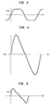
- FIGs. 2-5 shows exemplary waveforms used to drive the phase modulator in FIG. 1.
- FIG. 6 shows a simplified block diagram of one embodiment of a phase and polarization modulated transmitter in accordance with the present invention.
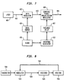
- FIG. 7 shows a simplified block diagram of an alternative embodiment of the phase and polarization modulated transmitter where the phase and polarization modulation is accomplished in a single in accordance with the present invention.
- FIG. 8 is a simplified block diagram of a transmission system architecture embodying principles of the invention.
- FIG. 1 shows a simplified block diagram of an exemplary arrangement facilitating the practice of the invention.
- the invention includes a laser 100 for producing a continuous wave ("CW") optical signal 101.
- the optical signal 101 is transmitted to a data modulator 102 that modulates the signal to impart information in a conventional manner to produce a modulated optical information signal 103.
- the data modulator 102 receives the signal data 116 to be imparted to the optical signal 101 from a data source 104.
- Data modulator 102 modulates the optical signal 101 at a frequency determined by a clock 106 via a clock signal on line 117.
- the optical information signal 103 is transmitted from data modulator 102 to a phase modulator 108.
- Phase modulator 108 modulates the phase of the optical carrier (i.e., optical signal 101) onto which the data signal has been modulated.
- phase modulator 108 is driven by a periodic waveform 112.
- Periodic waveform 112 is generated using a waveform generator 110 and a variable-delay element.
- Waveform generator 110 generates a periodic control signal 111.
- the periodic control signal 111 has the same fundamental frequency as a clock 106, and is furthermore phase-locked to clock 106 via a clock signal on line 118.
- variable-delay element 107 The relative delay between the signal data 116 carried on optical information signal 103 and the periodic waveform 112 is determined by variable-delay element 107. As shown in FIG. 1, variable-delay element 107 is coupled to receive periodic control signal 111 from waveform generator 110. The delay is set to facilitate the optimization of the transmission performance of a system using the phase modulator described above. For example, the delay may be set to maximize the signal-to-noise ratio or Q-Factor received at a remote receiver. It is emphasized, however, that variable-delay element 107 is considered optional and may be deleted in some applications of the invention.
- E ( t ) A ( t ) e i ( ⁇ t + ⁇ ( t )) where ⁇ is the optical carrier frequency, ⁇ (t) is the phase angle of the optical signal 105 and A (t) is assumed to be real field amplitude and include the intensity modulation.
- ⁇ ( t ) ⁇ + ⁇ ⁇ ( ⁇ t + ⁇ )
- ⁇ the optical phase modulation index
- ⁇ the phase modulation frequency (corresponding to the bit rate)
- ⁇ describes the relative delay between the PM and the data bits
- ⁇ denotes an arbitrary offset.
- the time function f(t) is generated in the phase waveform generator 110.
- amplitude errors may be caused by a variety of factors including amplifier noise, chromatic dispersion and fiber nonlinearities.
- the AM generated from the conversion of polarization and phase modulation which is caused by an interaction between the signal and the chromatic dispersion and nonlinear index of refraction of the fiber, can be beneficial if the phase of the AM is properly adjusted with respect to the data.
- a graphical method for evaluating the impact of impairments to a signal other than noise is known to those of ordinary skill in the art as an eye diagram.
- the AM that is generated can "open" the eye of the received data and compensate for eye closure caused by amplitude types of errors. By properly adjusting the phase ⁇ , the eye opening can be improved.
- the phase ⁇ is adjusted via the variable-delay element 107 until the signal-to-noise ratio ("SNR") of the received optical signal is optimized.
- SNR signal-to-noise ratio
- FIGs. 2-5 shows examples of periodic waveforms f(t) used to phase modulate the optical information signal 103 (FIG. 1).
- the waveform shown in FIG. 2 is a simple sinusoidal signal as disclosed in the aforementioned co-pending application.
- the waveforms shown in FIGs. 3-5 are examples of waveforms that include more elaborate harmonic content which are designed to improve on the performance of optical transmission systems in accordance with the principles of the present invention.
- the waveforms shown in FIGs. 4 and 5 are provided as examples of a practical approximation to a ramp function.
- FIG. 6 shows an alternative embodiment of the invention in which a polarization modulation function has been added to the output of the apparatus shown in FIG. 1.
- Laser 300 for produces a CW optical signal 301.
- the optical signal 301 is transmitted to a data modulator 302 that modulates the signal to impart information thereto in a conventional fashion, producing a modulated optical information signal 303.
- the data modulator 302 receives the data to be imparted to the optical signal 301 from a data source 304 on line 335 and modulates the optical signal 301 at a frequency determined by a clock 306 via clock signal 337.
- the optical information signal 303 is transmitted from the data modulator 302 to a phase modulator 308 which modulates the phase of the optical information signal 303.
- Phase modulator 308 operates as described above when referring to FIG. 1.
- the phase modulated signal 330 emerging from phase modulator 308 is directed to a polarization modulator 311 which modulates the state-of-polarization ("SOP") of the optical information signal 303.
- Polarization modulator 311 operates to change the SOP of the optical information signal in such a way that it has no preferred SOP averaged over the modulation period. Accordingly, the output signal 314 has a degree of polarization that is substantially zero and is said to be polarization scrambled.
- the SOP of optical information signal 303 traces a complete great circle on the Poincaré sphere.
- the SOP of the optical signal may reciprocate along the Poincaré sphere. In either case, the average value of the SOP over each modulation cycle is substantially equal to zero.
- a polarization modulator 108 that may be employed in the present invention is disclosed in U.S. Patent No. 5,327,511, particularly in figure 3 of that reference.
- the polarization modulator 311 is driven a periodic waveform 316 generated by a polarization waveform generator 312.
- periodic waveform 316 may take any of the exemplary forms shown in FIGs. 2-5, in accordance with the principles of the invention.
- the periodic waveform has the same fundamental frequency as clock 306, and is furthermore phase locked to clock 306.
- the relative delay between signal data modulated onto signal 303 and the periodic waveform 315 generated in 312 is set by a variable-delay element 313.
- the manner in which the periodic waveforms 317 and 316 drive the phase modulator 308 and polarization modulator 311, respectively, may be described by examining the electric field of the optical signal on which the phase modulator acts.
- every possible SOP of an optical signal having these electric field components can be obtained by varying the ratio A x /A y while maintaining the value of (A x 2 + A y 2 ) constant and varying the relative phase difference ⁇ x - ⁇ y between 0 and 2 ⁇ .
- the polarization modulator 308 serves to modulate the SOP of the optical signal by varying only the phases ⁇ x and ⁇ y , which is sufficient to provide a SOP whose average value over a modulation cycle is zero.
- the phase modulator 308 imparts the same phase modulation to both the x and y components of the optical signal 303 since they have the same phase modulation index ⁇ . Accordingly, the phase modulator 308 modulates the optical phase of signal 303 without modulating the polarization of the optical signal.
- the reason the phase modulator 308 does not modulate the polarization is because the polarization modulation of the optical signal is proportional to the difference between the phases ⁇ x and ⁇ y and this difference is unaffected by the phase modulator 308 since it modulates both ⁇ x and ⁇ y by equal amounts.
- polarization dependent phenomena are mediated by polarization dependent loss ("PDL") in the transmission medium, and as such, can fluctuate over time, causing additional signal fading.
- PDL polarization dependent loss
- polarization independent phenomena is mediated by chromatic dispersion and/or a nonlinear index of refraction in the transmission fiber and as such does not fluctuate in time.
- the AM generated by modulating the polarization at the bit rate does not significantly contribute to signal fading
- AM modulation can occur at the modulation frequency ⁇ and harmonics thereof (i.e., 2 ⁇ , 3 ⁇ , ).
- the amount of AM, and the phase relationship of the AM with respect to the phase of the polarization modulation depends, in general, on the orientation of the loss axis of the PDL element with respect to the polarization modulation axis.
- the amount of AM that occurs will fluctuate with time because the state-of-polarization of the optical signal varies with time.
- a typical fiber optic receiver has an electrical bandwidth of about 60% of the data rate. Thus, some of the AM occurring at the bit rate can pass through the receiver to the decision circuit and effect the BER.
- the BER is unaffected by AM that occurs at harmonics of the bit rate having a frequency of 2 ⁇ or higher since these harmonics are blocked by the receiver.
- the majority of the AM modulation occurs at harmonics of the modulation frequency (i.e., 2 ⁇ and higher) and not at the fundamental modulation frequency ⁇ .
- the AM generated by modulating the polarization at the bit rate does not significantly contribute to signal fading, assuming a properly designed optical receiver is employed.
- the AM generated by the conversion of polarization and/or phase modulation as a result of the chromatic dispersion and/or the nonlinear index of refraction of the optical fiber can be beneficial if the polarization modulation is performed at the bit rate.
- phase modulator 308 and the polarization modulator 311 shown in FIG. 6 are both incorporated into a single unit 408.
- a single variable-delay element 407 is used to vary both the polarization modulation and the optical phase modulation.
- the polarization modulation is given by the difference in the angles ⁇ 1 - ⁇ 2 and is adjusted for a low degree of polarization.
- the excess phase modulation is given by the average of the two angles ( ⁇ 1 + ⁇ 2 )/2.
- FIG. 8 is a simplified block diagram of a transmission system architecture embodying principles of the invention.
- a transmitter 500 which includes a laser, data source, data modulator, and clock (not shown), is coupled to a modulator 510.
- modulator 510 includes both phase and polarization modulation, that is, it is configured in a similar arrangement as elements shown in FIG. 4 and described above, and thus, embodies the advantageous characteristics provided therein.
- modulator 510 may only embody the characteristics of the phase modulator as shown in FIG. 1 (i.e., not implementing the above-described polarization modulation).
- a receiver 520 is coupled to modulator 510 via a forward transmission path 530.
- a monitor 550 is coupled to receiver 520 for measuring performance characteristics of the optical signal received at the receiver 520.
- Monitor 550 may be, for example, a conventional bit-error-rate detector.
- a return telemetry path 540 couples monitor 550 to modulator 510.
- Such performance characteristics include SNR or Q-factor.
- the measured performance characteristic may be transmitted via telemetry path 540 to modulator 510.
- the phase ⁇ (i.e., relative delay) parameter in Equation 2 may then be adjusted in modulator 510 in response to the measured performance characteristic in order to optimize transmission system performance.
Landscapes
- Physics & Mathematics (AREA)
- Electromagnetism (AREA)
- Engineering & Computer Science (AREA)
- Computer Networks & Wireless Communication (AREA)
- Signal Processing (AREA)
- Optical Communication System (AREA)
Applications Claiming Priority (2)
| Application Number | Priority Date | Filing Date | Title |
|---|---|---|---|
| US580869 | 1995-12-29 | ||
| US08/580,869 US6310709B1 (en) | 1995-12-29 | 1995-12-29 | Synchronous polarization and phase modulation using a periodic waveform with complex harmonics for improved performance of optical transmission systems |
Publications (3)
| Publication Number | Publication Date |
|---|---|
| EP0782282A2 true EP0782282A2 (fr) | 1997-07-02 |
| EP0782282A3 EP0782282A3 (fr) | 2000-10-11 |
| EP0782282B1 EP0782282B1 (fr) | 2004-11-10 |
Family
ID=24322912
Family Applications (1)
| Application Number | Title | Priority Date | Filing Date |
|---|---|---|---|
| EP96120627A Expired - Lifetime EP0782282B1 (fr) | 1995-12-29 | 1996-12-20 | Modulation de polarisation et de phase synchrone utilisant une forme d'onde périodique à harmoniques complexes pour améliorer la performance de systèmes de transmission optiques |
Country Status (9)
| Country | Link |
|---|---|
| US (1) | US6310709B1 (fr) |
| EP (1) | EP0782282B1 (fr) |
| JP (1) | JP4031076B2 (fr) |
| KR (1) | KR100221265B1 (fr) |
| AU (1) | AU725807B2 (fr) |
| CA (1) | CA2193754C (fr) |
| DE (1) | DE69633816T2 (fr) |
| MX (1) | MX9606712A (fr) |
| TW (1) | TW315551B (fr) |
Cited By (4)
| Publication number | Priority date | Publication date | Assignee | Title |
|---|---|---|---|---|
| EP1052792A3 (fr) * | 1999-05-14 | 2001-09-19 | Nec Corporation | Emetteur optique |
| US6459518B1 (en) | 1998-06-12 | 2002-10-01 | Kdd Corporation | Optical transmitting apparatus |
| EP0964538A3 (fr) * | 1998-06-09 | 2004-11-17 | NEC Corporation | Emetteur optique et système de transmission optique avec modulation de la polarisation |
| EP1712948A1 (fr) | 2005-04-15 | 2006-10-18 | Alcatel | Circuit d'attaque à faible consommation de puissance pour un embrouilleur de polarisation |
Families Citing this family (28)
| Publication number | Priority date | Publication date | Assignee | Title |
|---|---|---|---|---|
| US6680928B1 (en) * | 1997-07-22 | 2004-01-20 | Ericsson Inc. | Communications system and method for multi-carrier orthogonal coding |
| US6549311B1 (en) * | 1999-07-14 | 2003-04-15 | Lucent Technologies Inc. | Wave division multiplexing channel telemetry by phase modulation |
| JP3627628B2 (ja) * | 2000-06-20 | 2005-03-09 | Kddi株式会社 | 光データ伝送方法及びシステム、光送信装置及び方法並びに光交換機 |
| US6904157B2 (en) * | 2000-08-10 | 2005-06-07 | Shima System Co., Ltd. | Structure around a speaker unit and applied electric or electronic apparatus thereof |
| EP1191716A3 (fr) * | 2000-09-26 | 2004-12-15 | Siemens Aktiengesellschaft | Méthode d'introduction synchronisée en phase d'un signal d'impulsion optique avec un signal électrique d'informations |
| US6633712B2 (en) * | 2001-03-16 | 2003-10-14 | Sowilo Networks, Inc. | Method and system for dispersion maps and enhanced distributed gain effect in long haul telecommunications |
| US7085500B2 (en) * | 2001-04-30 | 2006-08-01 | Lockheed Martin Corp. | Programmable optical vector modulator and method for use in coherent optical communications |
| US7483639B2 (en) * | 2001-05-10 | 2009-01-27 | Fujitsu Limited | Method and system for transmitting information in an optical communication system using distributed amplification |
| US7200344B1 (en) | 2001-05-10 | 2007-04-03 | Fujitsu Limited | Receiver and method for a multichannel optical communication system |
| US7039067B2 (en) * | 2001-07-30 | 2006-05-02 | Dorsal Networks, Inc. | Methods and systems for hybrid interfaces and architectures for optical communications |
| US6714695B2 (en) | 2001-09-17 | 2004-03-30 | Dorsal Networks, Inc. | Optical transmission system employing auto-synchronized chirped return-to-zero transmitter |
| US7019882B1 (en) | 2002-03-21 | 2006-03-28 | Lockheed Martin Corporation | Generation of M-ary digital signaling constellations directly at lightwave frequencies |
| JP4053389B2 (ja) * | 2002-09-19 | 2008-02-27 | 富士通株式会社 | 光信号対雑音比のモニタ方法およびそれを用いた光伝送システム |
| US20040057734A1 (en) * | 2002-09-25 | 2004-03-25 | Lucent Technologies, Inc. | Method and system for reducing transmission penalties associated with ghost pulses |
| US7382984B2 (en) | 2002-10-03 | 2008-06-03 | Nortel Networks Limited | Electrical domain compensation of optical dispersion in an optical communications system |
| US7352688B1 (en) * | 2002-12-31 | 2008-04-01 | Cisco Technology, Inc. | High data rate wireless bridging |
| US7573902B2 (en) | 2003-08-28 | 2009-08-11 | The Boeing Company | Fibre channel interface unit |
| US20050053022A1 (en) * | 2003-08-28 | 2005-03-10 | The Boeing Company | Encoding and merging multiple data streams of fibre channel network |
| US7729374B2 (en) * | 2003-08-28 | 2010-06-01 | The Boeing Company | Fibre channel interface apparatus and methods |
| US20080170862A1 (en) * | 2007-01-12 | 2008-07-17 | Vassilieva Olga I | Monitoring Polarization Of A Signal Communicated According To Polarization Multiplexing |
| US8369442B2 (en) * | 2007-01-12 | 2013-02-05 | Fujitsu Limited | Communicating a signal according to ASK modulation and PSK modulation |
| JP5298194B2 (ja) * | 2008-07-31 | 2013-09-25 | テレフオンアクチーボラゲット エル エム エリクソン(パブル) | 光信号変調方式 |
| JP5141498B2 (ja) * | 2008-10-30 | 2013-02-13 | 富士通株式会社 | 光送受信システム,光送信器,光受信器および光送受信方法 |
| CN101860500B (zh) * | 2009-04-13 | 2013-10-09 | 华为技术有限公司 | 一种产生、接收相位偏振调制信号的方法、装置和系统 |
| JP5499632B2 (ja) * | 2009-10-28 | 2014-05-21 | 富士通株式会社 | 光送信機、光送受信システム、光送信方法、および、光送受信方法 |
| US8958702B2 (en) * | 2011-03-17 | 2015-02-17 | Fujitsu Limited | System and method for reducing interference of a polarization multiplexed signal |
| JP2014096663A (ja) * | 2012-11-08 | 2014-05-22 | Fujitsu Ltd | 光伝送システム、光送信器、光受信器及び光伝送方法 |
| DE102013014789A1 (de) | 2013-06-19 | 2014-12-24 | Günter Grau | Vorrichtung zur Veränderung und Messung der Polarisation von Radiowellen sowie Anwendung auf Messung von Drehwinkeln und Verschiebungen |
Citations (1)
| Publication number | Priority date | Publication date | Assignee | Title |
|---|---|---|---|---|
| US5327511A (en) | 1993-06-18 | 1994-07-05 | At&T Bell Laboratories | Apparatus and method employing fast polarization modulation to reduce effects of polarization hole burning and polarization dependent loss |
Family Cites Families (12)
| Publication number | Priority date | Publication date | Assignee | Title |
|---|---|---|---|---|
| GB8808043D0 (en) | 1988-04-06 | 1988-05-25 | British Telecomm | Methods & apparatus for transmitting information |
| DE58908768D1 (de) | 1988-09-30 | 1995-01-26 | Siemens Ag | Verfahren zum synchronisierten Umtasten eines Polarisationszustandes eines optischen Sendesignals eines optischen Übertragungssystems mit Überlagerungsempfang und Vorrichtung zur Durchführung des Verfahrens. |
| US4968968A (en) * | 1989-11-09 | 1990-11-06 | Hughes Aircraft Company | Transmitter phase and amplitude correction for linear FM systems |
| JP3223562B2 (ja) * | 1992-04-07 | 2001-10-29 | 株式会社日立製作所 | 光送信装置、光伝送装置および光変調器 |
| US5329260A (en) * | 1992-07-17 | 1994-07-12 | Ii Morrow Inc. | Numerically-controlled modulated oscillator and modulation method |
| US5321543A (en) * | 1992-10-20 | 1994-06-14 | General Instrument Corporation | Apparatus and method for linearizing an external optical modulator |
| US5345331A (en) | 1993-04-13 | 1994-09-06 | At&T Bell Laboratories | Technique for reducing polarization dependent gain in an amplified optical transmission system |
| US5309535A (en) | 1993-04-30 | 1994-05-03 | At&T Bell Laboratories | Apparatus and method utilizing a rotating waveplate for reducing polarization dependent hole-burning in an amplified optical transmission system |
| US5309530A (en) | 1993-04-30 | 1994-05-03 | At&T Bell Laboratories | Technique utilizing stress-induced birefringence for reducing polarization dependent hole-burning in an amplified optical transmission system |
| US5361270A (en) | 1993-08-18 | 1994-11-01 | At&T Bell Laboratories | Apparatus and method employing polarization modulation to reduce effects of polarization hole burning and/or polarization dependent loss |
| US5526162A (en) * | 1994-09-27 | 1996-06-11 | At&T Corp. | Synchronous polarization and phase modulation for improved performance of optical transmission systems |
| US5473458A (en) * | 1994-12-27 | 1995-12-05 | At&T Corp. | Soliton data transmission using non-soliton transmitter |
-
1995
- 1995-12-29 US US08/580,869 patent/US6310709B1/en not_active Expired - Fee Related
-
1996
- 1996-10-12 TW TW085112475A patent/TW315551B/zh active
- 1996-12-19 MX MX9606712A patent/MX9606712A/es unknown
- 1996-12-20 JP JP34073896A patent/JP4031076B2/ja not_active Expired - Fee Related
- 1996-12-20 EP EP96120627A patent/EP0782282B1/fr not_active Expired - Lifetime
- 1996-12-20 DE DE69633816T patent/DE69633816T2/de not_active Expired - Lifetime
- 1996-12-23 CA CA002193754A patent/CA2193754C/fr not_active Expired - Fee Related
- 1996-12-24 AU AU76501/96A patent/AU725807B2/en not_active Ceased
- 1996-12-28 KR KR1019960075232A patent/KR100221265B1/ko not_active Expired - Fee Related
Patent Citations (1)
| Publication number | Priority date | Publication date | Assignee | Title |
|---|---|---|---|---|
| US5327511A (en) | 1993-06-18 | 1994-07-05 | At&T Bell Laboratories | Apparatus and method employing fast polarization modulation to reduce effects of polarization hole burning and polarization dependent loss |
Cited By (6)
| Publication number | Priority date | Publication date | Assignee | Title |
|---|---|---|---|---|
| EP0964538A3 (fr) * | 1998-06-09 | 2004-11-17 | NEC Corporation | Emetteur optique et système de transmission optique avec modulation de la polarisation |
| US6459518B1 (en) | 1998-06-12 | 2002-10-01 | Kdd Corporation | Optical transmitting apparatus |
| EP1052792A3 (fr) * | 1999-05-14 | 2001-09-19 | Nec Corporation | Emetteur optique |
| EP1712948A1 (fr) | 2005-04-15 | 2006-10-18 | Alcatel | Circuit d'attaque à faible consommation de puissance pour un embrouilleur de polarisation |
| CN100368838C (zh) * | 2005-04-15 | 2008-02-13 | 阿尔卡特公司 | 用于偏振扰频器的低功率驱动器电路 |
| US7450289B2 (en) | 2005-04-15 | 2008-11-11 | Alcatel | Low power driver circuit for a polarization scrambler |
Also Published As
| Publication number | Publication date |
|---|---|
| DE69633816T2 (de) | 2005-03-17 |
| DE69633816D1 (de) | 2004-12-16 |
| US6310709B1 (en) | 2001-10-30 |
| JP4031076B2 (ja) | 2008-01-09 |
| EP0782282B1 (fr) | 2004-11-10 |
| AU725807B2 (en) | 2000-10-19 |
| JPH09197354A (ja) | 1997-07-31 |
| AU7650196A (en) | 1997-07-03 |
| EP0782282A3 (fr) | 2000-10-11 |
| CA2193754A1 (fr) | 1997-06-30 |
| KR970056081A (ko) | 1997-07-31 |
| CA2193754C (fr) | 2002-12-17 |
| TW315551B (fr) | 1997-09-11 |
| KR100221265B1 (ko) | 1999-09-15 |
| MX9606712A (es) | 1997-06-28 |
Similar Documents
| Publication | Publication Date | Title |
|---|---|---|
| US6310709B1 (en) | Synchronous polarization and phase modulation using a periodic waveform with complex harmonics for improved performance of optical transmission systems | |
| EP0704996B1 (fr) | Modulation synchrone de polarisation et de phase pour améliorer la performance d'un système de communication optique | |
| US6744992B2 (en) | Synchronous amplitude modulation for improved performance of optical transmission systems | |
| US5227908A (en) | Optical communication apparatus using intensity modulation | |
| MXPA96006712A (es) | Polarizacion sincrona y modulacion de fase utilizando una forma de onda periodica con armonicos complejos para mejorado desempeño de sistemas de transmision optica | |
| US6407845B2 (en) | Optical transmitter and optical transmission system | |
| US5946119A (en) | Wavelength division multiplexed system employing optimal channel modulation | |
| EP0643497A1 (fr) | Transmission optique avec conversion FM/AM induite par dispersion avec stabilisation induite par les nonlinéarités | |
| US8131157B2 (en) | Method and apparatus for generating signals with increased dispersion tolerance using a directly modulated laser transmitter | |
| US20040021829A1 (en) | Multi-level optical signal generation | |
| EP0660549A1 (fr) | Emetteur de données à deux longeurs d'onde pour réduire les évanouissements dans un système de transmission optique | |
| US5872647A (en) | Optical transmitting terminal | |
| JP2000068940A (ja) | 光送信装置 | |
| EP0845175B1 (fr) | Compensation de la dispersion | |
| US20040161245A1 (en) | Synchronous amplitude modulation for improved performance of optical transmission systems | |
| US7050658B2 (en) | Method and apparatus for reducing system deterioration caused by polarization effects | |
| US20030218790A1 (en) | Chirp control in a high speed optical transmission system | |
| JP2982402B2 (ja) | 光通信装置 | |
| US7133621B1 (en) | Optical communication with phase encoding and phase shifting | |
| HK1001150A (en) | Synchronous polarization and phase modulation using a periodic waveform with complex harmonics for improved perfomance of optical transmission systems | |
| AU746848B2 (en) | Synchronous polarization and phase modulation for improved performance of optical transmission systems | |
| JPS6248823A (ja) | 光通信方法及び光送信装置 | |
| JPH05244096A (ja) | 光送信装置および光通信装置 |
Legal Events
| Date | Code | Title | Description |
|---|---|---|---|
| PUAI | Public reference made under article 153(3) epc to a published international application that has entered the european phase |
Free format text: ORIGINAL CODE: 0009012 |
|
| AK | Designated contracting states |
Kind code of ref document: A2 Designated state(s): DE FR GB IT NL SE |
|
| PUAL | Search report despatched |
Free format text: ORIGINAL CODE: 0009013 |
|
| AK | Designated contracting states |
Kind code of ref document: A3 Designated state(s): DE FR GB IT NL SE |
|
| RIC1 | Information provided on ipc code assigned before grant |
Free format text: 7H 04B 10/135 A, 7H 04B 10/155 B, 7H 04B 10/18 B |
|
| 17P | Request for examination filed |
Effective date: 20010411 |
|
| RAP1 | Party data changed (applicant data changed or rights of an application transferred) |
Owner name: TYCOM (US) INC. |
|
| 17Q | First examination report despatched |
Effective date: 20020709 |
|
| RAP1 | Party data changed (applicant data changed or rights of an application transferred) |
Owner name: TYCO TELECOMMUNICATIONS (US) INC. |
|
| GRAP | Despatch of communication of intention to grant a patent |
Free format text: ORIGINAL CODE: EPIDOSNIGR1 |
|
| REG | Reference to a national code |
Ref country code: HK Ref legal event code: WD Ref document number: 1001150 Country of ref document: HK |
|
| GRAS | Grant fee paid |
Free format text: ORIGINAL CODE: EPIDOSNIGR3 |
|
| GRAA | (expected) grant |
Free format text: ORIGINAL CODE: 0009210 |
|
| AK | Designated contracting states |
Kind code of ref document: B1 Designated state(s): DE FR GB IT NL SE |
|
| PG25 | Lapsed in a contracting state [announced via postgrant information from national office to epo] |
Ref country code: SE Free format text: LAPSE BECAUSE OF FAILURE TO SUBMIT A TRANSLATION OF THE DESCRIPTION OR TO PAY THE FEE WITHIN THE PRESCRIBED TIME-LIMIT Effective date: 20041110 Ref country code: NL Free format text: LAPSE BECAUSE OF FAILURE TO SUBMIT A TRANSLATION OF THE DESCRIPTION OR TO PAY THE FEE WITHIN THE PRESCRIBED TIME-LIMIT Effective date: 20041110 |
|
| REG | Reference to a national code |
Ref country code: GB Ref legal event code: FG4D |
|
| PGFP | Annual fee paid to national office [announced via postgrant information from national office to epo] |
Ref country code: NL Payment date: 20041205 Year of fee payment: 9 |
|
| REF | Corresponds to: |
Ref document number: 69633816 Country of ref document: DE Date of ref document: 20041216 Kind code of ref document: P |
|
| NLV1 | Nl: lapsed or annulled due to failure to fulfill the requirements of art. 29p and 29m of the patents act | ||
| PLBE | No opposition filed within time limit |
Free format text: ORIGINAL CODE: 0009261 |
|
| STAA | Information on the status of an ep patent application or granted ep patent |
Free format text: STATUS: NO OPPOSITION FILED WITHIN TIME LIMIT |
|
| 26N | No opposition filed |
Effective date: 20050811 |
|
| ET | Fr: translation filed | ||
| PGFP | Annual fee paid to national office [announced via postgrant information from national office to epo] |
Ref country code: IT Payment date: 20121220 Year of fee payment: 17 Ref country code: GB Payment date: 20121227 Year of fee payment: 17 |
|
| PGFP | Annual fee paid to national office [announced via postgrant information from national office to epo] |
Ref country code: FR Payment date: 20130110 Year of fee payment: 17 |
|
| PGFP | Annual fee paid to national office [announced via postgrant information from national office to epo] |
Ref country code: DE Payment date: 20121231 Year of fee payment: 17 |
|
| REG | Reference to a national code |
Ref country code: DE Ref legal event code: R119 Ref document number: 69633816 Country of ref document: DE |
|
| GBPC | Gb: european patent ceased through non-payment of renewal fee |
Effective date: 20131220 |
|
| REG | Reference to a national code |
Ref country code: DE Ref legal event code: R079 Ref document number: 69633816 Country of ref document: DE Free format text: PREVIOUS MAIN CLASS: H04B0010135000 Ipc: H04B0010250000 |
|
| REG | Reference to a national code |
Ref country code: FR Ref legal event code: ST Effective date: 20140829 |
|
| REG | Reference to a national code |
Ref country code: DE Ref legal event code: R119 Ref document number: 69633816 Country of ref document: DE Effective date: 20140701 Ref country code: DE Ref legal event code: R079 Ref document number: 69633816 Country of ref document: DE Free format text: PREVIOUS MAIN CLASS: H04B0010135000 Ipc: H04B0010250000 Effective date: 20140901 |
|
| PG25 | Lapsed in a contracting state [announced via postgrant information from national office to epo] |
Ref country code: DE Free format text: LAPSE BECAUSE OF NON-PAYMENT OF DUE FEES Effective date: 20140701 |
|
| PG25 | Lapsed in a contracting state [announced via postgrant information from national office to epo] |
Ref country code: GB Free format text: LAPSE BECAUSE OF NON-PAYMENT OF DUE FEES Effective date: 20131220 Ref country code: FR Free format text: LAPSE BECAUSE OF NON-PAYMENT OF DUE FEES Effective date: 20131231 |
|
| PG25 | Lapsed in a contracting state [announced via postgrant information from national office to epo] |
Ref country code: IT Free format text: LAPSE BECAUSE OF NON-PAYMENT OF DUE FEES Effective date: 20131231 |
|
| PG25 | Lapsed in a contracting state [announced via postgrant information from national office to epo] |
Ref country code: IT Free format text: LAPSE BECAUSE OF NON-PAYMENT OF DUE FEES Effective date: 20131220 |