EP0782677B2 - Douille de serrage pour tuyaux a fluide sous pression - Google Patents
Douille de serrage pour tuyaux a fluide sous pression Download PDFInfo
- Publication number
- EP0782677B2 EP0782677B2 EP95934634A EP95934634A EP0782677B2 EP 0782677 B2 EP0782677 B2 EP 0782677B2 EP 95934634 A EP95934634 A EP 95934634A EP 95934634 A EP95934634 A EP 95934634A EP 0782677 B2 EP0782677 B2 EP 0782677B2
- Authority
- EP
- European Patent Office
- Prior art keywords
- plastic insert
- clamping sleeve
- base member
- pressure hose
- sleeve according
- Prior art date
- Legal status (The legal status is an assumption and is not a legal conclusion. Google has not performed a legal analysis and makes no representation as to the accuracy of the status listed.)
- Expired - Lifetime
Links
- 239000004033 plastic Substances 0.000 claims description 57
- 229920003023 plastic Polymers 0.000 claims description 57
- 229910052751 metal Inorganic materials 0.000 claims description 32
- 239000002184 metal Substances 0.000 claims description 32
- -1 polyoxy-methylene Polymers 0.000 claims description 5
- 229930040373 Paraformaldehyde Natural products 0.000 claims description 3
- HCWCAKKEBCNQJP-UHFFFAOYSA-N magnesium orthosilicate Chemical compound [Mg+2].[Mg+2].[O-][Si]([O-])([O-])[O-] HCWCAKKEBCNQJP-UHFFFAOYSA-N 0.000 claims description 3
- 229910052919 magnesium silicate Inorganic materials 0.000 claims description 3
- 235000019792 magnesium silicate Nutrition 0.000 claims description 3
- 239000000391 magnesium silicate Substances 0.000 claims description 3
- 239000000463 material Substances 0.000 claims description 3
- 239000011256 inorganic filler Substances 0.000 claims description 2
- 229910003475 inorganic filler Inorganic materials 0.000 claims description 2
- 239000001023 inorganic pigment Substances 0.000 claims description 2
- 210000002445 nipple Anatomy 0.000 description 6
- 238000009954 braiding Methods 0.000 description 3
- 230000002093 peripheral effect Effects 0.000 description 3
- 238000007789 sealing Methods 0.000 description 3
- 239000004698 Polyethylene Substances 0.000 description 2
- 239000012530 fluid Substances 0.000 description 2
- 238000009434 installation Methods 0.000 description 2
- 239000002991 molded plastic Substances 0.000 description 2
- 229920000573 polyethylene Polymers 0.000 description 2
- 229920006324 polyoxymethylene Polymers 0.000 description 2
- 241000538562 Banjos Species 0.000 description 1
- 229910000831 Steel Inorganic materials 0.000 description 1
- 239000000654 additive Substances 0.000 description 1
- 230000015572 biosynthetic process Effects 0.000 description 1
- 238000010276 construction Methods 0.000 description 1
- 230000002349 favourable effect Effects 0.000 description 1
- 238000000034 method Methods 0.000 description 1
- 230000000149 penetrating effect Effects 0.000 description 1
- 230000001603 reducing effect Effects 0.000 description 1
- 239000010959 steel Substances 0.000 description 1
Images

Classifications
-
- F—MECHANICAL ENGINEERING; LIGHTING; HEATING; WEAPONS; BLASTING
- F16—ENGINEERING ELEMENTS AND UNITS; GENERAL MEASURES FOR PRODUCING AND MAINTAINING EFFECTIVE FUNCTIONING OF MACHINES OR INSTALLATIONS; THERMAL INSULATION IN GENERAL
- F16L—PIPES; JOINTS OR FITTINGS FOR PIPES; SUPPORTS FOR PIPES, CABLES OR PROTECTIVE TUBING; MEANS FOR THERMAL INSULATION IN GENERAL
- F16L33/00—Arrangements for connecting hoses to rigid members; Rigid hose-connectors, i.e. single members engaging both hoses
- F16L33/20—Undivided rings, sleeves, or like members contracted on the hose or expanded inside the hose by means of tools; Arrangements using such members
- F16L33/207—Undivided rings, sleeves, or like members contracted on the hose or expanded inside the hose by means of tools; Arrangements using such members only a sleeve being contracted on the hose
- F16L33/2071—Undivided rings, sleeves, or like members contracted on the hose or expanded inside the hose by means of tools; Arrangements using such members only a sleeve being contracted on the hose the sleeve being a separate connecting member
- F16L33/2073—Undivided rings, sleeves, or like members contracted on the hose or expanded inside the hose by means of tools; Arrangements using such members only a sleeve being contracted on the hose the sleeve being a separate connecting member directly connected to the rigid member
- F16L33/2076—Undivided rings, sleeves, or like members contracted on the hose or expanded inside the hose by means of tools; Arrangements using such members only a sleeve being contracted on the hose the sleeve being a separate connecting member directly connected to the rigid member by plastic deformation
Definitions
- the invention relates to a ferrule for Connection of a metal braided pressure hose.
- the invention further relates to a metal braid Pressure hose.
- Metal braided pressure hoses are used in particular in hydraulic systems or devices in which a hydraulic connection between mutually movable parts has to be established.
- a master brake cylinder attached to the handlebar to the front brake, which is usually attached to the lower part of the front fork of a motorcycle, by means of a metal braided pressure hose, in order to actuate the brake piston or pistons by means of hydraulic pressure and thereby to connect the brake pads to a torque proof connection to the front wheel To be able to put on the brake disc.
- Metal braided pressure hoses are also used in the field of construction machines, for example in excavators, to connect their hydraulically operated piston / cylinder units for lifting and lowering the excavator bucket with a unit that generates hydraulic pressure centrally in the excavator.
- metal braided pressure hoses are used in hydraulically operated machine tools, which are often movable against each other. in particular have rotatable components.
- Pressure hose with a connection fitting will usually be one to be connected Crimp sleeve to be inserted at the end of the pressure hose used, then after pushing on the pressure hose on the connection fitting or from the latter protruding connecting piece in the radial direction is squeezed together, creating a pressure-resistant Crimped connection between the pressure hose and the connection fitting is created.
- a crimp connection with a crimp sleeve is, for example from DE 41 02 047 C2 or from EP 0 258 524 B1 is known.
- the invention has for its object a To provide a solution that enables one to be ready for connection metal braided pressure hose to produce the vibration has an increased lifespan.
- This task is according to the invention through the characteristics of claim 1.
- the task is according to the invention also by a metal braid Pressure hose loosened, its connection with a connection fitting by an inventive Crimp sleeve is made.
- the plastic insert of the invention Crimp sleeve ensures due to more favorable friction conditions for a significantly reduced mechanical load the metal braiding of the Pressure hose especially in the critical inlet area the ferrule.
- the durability of the metal braid casing and thus the pressure hose overall is thus significantly increased.
- the inside diameter of the Plastic insert from its axially inner end slightly larger than the inside diameter of the section of the base body of the crimp sleeve, which itself connects axially to the plastic insert.
- the plastic insert has a crimp sleeve on its axially inner end portion a radially outward protruding, circumferential projection, which in a corresponding shaped ring groove in the inner surface of the Basic body engages. This formation of the crimp sleeve ensures a firm fit of the plastic insert in the base body of the crimp sleeve.
- the crimp sleeve encompasses the Plastic insert the inlet end of the body. This modified embodiment also prevents in the event of a sharp kink in the pressure hose in the Damage area is relatively certain the metal braid sheathing.
- Crimp sleeve is the axially outer end the plastic insert is designed as an external hexagon. That way it's much easier than with conventional ready-to-connect pressure hoses possible, the connection fitting opposite the pressure hose to twist, albeit at the connection fitting even attachment surfaces for a tool are. Such twisting of the connection fitting compared to the pressure hose is often necessary around the ready-to-connect pressure hose of the given To be able to adapt the installation situation without the To twist the pressure hose itself.
- the plastic insert of the invention is advantageous Crimp sleeve made of a plastic made of inorganic fillers or pigments contains. Such a plastic sets through its low Coefficient of friction the mechanical stress the metal braid casing in the inlet area the ferrule further down.
- the embodiment is the plastic polyoxymethylene and has a high proportion of magnesium silicate on.
- polyethylene is also a plastic; possibly with appropriate additives, well suited.
- Crimp sleeves have a basic body, at the inlet end a radially outward has circumferential projection, the outer peripheral surface is knurled and the plastic insert is encompassed. These embodiments are particularly in the case of one of the main body of Crimp sleeve molded plastic insert advantageous and lead to a very secure hold of the plastic insert in or on the body.
- Crimp sleeve is the plastic insert not molded onto the base body, but in the latter inserted or pressed in or pressed in.
- An embodiment of an inventive ready to connect, metal braided Pressure hose is characterized in that the Crimp sleeve only along an axial section with the Connection fitting is pressed into which the plastic insert does not extend. This way you avoid that the friction reducing effect of the Plastic insert is deteriorated by the inner surface of the plastic insert in the metal braid casing of the pressure hose presses and there positive connections between the metal braid sheathing and forms the plastic insert.
- a modified embodiment of an inventive Pressure hose is also the axial one Section of the crimp sleeve with the connection fitting pressed in which the axially inner end portion of the Plastic insert is arranged.
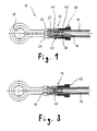
- connection fitting 10 shown on the by means of a crimp sleeve 12 metal braided pressure hose 14 attached shall be.
- the connection fitting 10 is shown as a ring nipple formed as it is for connecting a Brake fluid hose is used by one arranged on the handlebar of a motorcycle Master brake cylinder for the front brake of the motorcycle leads.
- the ring nipple is by means of a not shown Banjo bolt directly on the front brake fastened and placed over the pressure hose 14 Fluid connection between one in the brake arranged brake piston and mounted on the handlebar Master cylinder.
- the ring nipple a through hole axially penetrating it 16, which opens into an annular channel 18.
- On his 1 right end of the ring nipple has one of the through hole 16 penetrated connection piece 20, on which the pressure hose 14 up to a Ring collar 22 executed stop is pushed.
- At 15 is the metal braid sheathing made of steel designated.
- the connecting piece 20 connects axially an external hexagon formed on the body of the ring nipple 24, whose function will be discussed in more detail later will be described.
- an annular groove 26 From the external hexagon 24 seen from the connector 20 axially in succession from an annular groove 26, the one already mentioned Annular collar 22, a cylindrical portion 28 with a reduced diameter compared to the collar 22, one towards the free end, right in FIG. 1 axially tapering cone 30, another cylindrical Section with reduced compared to section 28 Diameter on the outer peripheral surface except for one adjacent to the free end End section several consecutive, revolving Grooves 32 are formed, another itself axially tapering cone 34 and finally with a cylindrical section 36 again reduced diameter.
- the grooves 32 are designed so that you enclose the bottom of the groove concave part has a radius of 0.5 mm, while the convex parts connecting the individual grooves 32 have a radius of 0.2 mm.
- the crimp sleeve 12 shown in the Embodiment about 1.5 times the length of the connecting piece 20 is concentric with Connection piece 20 arranged and surrounds this as well an end section 38 of the pressure hose 14 Completely. It consists of a tubular, metal Base body 40, which in its from the ring nipple trained connection fitting 10 turned away Area with a hollow cylindrical plastic insert 42 is provided, which is in the illustrated embodiment seen axially from the center of the Base body 40 to the connection fitting 10 facing away End of the base body 40 extends in hereinafter referred to as the incoming end. To record of the plastic insert 42 has the base body 40 a larger one along its intended section Inside diameter than in his at the Plastic insert 42 axially adjoining, left in Fig. 1 Area.
- the inside diameter of the plastic insert 42 is slight from its axially inner end larger than the inner diameter of the axially to the Plastic insert 42 adjoining section of the Base body 40.
- the Plastic insert 42 At its axially inner end, the Plastic insert 42 a radially projecting, circumferential projection 44, which in a corresponding shaped, formed in the inner surface of the base body 40 Ring groove 46 engages.
- the plastic insert On its opposite, The plastic insert has an axially outer end 42 one designed as an external hexagon 48 Flange that the inlet end of the base body 40 and engages around an end portion thereof.
- the inside diameter of the plastic insert 42 enlarged in the area in which the external hexagon 48 is formed to the outside continuously, so that the extending through the plastic insert 42 Through recess in the axially outer end section has an almost bell-shaped shape.
- the end region of the base body 40 has one radially outward, circular cylindrical projection 50 on, the outer peripheral surface knurled is. Both this projection 50 and that in the base body 40 internally formed annular groove 46 serve to the in the illustrated embodiment to the Base body 40 molded plastic insert 42 a to give a firm hold. Alternatively, the plastic insert 42 also pressed into the base body 40 or be pressed, then on the knurled projection 50 on the base body 40 can be dispensed with.
- the plastic insert 42 is made of polyoxymethylene with a high proportion of magnesium silicate, which the plastic to further reduce the Friction between the plastic insert 42 and the Metal braiding of the pressure hose 14 is clogged.
- Another one for the plastic insert 42 suitable material is polyethylene.
- Fig. 3 shows the crimp sleeve 12 in one with the connection fitting 10 pressed state. From Fig. 3 it can be seen that the crimp sleeve 12 only in the Area has been radially compressed, in the the plastic insert 42 does not extend. The Pressing process leads to the end section 38 of the pressure hose 14 sealing against the connecting piece 20 is pressed and that of the connection fitting 10 facing end of the ferrule 12 or their Base body 40 in between the external hexagon 24 and the annular collar 22 formed annular groove 26 pressed becomes.
- Crimp sleeve 12 on the connection fitting 10 ensure that the pressed into the annular groove 26 End of the base body 40 a radially inwardly projecting, revolving collar 52 on the after Pressing a form fit with the collar 22 manufactures.
- the fact that the axial section of the Base body 40, in which the plastic insert 42 is arranged is, is not compressed, is on the one hand ensures that there is no friction between the metal braid casing of the pressure hose and the plastic insert 42 positive engagement between the facing surfaces of the metal braid casing and the plastic insert 42 occurs, and on the other hand it excludes that the outer hexagon formed on the plastic insert 42 48 is deformed.
- the external hexagon 48 works together with the trained on the connection fitting 10 External hexagon 24 to twist the Connection fitting 10 compared to an already the crimp sleeve 12 pressed in sealing system Simplify pressure hose 14. Such twisting the connection fitting 10 opposite the pressure hose 14 is often necessary to get one ready-to-connect pressure hose to the existing one Adapt installation situation and thus a disadvantage affect the life of the pressure hose Avoid twisting the pressure hose in itself.
Landscapes
- Engineering & Computer Science (AREA)
- General Engineering & Computer Science (AREA)
- Mechanical Engineering (AREA)
- Joints That Cut Off Fluids, And Hose Joints (AREA)
- Pivots And Pivotal Connections (AREA)
Claims (13)
- Douille de serrage (12) pour le raccordement d'un tuyau souple de pression (14), muni d'un revêtement métallique tressé, comprenant une pièce de raccordement (10), qui possède une tubulure de raccordement (20) servant à enfiler le tuyau souple de pression (14), la douille de serrage (12) présentant un corps de base (40) tubulaire en métal, comprenant une extrémité tournée vers la pièce de raccordement (10) et une extrémité d'entrée opposée et la longueur de la douille de serrage (12) étant suffisante pour entrer complètement la tubulure de raccordement (20), dans laquelle
le corps de base (40) est pourvu d'une garniture en matière plastique (42) principalement tubulaire, s'étendant depuis le centre du corps de base (40) jusqu'à au moins l'extrémité d'entrée du corps de base (40), le diamètre intérieur de la garniture en matière synthétique (42) dans sa portion d'extrémité axialement intérieure par rapport au corps de base (40) correspond, à l'état non raccordé par serrage de la douille de serrage, au moins approximativement au diamètre intérieur du corps de base (40), que ce dernier a dans une zone se raccordant axialement à la garniture de matière synthétique (42), et dont le diamètre intérieur augmente dans sa portion d'extrémité axialement extérieure par rapport au corps de base (40), de façon continue, jusqu'à l'extrémité axialement extérieure. - Douille de serrage selon la revendication 1, caractérisée en ce que le diamètre intérieur de la garniture de matière synthétique (42) est à partir de son extrémité axialement intérieure légèrement plus grand que le diamètre intérieur de la portion du corps de base (40) qui se raccorde à la garniture de matière synthétique (42).
- Douille de serrage selon la revendication 1 ou 2, caractérisée en ce que la garniture de matière synthétique (42) présente, à sa portion d'extrémité axialement intérieure, un collet (44) périphérique faisant saillie radialement vers l'extérieur qui pénètre dans sa gorge annulaire (46) formée en conséquence dans la surface intérieure du corps de base (40).
- Douille de serrage selon l'une quelconque des revendications 1 à 3, caractérisée en ce que la garniture de matière synthétique (42) entoure l'extrémité d'entrée du corps de base (40).
- Douille de serrage selon la revendication 4, caractérisée en ce que l'extrémité axialement extérieure de la garniture de matière synthétique (42) a une forme de tête à six pans intérieurs (48).
- Douille de serrage selon l'une quelconque des revendications précédentes, caractérisée en ce que la garniture en matière synthétique (42) est en une matière synthétique qui contient des charges ou des pigments minéraux.
- Douille de serrage selon la revendication 6, caractérisée en ce que la matière synthétique est du polyoxyméthylène et présente une teneur élevée en silicate de magnésium.
- Douille de serrage selon l'une quelconque des revendications précédentes, caractérisée en ce que le corps de base (40) métallique présente à l'extrémité d'entrée un collet (50) périphérique faisant saillie radialement vers l'extérieur, dont la surface périphérique est moletée et qui est enveloppé par la garniture en matière synthétique (42).
- Douille de serrage selon l'une quelconque des revendications 1 à 7, caractérisée en ce que la garniture en matière synthétique (42) est pressée dans le corps de base (40).
- Douille de serrage selon l'une quelconque des revendications 1 à 8, caractérisée en ce que la garniture en matière synthétique (42) est formée par moulage par injection sur le corps de base (40).
- Tuyau souple de pression muni d'un revêtement métallique tressé, caractérisé en ce que la liaison du tuyau souple de pression (14) avec une pièce de raccordement (10) est constituée par une douille de serrage (12) selon l'une quelconque des revendications 1 à 10.
- Tuyau souple de pression selon la revendication 11, caractérisé en ce que la douille de serrage n'est comprimée avec la pièce de raccordement (10) que le long d'une portion axiale dans laquelle la garniture de matière synthétique (42) ne s'étend pas.
- Tuyau souple de pression selon la revendication 12, caractérisé en ce que la portion axiale de la douille de serrage (12) dans laquelle est disposée la portion d'extrémité axialement intérieure de la garniture de matière synthétique (42) est aussi comprimée avec la pièce de raccordement (10).
Applications Claiming Priority (3)
| Application Number | Priority Date | Filing Date | Title |
|---|---|---|---|
| DE4434056A DE4434056C5 (de) | 1994-09-23 | 1994-09-23 | Klemmhülse für Druckschläuche |
| DE4434056 | 1994-09-23 | ||
| PCT/EP1995/003767 WO1996009488A1 (fr) | 1994-09-23 | 1995-09-22 | Douille de serrage pour tuyaux a fluide sous pression |
Publications (3)
| Publication Number | Publication Date |
|---|---|
| EP0782677A1 EP0782677A1 (fr) | 1997-07-09 |
| EP0782677B1 EP0782677B1 (fr) | 2000-04-19 |
| EP0782677B2 true EP0782677B2 (fr) | 2003-11-26 |
Family
ID=6529037
Family Applications (1)
| Application Number | Title | Priority Date | Filing Date |
|---|---|---|---|
| EP95934634A Expired - Lifetime EP0782677B2 (fr) | 1994-09-23 | 1995-09-22 | Douille de serrage pour tuyaux a fluide sous pression |
Country Status (5)
| Country | Link |
|---|---|
| EP (1) | EP0782677B2 (fr) |
| DE (2) | DE4434056C5 (fr) |
| ES (1) | ES2148566T5 (fr) |
| GB (1) | GB2304847B (fr) |
| WO (1) | WO1996009488A1 (fr) |
Families Citing this family (5)
| Publication number | Priority date | Publication date | Assignee | Title |
|---|---|---|---|---|
| GB9621942D0 (en) * | 1996-10-22 | 1996-12-18 | Aflex Hose Ltd | Method of affixing end fittings to hoses |
| DE29807233U1 (de) * | 1998-04-21 | 1998-06-25 | Dipl.-Ing. H. Schulz HDS Hydraulik GmbH & Co. KG, 51647 Gummersbach | Knickschutz-Vorrichtung für eine Anschlußarmatur einer flexiblen Schlauchleitung |
| DE102008004152A1 (de) * | 2007-02-03 | 2008-08-07 | Luk Lamellen Und Kupplungsbau Beteiligungs Kg | Rohrleitung mit einem Anschlussstück |
| CN111426855B (zh) * | 2020-04-15 | 2025-08-08 | 厦门乃尔电子有限公司 | 一种电荷输出元件及其装配方法 |
| DE102023120564A1 (de) * | 2023-08-03 | 2025-02-06 | REHAU Industries SE & Co. KG | Kupplungsvorrichtung |
Citations (4)
| Publication number | Priority date | Publication date | Assignee | Title |
|---|---|---|---|---|
| US2295830A (en) † | 1940-11-26 | 1942-09-15 | Scovill Manufacturing Co | Hose coupling |
| DE1825704U (de) † | 1960-07-27 | 1961-01-26 | Bergin G M B H | Schlauchverbindung. |
| DE1105671B (de) † | 1958-08-13 | 1961-04-27 | Jean Walterscheid Maschinenfab | Loesbare Verbindung fuer Kunststoffrohre |
| EP0415690A2 (fr) † | 1989-08-30 | 1991-03-06 | Titeflex Corporation | Dispositif de décharge de tension |
Family Cites Families (4)
| Publication number | Priority date | Publication date | Assignee | Title |
|---|---|---|---|---|
| GB1053629A (fr) * | 1900-01-01 | |||
| IT1196999B (it) * | 1986-07-25 | 1988-11-25 | Allegri Cesare Spa | Giunto per tubi flessibili atto all'impiego per fluidi ad alta pressione |
| AU636419B2 (en) * | 1990-06-25 | 1993-04-29 | Iplex Pipelines Australia Pty Limited | Pipe fitting |
| DE4102047A1 (de) * | 1990-12-17 | 1992-07-02 | Lothar Spiegler | Kupplungselement fuer einen hochdruckschlauch |
-
1994
- 1994-09-23 DE DE4434056A patent/DE4434056C5/de not_active Expired - Fee Related
-
1995
- 1995-09-22 ES ES95934634T patent/ES2148566T5/es not_active Expired - Lifetime
- 1995-09-22 WO PCT/EP1995/003767 patent/WO1996009488A1/fr not_active Ceased
- 1995-09-22 EP EP95934634A patent/EP0782677B2/fr not_active Expired - Lifetime
- 1995-09-22 GB GB9701740A patent/GB2304847B/en not_active Expired - Fee Related
- 1995-09-22 DE DE59508202T patent/DE59508202D1/de not_active Expired - Lifetime
Patent Citations (4)
| Publication number | Priority date | Publication date | Assignee | Title |
|---|---|---|---|---|
| US2295830A (en) † | 1940-11-26 | 1942-09-15 | Scovill Manufacturing Co | Hose coupling |
| DE1105671B (de) † | 1958-08-13 | 1961-04-27 | Jean Walterscheid Maschinenfab | Loesbare Verbindung fuer Kunststoffrohre |
| DE1825704U (de) † | 1960-07-27 | 1961-01-26 | Bergin G M B H | Schlauchverbindung. |
| EP0415690A2 (fr) † | 1989-08-30 | 1991-03-06 | Titeflex Corporation | Dispositif de décharge de tension |
Also Published As
| Publication number | Publication date |
|---|---|
| GB2304847A (en) | 1997-03-26 |
| EP0782677A1 (fr) | 1997-07-09 |
| DE59508202D1 (de) | 2000-05-25 |
| GB9701740D0 (en) | 1997-03-19 |
| GB2304847B (en) | 1998-07-22 |
| EP0782677B1 (fr) | 2000-04-19 |
| DE4434056C2 (de) | 1998-07-09 |
| ES2148566T5 (es) | 2004-07-16 |
| DE4434056A1 (de) | 1996-03-28 |
| WO1996009488A1 (fr) | 1996-03-28 |
| ES2148566T3 (es) | 2000-10-16 |
| DE4434056C5 (de) | 2005-07-28 |
Similar Documents
| Publication | Publication Date | Title |
|---|---|---|
| DE102007026394B4 (de) | Drehfester Schlauchanschluss | |
| DE10303296B3 (de) | Pressfitting | |
| DE4002057C2 (fr) | ||
| DE4412615A1 (de) | Schiebehülsen-Verbindung für Kunststoffrohre | |
| EP2872811A1 (fr) | Raccord de tuyauterie | |
| DE102017211793A1 (de) | Hydraulikleitungsanschluss für eine hydraulische Bremse lenkergeführter Fahrzeuge, Hydraulikleitungsanschluss- und Hydraulikkomponentenbefestigungsvorrichtung für eine hydraulische Betätigungsvorrichtung lenkergeführter Fahrzeuge, Lenkeranordnung für ein lenkergeführtes Fahrzeug und hydraulische Bremse für ein lenkergeführtes Fahrzeug | |
| EP0782677B2 (fr) | Douille de serrage pour tuyaux a fluide sous pression | |
| DE19740226A1 (de) | Schnellkupplung für Schläuche | |
| EP0318715B1 (fr) | Raccord de tuyau | |
| DE10208099A1 (de) | Fluidleitungsverbindung | |
| DE4102047C2 (fr) | ||
| AT411487B (de) | Klemmvorrichtung zum verbinden eines hydraulikschlauches mit einer schlaucharmatur | |
| EP1462702B1 (fr) | Raccord de tuyaux avec un tuyau déformé | |
| DE10161092B4 (de) | Vorrichtung zum Verbinden zweier Rohrstücke mittels einer Bajonettverschlussanordnung | |
| DE19818085C2 (de) | Verfahren zur Herstellung einer Verbindung eines Schlauches, insbesondere eines Druckschlauches mit einer Armatur, sowie nach dem Verfahren hergestellte Schlauchverbindung | |
| WO2010028872A1 (fr) | Assemblage de canalisation non détachable | |
| DE69912149T2 (de) | Verbindungsvorrichtung einer metallischen rohrleitung | |
| DE2725579C3 (de) | Vorrichtung zum Verbinden zweier Rohrenden | |
| DE8503342U1 (de) | Verbindungsvorrichtung zum Herstellen einer Verbindung zwischen einem Rohr oder Schlauch, insbesondere aus Kunststoffmaterial, und einem Anschlußstutzen oder Rohrende | |
| AT500173B1 (de) | Klemmvorrichtung zum anschliessen einer schlaucharmatur an einen hydraulikschlauch | |
| EP4249359A1 (fr) | Dispositif de détection pour un véhicule à guidon de frein hydraulique et frein hydraulique pour un véhicule à guidon | |
| EP4737781A1 (fr) | Pièce d'accouplement pour un accouplement hydraulique | |
| DE102008051106A1 (de) | Verbindung und Verfahren zu deren Herstellung | |
| DE29707799U1 (de) | Anschlußvorrichtung zum Anschließen eines Kunststoff-, Metall- oder Mehrschichtverbundrohres | |
| DE29702078U1 (de) | Verschraubung für einen Druckschlauch |
Legal Events
| Date | Code | Title | Description |
|---|---|---|---|
| PUAI | Public reference made under article 153(3) epc to a published international application that has entered the european phase |
Free format text: ORIGINAL CODE: 0009012 |
|
| 17P | Request for examination filed |
Effective date: 19970313 |
|
| AK | Designated contracting states |
Kind code of ref document: A1 Designated state(s): DE ES FR GB IT |
|
| GRAG | Despatch of communication of intention to grant |
Free format text: ORIGINAL CODE: EPIDOS AGRA |
|
| 17Q | First examination report despatched |
Effective date: 19990628 |
|
| GRAG | Despatch of communication of intention to grant |
Free format text: ORIGINAL CODE: EPIDOS AGRA |
|
| GRAG | Despatch of communication of intention to grant |
Free format text: ORIGINAL CODE: EPIDOS AGRA |
|
| GRAH | Despatch of communication of intention to grant a patent |
Free format text: ORIGINAL CODE: EPIDOS IGRA |
|
| GRAH | Despatch of communication of intention to grant a patent |
Free format text: ORIGINAL CODE: EPIDOS IGRA |
|
| RAP1 | Party data changed (applicant data changed or rights of an application transferred) |
Owner name: LUCAS INDUSTRIES LIMITED |
|
| GRAA | (expected) grant |
Free format text: ORIGINAL CODE: 0009210 |
|
| AK | Designated contracting states |
Kind code of ref document: B1 Designated state(s): DE ES FR GB IT |
|
| PG25 | Lapsed in a contracting state [announced via postgrant information from national office to epo] |
Ref country code: GB Free format text: LAPSE BECAUSE OF FAILURE TO SUBMIT A TRANSLATION OF THE DESCRIPTION OR TO PAY THE FEE WITHIN THE PRESCRIBED TIME-LIMIT Effective date: 20000419 |
|
| REF | Corresponds to: |
Ref document number: 59508202 Country of ref document: DE Date of ref document: 20000525 |
|
| ITF | It: translation for a ep patent filed | ||
| ET | Fr: translation filed | ||
| REG | Reference to a national code |
Ref country code: ES Ref legal event code: FG2A Ref document number: 2148566 Country of ref document: ES Kind code of ref document: T3 |
|
| GBV | Gb: ep patent (uk) treated as always having been void in accordance with gb section 77(7)/1977 [no translation filed] |
Effective date: 20000419 |
|
| PLBQ | Unpublished change to opponent data |
Free format text: ORIGINAL CODE: EPIDOS OPPO |
|
| PLBI | Opposition filed |
Free format text: ORIGINAL CODE: 0009260 |
|
| PLBF | Reply of patent proprietor to notice(s) of opposition |
Free format text: ORIGINAL CODE: EPIDOS OBSO |
|
| 26 | Opposition filed |
Opponent name: SPIEGLER BREMSTECHNIK GMBH Effective date: 20010111 |
|
| PLBF | Reply of patent proprietor to notice(s) of opposition |
Free format text: ORIGINAL CODE: EPIDOS OBSO |
|
| PLBF | Reply of patent proprietor to notice(s) of opposition |
Free format text: ORIGINAL CODE: EPIDOS OBSO |
|
| RAP2 | Party data changed (patent owner data changed or rights of a patent transferred) |
Owner name: LUCAS INDUSTRIES LIMITED |
|
| PLAW | Interlocutory decision in opposition |
Free format text: ORIGINAL CODE: EPIDOS IDOP |
|
| PUAH | Patent maintained in amended form |
Free format text: ORIGINAL CODE: 0009272 |
|
| STAA | Information on the status of an ep patent application or granted ep patent |
Free format text: STATUS: PATENT MAINTAINED AS AMENDED |
|
| 27A | Patent maintained in amended form |
Effective date: 20031126 |
|
| AK | Designated contracting states |
Kind code of ref document: B2 Designated state(s): DE ES FR GB IT |
|
| REG | Reference to a national code |
Ref country code: ES Ref legal event code: DC2A Date of ref document: 20040225 Kind code of ref document: T5 |
|
| ET3 | Fr: translation filed ** decision concerning opposition | ||
| REG | Reference to a national code |
Ref country code: DE Ref legal event code: R082 Ref document number: 59508202 Country of ref document: DE Representative=s name: GERHARD GUSTORF, DE |
|
| REG | Reference to a national code |
Ref country code: DE Ref legal event code: R082 Ref document number: 59508202 Country of ref document: DE Representative=s name: GERHARD GUSTORF, DE |
|
| REG | Reference to a national code |
Ref country code: DE Ref legal event code: R082 Ref document number: 59508202 Country of ref document: DE Representative=s name: GUSTORF, GERHARD, DIPL.-ING., DE Effective date: 20110930 Ref country code: DE Ref legal event code: R082 Ref document number: 59508202 Country of ref document: DE Representative=s name: GUSTORF, GERHARD, DIPL.-ING., DE Effective date: 20111007 Ref country code: DE Ref legal event code: R081 Ref document number: 59508202 Country of ref document: DE Owner name: MELVIN, MICHAEL, DE Free format text: FORMER OWNER: LUCAS INDUSTRIES LTD., LONDON, GB Effective date: 20111007 |
|
| REG | Reference to a national code |
Ref country code: FR Ref legal event code: TP Owner name: MICHAEL PETER MELVIN, DE Effective date: 20120131 |
|
| REG | Reference to a national code |
Ref country code: ES Ref legal event code: PC2A Owner name: MICHAEL PETER MELVIN Effective date: 20120227 |
|
| PGFP | Annual fee paid to national office [announced via postgrant information from national office to epo] |
Ref country code: ES Payment date: 20120828 Year of fee payment: 18 Ref country code: FR Payment date: 20120813 Year of fee payment: 18 Ref country code: IT Payment date: 20120926 Year of fee payment: 18 |
|
| REG | Reference to a national code |
Ref country code: FR Ref legal event code: ST Effective date: 20140530 |
|
| PG25 | Lapsed in a contracting state [announced via postgrant information from national office to epo] |
Ref country code: IT Free format text: LAPSE BECAUSE OF NON-PAYMENT OF DUE FEES Effective date: 20130922 Ref country code: FR Free format text: LAPSE BECAUSE OF NON-PAYMENT OF DUE FEES Effective date: 20130930 |
|
| REG | Reference to a national code |
Ref country code: ES Ref legal event code: FD2A Effective date: 20141007 |
|
| PG25 | Lapsed in a contracting state [announced via postgrant information from national office to epo] |
Ref country code: ES Free format text: LAPSE BECAUSE OF NON-PAYMENT OF DUE FEES Effective date: 20130923 |
|
| PGFP | Annual fee paid to national office [announced via postgrant information from national office to epo] |
Ref country code: DE Payment date: 20141124 Year of fee payment: 20 |
|
| REG | Reference to a national code |
Ref country code: DE Ref legal event code: R071 Ref document number: 59508202 Country of ref document: DE |