EP0783075A2 - Verfahren und Vorrichtung zur Gewinnung von Kohlenwasserstoffen - Google Patents
Verfahren und Vorrichtung zur Gewinnung von Kohlenwasserstoffen Download PDFInfo
- Publication number
- EP0783075A2 EP0783075A2 EP96309574A EP96309574A EP0783075A2 EP 0783075 A2 EP0783075 A2 EP 0783075A2 EP 96309574 A EP96309574 A EP 96309574A EP 96309574 A EP96309574 A EP 96309574A EP 0783075 A2 EP0783075 A2 EP 0783075A2
- Authority
- EP
- European Patent Office
- Prior art keywords
- string
- perforations
- production
- casing
- cage
- Prior art date
- Legal status (The legal status is an assumption and is not a legal conclusion. Google has not performed a legal analysis and makes no representation as to the accuracy of the status listed.)
- Withdrawn
Links
- 150000002430 hydrocarbons Chemical class 0.000 title claims abstract description 14
- 229930195733 hydrocarbon Natural products 0.000 title claims abstract description 13
- 238000000034 method Methods 0.000 title claims 6
- XLYOFNOQVPJJNP-UHFFFAOYSA-N water Substances O XLYOFNOQVPJJNP-UHFFFAOYSA-N 0.000 claims abstract description 45
- 238000004519 manufacturing process Methods 0.000 claims abstract description 34
- 238000002347 injection Methods 0.000 claims abstract description 26
- 239000007924 injection Substances 0.000 claims abstract description 26
- 239000004215 Carbon black (E152) Substances 0.000 claims abstract description 12
- 239000012530 fluid Substances 0.000 claims description 15
- 238000005086 pumping Methods 0.000 claims description 9
- 230000005484 gravity Effects 0.000 claims description 3
- 230000000149 penetrating effect Effects 0.000 claims description 2
- 230000015572 biosynthetic process Effects 0.000 abstract description 7
- 230000009467 reduction Effects 0.000 abstract description 4
- 238000005755 formation reaction Methods 0.000 description 6
- 230000002706 hydrostatic effect Effects 0.000 description 3
- 230000009977 dual effect Effects 0.000 description 2
- 230000004048 modification Effects 0.000 description 2
- 238000012986 modification Methods 0.000 description 2
- 239000003129 oil well Substances 0.000 description 2
- 150000003839 salts Chemical class 0.000 description 2
- 238000007789 sealing Methods 0.000 description 2
- 229910000831 Steel Inorganic materials 0.000 description 1
- 230000009471 action Effects 0.000 description 1
- 230000006835 compression Effects 0.000 description 1
- 238000007906 compression Methods 0.000 description 1
- 230000007246 mechanism Effects 0.000 description 1
- 239000010959 steel Substances 0.000 description 1
- 239000002351 wastewater Substances 0.000 description 1
Images


Classifications
-
- E—FIXED CONSTRUCTIONS
- E21—EARTH OR ROCK DRILLING; MINING
- E21B—EARTH OR ROCK DRILLING; OBTAINING OIL, GAS, WATER, SOLUBLE OR MELTABLE MATERIALS OR A SLURRY OF MINERALS FROM WELLS
- E21B43/00—Methods or apparatus for obtaining oil, gas, water, soluble or meltable materials or a slurry of minerals from wells
- E21B43/34—Arrangements for separating materials produced by the well
- E21B43/38—Arrangements for separating materials produced by the well in the well
- E21B43/385—Arrangements for separating materials produced by the well in the well by reinjecting the separated materials into an earth formation in the same well
-
- E—FIXED CONSTRUCTIONS
- E21—EARTH OR ROCK DRILLING; MINING
- E21B—EARTH OR ROCK DRILLING; OBTAINING OIL, GAS, WATER, SOLUBLE OR MELTABLE MATERIALS OR A SLURRY OF MINERALS FROM WELLS
- E21B34/00—Valve arrangements for boreholes or wells
- E21B34/06—Valve arrangements for boreholes or wells in wells
-
- E—FIXED CONSTRUCTIONS
- E21—EARTH OR ROCK DRILLING; MINING
- E21B—EARTH OR ROCK DRILLING; OBTAINING OIL, GAS, WATER, SOLUBLE OR MELTABLE MATERIALS OR A SLURRY OF MINERALS FROM WELLS
- E21B43/00—Methods or apparatus for obtaining oil, gas, water, soluble or meltable materials or a slurry of minerals from wells
- E21B43/12—Methods or apparatus for controlling the flow of the obtained fluid to or in wells
- E21B43/121—Lifting well fluids
- E21B43/13—Lifting well fluids specially adapted to dewatering of wells of gas producing reservoirs, e.g. methane producing coal beds
Definitions
- the present invention permits a reduction in the costs of production from a producing well. While the descriptions contained herein are given with respect to producing gas wells, it will be understood by those of skill in the art that they are also applicable to producing oil wells for the reduction of lifting costs therein.
- the pumping system described in the referenced application has been in operation a sufficient time to permit observation of some weaknesses in the system.
- One such weakness, which the present invention addresses, is that of the valving used to selectively pick up the water or oil for pumping to the injection perforations or to the surface respectively.
- the valves used in the referenced application had relatively small cross sectional area, necessitating the use of a plurality of such valves. This can lead to earlier failure because of a multiplicity of parts.
- the valves previously used were of a spring loaded or biased type, which used spring pressure to assist in the opening and closing of valves. The use of springs in the high temperature, often corrosive, well fluid environment would be better avoided, if possible.
- the present invention does so by completely eliminating the use of spring operated or assisted valves.
- gas wells flow to the surface using the reservoir pressure as a means of lifting the gas which is produced into the cased well borehole through production perforations and is allowed to enter a production tubing string run coaxially into the casing and extending from the surface down to the producing zone.
- a production tubing string run coaxially into the casing and extending from the surface down to the producing zone.
- gas producing wells also produce unwanted water along with the gas into the casing. This builds up a hydrostatic pressure head in the casing-tubing annulus which must be overcome by the formation pressure, or by a pumping system, to produce gas and fluid to the surface through the tubing string or the casing-tubing annulus.
- the production of salt water creates a water handling problem.
- the water is conventionally separated at the surface in gravity or other type separators and is then re-injected into a disposal well or hauled off by truck to be disposed of.
- a typical way of reducing the undesired hydrostatic head problem, which slows gas production, is to pump the water to the surface and to allow gas to flow to the surface in the tubing-casing annulus. Again, this creates a water disposal problem.
- the re-injection of water downhole can significantly reduce lifting costs and can virtually eliminate waste water disposal problems.
- the present invention operates in an improved manner to re-inject produced salt water from a set of upper producing perforations into a set of lower injection perforations in a well borehole.
- the cased hole is provided with a production packer to interiorly separate the upper production perforations from the lower injection perforations.
- a pumping system is run into the casing on a string of production tubing.
- the pumping system uses a combination system of two valves. This valve combination is set below a conventional mechanical pump with a plugged plunger. There is an upper ball in cage valve, and a lower ball in cage valve. On the upstroke of the pump cycle water enters the tubing beneath the pump but above the packer through a port in the upper valve beneath the conventional cage-ball seat.
- the lower cage-ball valve seats preventing water flow from the injection interval (below the packer) into the production tubing penetrating the packer.
- the upper cage-ball valve seats (closes) and water is forced by the pump plunger through both valves and the tubing into the lower injection interval below the packer.
- water is pumped for re-injection on the downstroke of the cycle and gas flows to the surface in the casing-tubing annulus.
- FIG. 1 of the drawings a hydrocarbon producing well is schematically illustrated in which is provided a water disposal system according to the concepts of the present invention.
- a cased wellbore production interval is shown generally as numeral 9.
- a well casing 10 is cemented in place over the gas producing zone outside the casing 10 and extends to the surface of the earth.
- a production tubing string 14 is run into the borehole 9 and contains a plugged plunger pump 12, illustrated schematically operated by a rod string 11 which extends to the surface.
- a valve assembly according to the concepts of the present invention is shown schematically in the tubing string 14 below the pump 12 and comprises an upper ball valve 19 and a lower ball valve 20 whose operation will be described in more detail subsequently.
- the producing zone produces gas and water into casing 10 through production perforations 16.
- the casing 10 is also provided with a set of lower injection perforations 18 which are separated from and sealed off from the production perforations 16 (interiorly to the casing 10) by a production packer 17.
- the tubing string 14 penetrates packer 17 via the valve assembly 19-20.
- Figures 2-7 show the upper valve assembly 19 of Figure 1 in more detail, but still schematically.
- Figure 2 is a view looking down on the top of the upper valve assembly shown generally as 21.
- the valve assembly 21 is machined from a block of steel and is threaded by threads 22 on its extension surface to fit a standard sized production tubing collar 31 (Fig. 3).
- Three discharge holes 23 or passages are bored through the body 21 of the valve assembly.
- a fluid input port 24 is bored in the right side (Fig.
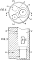
- Figure 4 shows a view of the top end of the lower valve assembly looking downwardly on it.
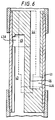
- Body member 41 is provided with fluid passages 42, 43 and 44 bored therein.
- the exterior of the body member 41 is threaded with threads 42 to fit standard tubing collars.
- Passages 43 and 44 are in fluid communication with passages 42 via interior bores 45 and 46.
- Figure 6 is a vertical cross-section along plane C-D (Fig. 4) and
- Figure 5 is a vertical cross-section along diameter A-B of Figure 4.
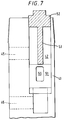
- Figure 7 is a more schematic cross-sectional view of the entire lower valve assembly showing the attachment mechanism for ball and cage valves 50-51 which comprises a compression screw 52 and shaft 53 to press on top of the cage member 51 holding it in place.
- Fluid passage 42 is provided near its lower end with a cage ball valve 50-51. Fluid entering from the hole 44 opening into the tubing string 14 from the top of the lower valve assembly is routed via passage 44 to a point below ball-cage valve 50-51.
- Fluid entering tubing 14 from below the lower valve assembly is routed via bore 43 and opening 45 to a point above the ball-cage valve 50-51 in bore 42.
- water tending to enter tubing string 14 is routed via bore 43 and opening 45 to a point above the ball-cage valve 50-51 such that valve 50-51 seats or closes, preventing this water from entering tubing string 14 any further.
Landscapes
- Engineering & Computer Science (AREA)
- Geology (AREA)
- Life Sciences & Earth Sciences (AREA)
- Mining & Mineral Resources (AREA)
- Fluid Mechanics (AREA)
- Physics & Mathematics (AREA)
- Environmental & Geological Engineering (AREA)
- General Life Sciences & Earth Sciences (AREA)
- Geochemistry & Mineralogy (AREA)
- Oil, Petroleum & Natural Gas (AREA)
- Chemical Kinetics & Catalysis (AREA)
- Chemical & Material Sciences (AREA)
- General Chemical & Material Sciences (AREA)
- Consolidation Of Soil By Introduction Of Solidifying Substances Into Soil (AREA)
- Reciprocating Pumps (AREA)
Applications Claiming Priority (2)
| Application Number | Priority Date | Filing Date | Title |
|---|---|---|---|
| US581864 | 1996-01-02 | ||
| US08/581,864 US6032743A (en) | 1996-01-02 | 1996-01-02 | Method and apparatus for reducing gas well production costs using improved downhole valves |
Publications (2)
| Publication Number | Publication Date |
|---|---|
| EP0783075A2 true EP0783075A2 (de) | 1997-07-09 |
| EP0783075A3 EP0783075A3 (de) | 1998-09-16 |
Family
ID=24326884
Family Applications (1)
| Application Number | Title | Priority Date | Filing Date |
|---|---|---|---|
| EP96309574A Withdrawn EP0783075A3 (de) | 1996-01-02 | 1996-12-31 | Verfahren und Vorrichtung zur Gewinnung von Kohlenwasserstoffen |
Country Status (2)
| Country | Link |
|---|---|
| US (1) | US6032743A (de) |
| EP (1) | EP0783075A3 (de) |
Cited By (2)
| Publication number | Priority date | Publication date | Assignee | Title |
|---|---|---|---|---|
| EP0984134A3 (de) * | 1998-08-18 | 2001-01-31 | Halliburton Energy Services, Inc. | Verfahren und Vorrichtung zur Trennung von Öl und Wasser im Bohrloch während des Pumpens von Erdöl |
| CN106468155A (zh) * | 2015-08-21 | 2017-03-01 | 中国石油化工股份有限公司 | 一种无节流单向注水阀 |
Families Citing this family (5)
| Publication number | Priority date | Publication date | Assignee | Title |
|---|---|---|---|---|
| US6886636B2 (en) * | 1999-05-18 | 2005-05-03 | Down Hole Injection, Inc. | Downhole fluid disposal apparatus and methods |
| US6550535B1 (en) * | 2000-07-20 | 2003-04-22 | Leland Bruce Traylor | Apparatus and method for the downhole gravity separation of water and oil using a single submersible pump and an inline separator containing a control valve |
| US7621339B2 (en) * | 2007-02-14 | 2009-11-24 | Schlumberger Technology Corporation | Downhole production and injection pump system |
| CN105298450B (zh) * | 2015-12-04 | 2018-05-01 | 中国石化江汉油田分公司江汉采油厂 | 一种用于结盐油井的防盐采油一体化生产管柱 |
| CN114482948B (zh) * | 2020-10-27 | 2023-09-26 | 中国石油天然气股份有限公司 | 注水井增注系统 |
Family Cites Families (8)
| Publication number | Priority date | Publication date | Assignee | Title |
|---|---|---|---|---|
| US2281801A (en) * | 1938-12-20 | 1942-05-05 | Joseph H Reynolds | Method of and means for pumping wells |
| US3199592A (en) * | 1963-09-20 | 1965-08-10 | Charles E Jacob | Method and apparatus for producing fresh water or petroleum from underground reservoir formations and to prevent coning |
| US5176216A (en) * | 1991-06-26 | 1993-01-05 | Oxy Usa, Inc. | Bypass seating nipple |
| US5296153A (en) * | 1993-02-03 | 1994-03-22 | Peachey Bruce R | Method and apparatus for reducing the amount of formation water in oil recovered from an oil well |
| US5425416A (en) * | 1994-01-06 | 1995-06-20 | Enviro-Tech Tools, Inc. | Formation injection tool for down-bore in-situ disposal of undesired fluids |
| CA2121179A1 (en) * | 1994-04-13 | 1995-10-14 | Joseph Levesque | Pump for evacuating water from a gas producing well by pumping the water to a lower water absorption zone |
| US5497832A (en) * | 1994-08-05 | 1996-03-12 | Texaco Inc. | Dual action pumping system |
| US5579838A (en) * | 1995-08-07 | 1996-12-03 | Enviro-Tech Tools, Inc. | Above production disposal tool |
-
1996
- 1996-01-02 US US08/581,864 patent/US6032743A/en not_active Expired - Fee Related
- 1996-12-31 EP EP96309574A patent/EP0783075A3/de not_active Withdrawn
Cited By (2)
| Publication number | Priority date | Publication date | Assignee | Title |
|---|---|---|---|---|
| EP0984134A3 (de) * | 1998-08-18 | 2001-01-31 | Halliburton Energy Services, Inc. | Verfahren und Vorrichtung zur Trennung von Öl und Wasser im Bohrloch während des Pumpens von Erdöl |
| CN106468155A (zh) * | 2015-08-21 | 2017-03-01 | 中国石油化工股份有限公司 | 一种无节流单向注水阀 |
Also Published As
| Publication number | Publication date |
|---|---|
| US6032743A (en) | 2000-03-07 |
| EP0783075A3 (de) | 1998-09-16 |
Similar Documents
| Publication | Publication Date | Title |
|---|---|---|
| US5497832A (en) | Dual action pumping system | |
| US8006756B2 (en) | Gas assisted downhole pump | |
| US5765639A (en) | Tubing pump system for pumping well fluids | |
| US8985221B2 (en) | System and method for production of reservoir fluids | |
| US6092600A (en) | Dual injection and lifting system using a rod driven progressive cavity pump and an electrical submersible pump and associate a method | |
| US5425416A (en) | Formation injection tool for down-bore in-situ disposal of undesired fluids | |
| RU2196892C2 (ru) | Устройство и система (варианты) для увеличения добычи жидкости из подземных пластов | |
| US6079491A (en) | Dual injection and lifting system using a rod driven progressive cavity pump and an electrical submersible progressive cavity pump | |
| US6173768B1 (en) | Method and apparatus for downhole oil/water separation during oil well pumping operations | |
| US4490095A (en) | Oilwell pump system and method | |
| US5857519A (en) | Downhole disposal of well produced water using pressurized gas | |
| US6092599A (en) | Downhole oil and water separation system and method | |
| CN101265897B (zh) | 井下采油和注入泵系统 | |
| US6131660A (en) | Dual injection and lifting system using rod pump and an electric submersible pump (ESP) | |
| RU2671370C2 (ru) | Система с переключающим клапаном и способ добычи газа | |
| US10883349B2 (en) | Bottom hole assembly for configuring between artificial lift systems | |
| US6123149A (en) | Dual injection and lifting system using an electrical submersible progressive cavity pump and an electrical submersible pump | |
| WO2011008522A2 (en) | System and method for intermittent gas lift | |
| US6032743A (en) | Method and apparatus for reducing gas well production costs using improved downhole valves | |
| CA2829630A1 (en) | Crossover valve system and method for gas production | |
| US11035200B2 (en) | Downhole formation protection valve | |
| US20170191355A1 (en) | Two-step artificial lift system and method | |
| US20060169458A1 (en) | Pumping system and method for recovering fluid from a well | |
| CA2213631A1 (en) | Method and apparatus for reducing gas well production costs using improved downhole valves | |
| RU2150024C1 (ru) | Насосная установка для добычи нефти из глубоких скважин |
Legal Events
| Date | Code | Title | Description |
|---|---|---|---|
| PUAI | Public reference made under article 153(3) epc to a published international application that has entered the european phase |
Free format text: ORIGINAL CODE: 0009012 |
|
| AK | Designated contracting states |
Kind code of ref document: A2 Designated state(s): DE FR GB |
|
| PUAL | Search report despatched |
Free format text: ORIGINAL CODE: 0009013 |
|
| AK | Designated contracting states |
Kind code of ref document: A3 Designated state(s): DE FR GB |
|
| 17P | Request for examination filed |
Effective date: 19990312 |
|
| 17Q | First examination report despatched |
Effective date: 20020409 |
|
| STAA | Information on the status of an ep patent application or granted ep patent |
Free format text: STATUS: THE APPLICATION IS DEEMED TO BE WITHDRAWN |
|
| 18D | Application deemed to be withdrawn |
Effective date: 20021022 |