EP0783090B1 - Rauchabzugsgerät, insbesondere für Schornsteine und Kamine - Google Patents
Rauchabzugsgerät, insbesondere für Schornsteine und Kamine Download PDFInfo
- Publication number
- EP0783090B1 EP0783090B1 EP96119347A EP96119347A EP0783090B1 EP 0783090 B1 EP0783090 B1 EP 0783090B1 EP 96119347 A EP96119347 A EP 96119347A EP 96119347 A EP96119347 A EP 96119347A EP 0783090 B1 EP0783090 B1 EP 0783090B1
- Authority
- EP
- European Patent Office
- Prior art keywords
- hood
- conveying channels
- flue
- channels
- conveying
- Prior art date
- Legal status (The legal status is an assumption and is not a legal conclusion. Google has not performed a legal analysis and makes no representation as to the accuracy of the status listed.)
- Expired - Lifetime
Links
- 239000003517 fume Substances 0.000 claims abstract description 22
- 230000001747 exhibiting effect Effects 0.000 claims abstract description 4
- 239000012530 fluid Substances 0.000 abstract 1
- 230000000694 effects Effects 0.000 description 4
- 239000000779 smoke Substances 0.000 description 4
- 238000010276 construction Methods 0.000 description 2
- 238000005192 partition Methods 0.000 description 2
- 230000004888 barrier function Effects 0.000 description 1
- 235000013305 food Nutrition 0.000 description 1
- 238000011084 recovery Methods 0.000 description 1
- 238000010992 reflux Methods 0.000 description 1
- 238000009423 ventilation Methods 0.000 description 1
Images


Classifications
-
- F—MECHANICAL ENGINEERING; LIGHTING; HEATING; WEAPONS; BLASTING
- F24—HEATING; RANGES; VENTILATING
- F24B—DOMESTIC STOVES OR RANGES FOR SOLID FUELS; IMPLEMENTS FOR USE IN CONNECTION WITH STOVES OR RANGES
- F24B1/00—Stoves or ranges
- F24B1/18—Stoves with open fires, e.g. fireplaces
- F24B1/183—Stoves with open fires, e.g. fireplaces with additional provisions for heating water
-
- F—MECHANICAL ENGINEERING; LIGHTING; HEATING; WEAPONS; BLASTING
- F24—HEATING; RANGES; VENTILATING
- F24B—DOMESTIC STOVES OR RANGES FOR SOLID FUELS; IMPLEMENTS FOR USE IN CONNECTION WITH STOVES OR RANGES
- F24B1/00—Stoves or ranges
- F24B1/18—Stoves with open fires, e.g. fireplaces
- F24B1/185—Stoves with open fires, e.g. fireplaces with air-handling means, heat exchange means, or additional provisions for convection heating ; Controlling combustion
- F24B1/188—Stoves with open fires, e.g. fireplaces with air-handling means, heat exchange means, or additional provisions for convection heating ; Controlling combustion characterised by use of heat exchange means , e.g. using a particular heat exchange medium, e.g. oil, gas
- F24B1/1885—Stoves with open fires, e.g. fireplaces with air-handling means, heat exchange means, or additional provisions for convection heating ; Controlling combustion characterised by use of heat exchange means , e.g. using a particular heat exchange medium, e.g. oil, gas the heat exchange medium being air only
Definitions
- the present invention relates to a fume-exhausting apparatus, in particular for chimneys and fireplaces, having the features recited in the preamble of claim 1.
- the document FR-A- 2 467 358 teaches to provide, in a chimney comprising a hearth and a hood for collecting fumes to be sent to a flue, a number of channels having lower openings directed downwardly close to the lower inlet mouth of the hood and upper openings directed upwardly and communicating with the lower end of the flue.
- An air stream is drived around the conveying channel and blown into the room, in such a manner to provide a heat recovering from the fumes.
- Document FR-A-2 470 928 which is herein referred as the most relevant state of the art, shows an apparatus comprising a lot of channels having lower openings directed downwardly close to the lower inlet mouth of the hood and upper openings directed upwardly and communicating with the lower end of the flue.
- a waterflow is driven around the conveying channel to recovery heat from the smokes.
- a free space is provided between the bundle of conveying channels and the front side of the hood, to provide a smoke flow directed towards the flue.
- US Patent n. 4,100,913 teaches to provide conveying channels extending from the upper portion of the hood and entering the lower end of the flue. Also in this document the conveying channels are arranged for providing a heat receiving by an air stream passing around the channels itselves.
- US Patent n. 2,277,381 teaches to provide conveying channels extending from the upper portion of the hood and arranged for providing a heat receiving from the fumes, by an air stream blow around the channels itselves.
- the technical task underlying the present invention is to provide a fume-exhausting apparatus, in particular for chimneys and fireplaces, capable of substantially eliminating the above drawbacks.
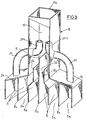
- the fume-exhausting apparatus according to the invention has been generally identified by reference numeral 1.
- the apparatus 1 is adapted to be fitted in a chimney or fireplace of a conventional type known per se comprising a hearth 2, a hood 3 for collecting the fumes produced on the heart, and a flue 4. It comprises a plurality of channels 5 for conveying fumes, located above the hearth 2 and therefore extending within the hood 3.
- the conveying channels 5 exhibit lower openings 5a directed downwardly, disposed close to the lower inlet mouth 3a of the hood 3, and upper openings 5b directed upwardly and disposed close to a lower end 4a of the flue 4, so that they are affected by a draught effect created thereinto.
- the transverse section of the conveying channels 5 has an area corresponding at least to the area of the transverse section of the flue and preferably greater than the latter by 50%.
- the conveying channels 5, for example defined by lengths of rectilinear pipes having a circular section, are disposed in mutual side by side relation to form a bundle and converge close to the upper portion 3b of the hood 3, so that they substantially occupy, at least close to the upper openings thereof 5b, the whole transverse section of the hood 3, apart from the gaps present between the pipes as a result of their circular section.
- one main conveying channel or pipe 5c is provided which is disposed centrally substantially above the flame present in the hearth 2, as well as a plurality of auxiliary conveying channels or pipes 5d disposed perimetrically and each of them having a transverse section the area of which is lower than that of the trasverse section of the main pipe 5c.
- an upper plate-like closing element 6b is also provided which is disposed close to the upper portion 3b of the hood 3.
- the upper plate-like element 6b is also provided with through holes adapted to sealingly engage the upper end portions of the conveying channels 5.
- Suitable air intakes 7 formed in the hood 3 for admitting cold air from the surrounding atmosphere and emitting hot air thereinto enable a forced air circulation to be created, optionally with the aid of ventilation means, which air passing through the gaps present between the conveying channels 5 can be heated by the heat transmitted from the fumes.
- the conveying channels 5 are disposed in mutual side by side relation and in alignment with each other and they occupy the hood volume, and therefore the transverse hood section, only partially.
- the conveying channels 5 in this embodiment exhibit their lower openings 5a disposed in alignment along the front side of the lower inlet mouth 3a of the hood 3 so as to define a suction area extending along the whole extension of said side.
- the conveying channels 5 are integral with each other and consist of a unitary body 8, being divided by partitions 8a.
- Such unitary body 8 can be easily engaged within an already installed hood in order to improve performance of same in drawing fumes.
- the upper openings 5b of the conveying channels 5 defined by the partitions 8a open into an interconnecting pipeline 9 at differentiated heights in order not to hinder the respective smoke flows.
- the upper ends 5b of the conveying channels 5 located at the laterally opposite ends of the unitary body 8 communicate with the upper portion of the interconnecting pipeline 9 by two tubular headers 20 exhibiting end portions 20a adapted to be laterally fitted in the interconnecting pipeline as they bend according to the progress direction of the fumes along said pipeline.
- a draught duct 10 connected in succession to the interconnecting pipeline 9 is a draught duct 10 having an extension enabling one upper end thereof 10a to be directly located in the flue 4.
- the conveying channels 5 enable the whole fume flow to be divided into partial flows, each of which exhibits a reduced vorticity and greater upward kinetic energy.
- the apparatus in question enables the so-called draught effect created within the flue to be moved much closer to the flame or, in other words, to the real fume-producing area, thereby enabling said fumes to be drawn upwardly in a stronger manner.
- the results of said draught effect have been practically zero at distances ranging between 20 and 30 cm from the lower end of the flue itself.
- a suction area extending along the front edge of the hearth is created so as to form a barrier against the emission of fumes towards the room where the fireplace is located.
- the apparatus of the invention makes it possible to intervene on already installed fireplaces with ease, because the apparatus can be readily fitted into a hood and engaged to the front wall thereof. Therefore the apparatus of the invention is capable of making a fireplace flue work properly even if it has an inefficient draught as a result of an imperfect design and/or construction, or at all events is capable of improving performace of a fireplace even under the most unfavourable circumstances.
Landscapes
- Engineering & Computer Science (AREA)
- Chemical & Material Sciences (AREA)
- Combustion & Propulsion (AREA)
- Mechanical Engineering (AREA)
- General Engineering & Computer Science (AREA)
- Incineration Of Waste (AREA)
- Medicines Containing Plant Substances (AREA)
- Respiratory Apparatuses And Protective Means (AREA)
- Ventilation (AREA)
- Exhaust Gas After Treatment (AREA)
- Catalysts (AREA)
- Chemical And Physical Treatments For Wood And The Like (AREA)
- Glass Compositions (AREA)
- Prevention Of Fouling (AREA)
- Waste-Gas Treatment And Other Accessory Devices For Furnaces (AREA)
Claims (8)
- Rauchabzugsvorrichtung, insbesondere für Herde und Kamine, die eine Feuerstelle (2) und eine Haube (3) zum Auffangen des zu einem Rauchabzug(4) zu leitenden Rauchs umfassen,
wobei die Rauchabzugsvorrichtung eine Vielzahl von Rauchleitkanälen (5, 105) umfasst, wobei die Rauchleitkanäle (5, 105) teilweise das Volumen und den Querschnitt der Haube (3) einnehmen und untere, nach unten in Richtung der unteren Haubeneinmündung (3, 103) gerichtete Öffnungen (5a) und obere Öffnungen (5b) aufweisen, die nach oben gerichtet und mit dem unteren Ende des Rauchabzuges verbunden sind, dadurch gekennzeichnet, dass die Rauchleitkanäle (5) die jeweiligen unteren Öffnungen (5a) längs der Vorderseite der unteren Einmündungen (3a) der Haube (3) aneinandergereiht aufweisen. - Vorrichtung nach Anspruch 1, dadurch gekennzeichnet, dass die Rauchleitkanäle (5) durch geradlinige, aneinander gereihte Rohrabschnitte festgelegt sind, die in der Nähe des oberen Teils der Haube (3) zusammenlaufen.
- Vorrichtung nach Anspruch 1, dadurch gekennzeichnet, dass die Rauchleitkanäle (5) insgesamt einen Flächenquerschnitt aufweisen, der mindestens gleich der Fläche des Querschnittes des Rauchkanals (4) sind.
- Vorrichtung nach Anspruch 1, dadurch gekennzeichnet, dass mindestens ein plattenförmiges, unteres Abschlusselement (6a) vorgesehen ist, das sich im Bereich der unteren Einmündung (3a) der Haube (3) erstreckt und Durchgangsbohrungen aufweist, die untere Endabschnitte der Rauchleitkanäle (5) beanspruchen.
- Vorrichtung nach Anspruch 4, dadurch gekennzeichnet, dass sie überdies ein plattenförmiges, oberes Abschlusselement (6b) umfasst, das in der Nähe eines oberen Teils (3b) der Haube (3) angeordnet ist und Durchgangsbohrungen aufweist, die obere Endabschnitte der Rauchleitkanäle (5) beanspruchen, wobei die plattenförmigen unteren (6a) und oberen (6b) Abschlusselemente in Mitwirkung mit der Haube (3) eine Kammer zur Erzeugung von Heißluft festlegen.
- Vorrichtung nach Anspruch 1, dadurch gekennzeichnet, dass die Rauchleitkanäle (5) in einem einzigen, an einer schon installierten Haube (3) in Eingriff bringbaren Körper (8) fest festgelegt, ausgerichtet und angereiht sind.
- Vorrichtung nach Anspruch 6, dadurch gekennzeichnet, dass der einzige Körper (8) ein Übergangsrohr (9) umfasst, in das an verschiedenen Höhen zueinander die oberen Öffnungen (5b) der Rauchleitkanäle (5) einmünden.
- Vorrichtung nach Anspruch 7, bei der nach dem Übergangsrohr ein Zugrohr (10) vorgesehen ist, das ein eigenes oberes, im Rauchrohr (4) angeordnetes Ende (10a) aufweist.
Applications Claiming Priority (5)
| Application Number | Priority Date | Filing Date | Title |
|---|---|---|---|
| ITMI930638A IT1263868B (it) | 1993-03-31 | 1993-03-31 | Dispositivo di recupero calore per camini, caminetti e simili, particolarmente per la generazione di fluidi caldi |
| ITMI930639 | 1993-03-31 | ||
| ITMI930638 | 1993-03-31 | ||
| ITMI930639A IT1263869B (it) | 1993-03-31 | 1993-03-31 | Dispositivo di aspirazione di fumi, particolarmente per camini e caminetti |
| EP94830137A EP0620405B1 (de) | 1993-03-31 | 1994-03-23 | Rauchabzugsgerät insbesondere für Schornsteine und Kamine |
Related Parent Applications (2)
| Application Number | Title | Priority Date | Filing Date |
|---|---|---|---|
| EP94830137A Division EP0620405B1 (de) | 1993-03-31 | 1994-03-23 | Rauchabzugsgerät insbesondere für Schornsteine und Kamine |
| EP94830137.9 Division | 1994-03-23 |
Publications (3)
| Publication Number | Publication Date |
|---|---|
| EP0783090A2 EP0783090A2 (de) | 1997-07-09 |
| EP0783090A3 EP0783090A3 (de) | 1998-12-02 |
| EP0783090B1 true EP0783090B1 (de) | 2000-02-02 |
Family
ID=26330969
Family Applications (2)
| Application Number | Title | Priority Date | Filing Date |
|---|---|---|---|
| EP94830137A Expired - Lifetime EP0620405B1 (de) | 1993-03-31 | 1994-03-23 | Rauchabzugsgerät insbesondere für Schornsteine und Kamine |
| EP96119347A Expired - Lifetime EP0783090B1 (de) | 1993-03-31 | 1994-03-23 | Rauchabzugsgerät, insbesondere für Schornsteine und Kamine |
Family Applications Before (1)
| Application Number | Title | Priority Date | Filing Date |
|---|---|---|---|
| EP94830137A Expired - Lifetime EP0620405B1 (de) | 1993-03-31 | 1994-03-23 | Rauchabzugsgerät insbesondere für Schornsteine und Kamine |
Country Status (4)
| Country | Link |
|---|---|
| EP (2) | EP0620405B1 (de) |
| AT (2) | ATE156581T1 (de) |
| DE (2) | DE69404723T2 (de) |
| DK (1) | DK0620405T3 (de) |
Families Citing this family (3)
| Publication number | Priority date | Publication date | Assignee | Title |
|---|---|---|---|---|
| EP0757208B1 (de) | 1995-07-27 | 1997-03-12 | Gianluca Della Rocca | Vorrichtung zum Verbessern des Zugs, insbesondere für Schornsteine, Kamine oder dergleichen |
| CN104896517B (zh) * | 2015-05-26 | 2017-05-10 | 德清赛众换热器制造有限公司 | 一种生物燃料壁炉 |
| CN108444106A (zh) * | 2018-04-25 | 2018-08-24 | 大连恒通和科技有限公司 | 锅炉用冷凝系统 |
Family Cites Families (6)
| Publication number | Priority date | Publication date | Assignee | Title |
|---|---|---|---|---|
| US2277381A (en) * | 1940-06-10 | 1942-03-24 | Murray J Black | Heating system |
| US4100913A (en) | 1974-10-29 | 1978-07-18 | Armstrong Ernest Deloy | Fireplace heating system |
| FR2294403A1 (fr) * | 1974-12-12 | 1976-07-09 | Lambert Jean | Atre-chaudiere combinant le chauffage au bois et la ventilation mecanique controlee double flux |
| FR2467358A1 (fr) | 1979-10-11 | 1981-04-17 | Jost Edouard | Dispositif de recuperation de chaleur pour cheminees a feu ouvert et poeles a bois |
| FR2470928A1 (fr) * | 1979-12-04 | 1981-06-12 | Bonnin Jean Pierre | Cheminee d'agrement et de chauffage central |
| FR2510725A1 (fr) * | 1981-02-26 | 1983-02-04 | Vergnes Jacques | Dispositif pour recuperer la chaleur notamment dans un atre |
-
1994
- 1994-03-23 DE DE69404723T patent/DE69404723T2/de not_active Expired - Fee Related
- 1994-03-23 EP EP94830137A patent/EP0620405B1/de not_active Expired - Lifetime
- 1994-03-23 DK DK94830137.9T patent/DK0620405T3/da active
- 1994-03-23 AT AT94830137T patent/ATE156581T1/de not_active IP Right Cessation
- 1994-03-23 AT AT96119347T patent/ATE189514T1/de not_active IP Right Cessation
- 1994-03-23 EP EP96119347A patent/EP0783090B1/de not_active Expired - Lifetime
- 1994-03-23 DE DE69422934T patent/DE69422934T2/de not_active Expired - Fee Related
Also Published As
| Publication number | Publication date |
|---|---|
| EP0783090A2 (de) | 1997-07-09 |
| DE69422934T2 (de) | 2000-08-17 |
| EP0620405A1 (de) | 1994-10-19 |
| DE69404723T2 (de) | 1998-02-05 |
| ATE189514T1 (de) | 2000-02-15 |
| EP0783090A3 (de) | 1998-12-02 |
| DE69404723D1 (de) | 1997-09-11 |
| ATE156581T1 (de) | 1997-08-15 |
| EP0620405B1 (de) | 1997-08-06 |
| DK0620405T3 (da) | 1998-02-23 |
| DE69422934D1 (de) | 2000-03-09 |
Similar Documents
| Publication | Publication Date | Title |
|---|---|---|
| CA1283010C (en) | Wind-resistant outdoor heating appliance | |
| US6000391A (en) | Positive air flow ventilation system | |
| CA2351795A1 (en) | Ventilation system and method | |
| CA2013250A1 (en) | High-efficiency furnace for mobile homes | |
| EP0783090B1 (de) | Rauchabzugsgerät, insbesondere für Schornsteine und Kamine | |
| US5158069A (en) | Wind-resistant heating appliance | |
| US3965886A (en) | Home fireplace heating | |
| US4827900A (en) | Stove with external tubes for increasing heat dissipation | |
| US4047490A (en) | Recuperative heating system | |
| US4325430A (en) | Heat recapture device | |
| US4079888A (en) | Heat recovery system for forced air furnaces | |
| EP0530126B1 (de) | Ofen für Holz mit Glasteil und Mittel zu seiner Reinigung | |
| EP0757208B1 (de) | Vorrichtung zum Verbessern des Zugs, insbesondere für Schornsteine, Kamine oder dergleichen | |
| EP0939280A3 (de) | Wärmespeicherkamin | |
| EP0027478A1 (de) | Wärmetauscher zur Wärmerückgewinnung aus Abgasen | |
| JP3004194U (ja) | ジェットによる排気煙筒 | |
| US4685441A (en) | Heat exchanger | |
| US3168861A (en) | Venting devices | |
| CN211119426U (zh) | 一种伸缩式吹灰枪 | |
| EP1134532A1 (de) | Kamin mit Wärmetauscher zur Raumbeheizung | |
| CA2494239A1 (en) | Ventilation system and method | |
| WO2022167050A1 (en) | Method for emiting flue gas and building for such method | |
| EP0668472A1 (de) | Kaminanlage | |
| DE24239C (de) | Ofen rohrfutter für Zimmerlüftung | |
| CN2237800Y (zh) | 排烟弯头 |
Legal Events
| Date | Code | Title | Description |
|---|---|---|---|
| PUAI | Public reference made under article 153(3) epc to a published international application that has entered the european phase |
Free format text: ORIGINAL CODE: 0009012 |
|
| AC | Divisional application: reference to earlier application |
Ref document number: 620405 Country of ref document: EP |
|
| AK | Designated contracting states |
Kind code of ref document: A2 Designated state(s): AT BE CH DE DK FR GB IE LI LU NL SE |
|
| PUAL | Search report despatched |
Free format text: ORIGINAL CODE: 0009013 |
|
| AK | Designated contracting states |
Kind code of ref document: A3 Designated state(s): AT BE CH DE DK FR GB IE LI LU NL SE |
|
| 17P | Request for examination filed |
Effective date: 19981102 |
|
| 17Q | First examination report despatched |
Effective date: 19990215 |
|
| GRAG | Despatch of communication of intention to grant |
Free format text: ORIGINAL CODE: EPIDOS AGRA |
|
| GRAG | Despatch of communication of intention to grant |
Free format text: ORIGINAL CODE: EPIDOS AGRA |
|
| GRAH | Despatch of communication of intention to grant a patent |
Free format text: ORIGINAL CODE: EPIDOS IGRA |
|
| GRAH | Despatch of communication of intention to grant a patent |
Free format text: ORIGINAL CODE: EPIDOS IGRA |
|
| GRAA | (expected) grant |
Free format text: ORIGINAL CODE: 0009210 |
|
| AC | Divisional application: reference to earlier application |
Ref document number: 620405 Country of ref document: EP |
|
| AK | Designated contracting states |
Kind code of ref document: B1 Designated state(s): AT BE CH DE DK FR GB IE LI LU NL SE |
|
| PG25 | Lapsed in a contracting state [announced via postgrant information from national office to epo] |
Ref country code: NL Free format text: LAPSE BECAUSE OF FAILURE TO SUBMIT A TRANSLATION OF THE DESCRIPTION OR TO PAY THE FEE WITHIN THE PRESCRIBED TIME-LIMIT Effective date: 20000202 Ref country code: BE Free format text: LAPSE BECAUSE OF FAILURE TO SUBMIT A TRANSLATION OF THE DESCRIPTION OR TO PAY THE FEE WITHIN THE PRESCRIBED TIME-LIMIT Effective date: 20000202 |
|
| REF | Corresponds to: |
Ref document number: 189514 Country of ref document: AT Date of ref document: 20000215 Kind code of ref document: T |
|
| REG | Reference to a national code |
Ref country code: CH Ref legal event code: EP |
|
| REF | Corresponds to: |
Ref document number: 69422934 Country of ref document: DE Date of ref document: 20000309 |
|
| PG25 | Lapsed in a contracting state [announced via postgrant information from national office to epo] |
Ref country code: LU Free format text: LAPSE BECAUSE OF NON-PAYMENT OF DUE FEES Effective date: 20000323 Ref country code: IE Free format text: LAPSE BECAUSE OF NON-PAYMENT OF DUE FEES Effective date: 20000323 |
|
| PG25 | Lapsed in a contracting state [announced via postgrant information from national office to epo] |
Ref country code: SE Free format text: LAPSE BECAUSE OF FAILURE TO SUBMIT A TRANSLATION OF THE DESCRIPTION OR TO PAY THE FEE WITHIN THE PRESCRIBED TIME-LIMIT Effective date: 20000502 Ref country code: GB Free format text: LAPSE BECAUSE OF NON-PAYMENT OF DUE FEES Effective date: 20000502 Ref country code: DK Free format text: LAPSE BECAUSE OF FAILURE TO SUBMIT A TRANSLATION OF THE DESCRIPTION OR TO PAY THE FEE WITHIN THE PRESCRIBED TIME-LIMIT Effective date: 20000502 |
|
| REG | Reference to a national code |
Ref country code: IE Ref legal event code: FG4D |
|
| REG | Reference to a national code |
Ref country code: CH Ref legal event code: NV Representative=s name: ISLER & PEDRAZZINI AG |
|
| ET | Fr: translation filed | ||
| NLV1 | Nl: lapsed or annulled due to failure to fulfill the requirements of art. 29p and 29m of the patents act | ||
| PLBE | No opposition filed within time limit |
Free format text: ORIGINAL CODE: 0009261 |
|
| STAA | Information on the status of an ep patent application or granted ep patent |
Free format text: STATUS: NO OPPOSITION FILED WITHIN TIME LIMIT |
|
| GBPC | Gb: european patent ceased through non-payment of renewal fee |
Effective date: 20000502 |
|
| 26N | No opposition filed | ||
| REG | Reference to a national code |
Ref country code: IE Ref legal event code: MM4A |
|
| PGFP | Annual fee paid to national office [announced via postgrant information from national office to epo] |
Ref country code: DE Payment date: 20020404 Year of fee payment: 9 |
|
| PGFP | Annual fee paid to national office [announced via postgrant information from national office to epo] |
Ref country code: FR Payment date: 20020410 Year of fee payment: 9 |
|
| PGFP | Annual fee paid to national office [announced via postgrant information from national office to epo] |
Ref country code: AT Payment date: 20020411 Year of fee payment: 9 |
|
| PGFP | Annual fee paid to national office [announced via postgrant information from national office to epo] |
Ref country code: CH Payment date: 20020412 Year of fee payment: 9 |
|
| PG25 | Lapsed in a contracting state [announced via postgrant information from national office to epo] |
Ref country code: AT Free format text: LAPSE BECAUSE OF NON-PAYMENT OF DUE FEES Effective date: 20030323 |
|
| PG25 | Lapsed in a contracting state [announced via postgrant information from national office to epo] |
Ref country code: LI Free format text: LAPSE BECAUSE OF NON-PAYMENT OF DUE FEES Effective date: 20030331 Ref country code: CH Free format text: LAPSE BECAUSE OF NON-PAYMENT OF DUE FEES Effective date: 20030331 |
|
| PG25 | Lapsed in a contracting state [announced via postgrant information from national office to epo] |
Ref country code: DE Free format text: LAPSE BECAUSE OF NON-PAYMENT OF DUE FEES Effective date: 20031001 |
|
| REG | Reference to a national code |
Ref country code: CH Ref legal event code: PL |
|
| PG25 | Lapsed in a contracting state [announced via postgrant information from national office to epo] |
Ref country code: FR Free format text: LAPSE BECAUSE OF NON-PAYMENT OF DUE FEES Effective date: 20031127 |
|
| REG | Reference to a national code |
Ref country code: FR Ref legal event code: ST |