EP0783120A2 - Plateforme stabilisée pour laser et module d'interface - Google Patents
Plateforme stabilisée pour laser et module d'interface Download PDFInfo
- Publication number
- EP0783120A2 EP0783120A2 EP97300008A EP97300008A EP0783120A2 EP 0783120 A2 EP0783120 A2 EP 0783120A2 EP 97300008 A EP97300008 A EP 97300008A EP 97300008 A EP97300008 A EP 97300008A EP 0783120 A2 EP0783120 A2 EP 0783120A2
- Authority
- EP
- European Patent Office
- Prior art keywords
- support structure
- platform
- laser
- laser system
- mount
- Prior art date
- Legal status (The legal status is an assumption and is not a legal conclusion. Google has not performed a legal analysis and makes no representation as to the accuracy of the status listed.)
- Withdrawn
Links
Images


Classifications
-
- H—ELECTRICITY
- H01—ELECTRIC ELEMENTS
- H01S—DEVICES USING THE PROCESS OF LIGHT AMPLIFICATION BY STIMULATED EMISSION OF RADIATION [LASER] TO AMPLIFY OR GENERATE LIGHT; DEVICES USING STIMULATED EMISSION OF ELECTROMAGNETIC RADIATION IN WAVE RANGES OTHER THAN OPTICAL
- H01S3/00—Lasers, i.e. devices using stimulated emission of electromagnetic radiation in the infrared, visible or ultraviolet wave range
- H01S3/02—Constructional details
-
- H—ELECTRICITY
- H10—SEMICONDUCTOR DEVICES; ELECTRIC SOLID-STATE DEVICES NOT OTHERWISE PROVIDED FOR
- H10W—GENERIC PACKAGES, INTERCONNECTIONS, CONNECTORS OR OTHER CONSTRUCTIONAL DETAILS OF DEVICES COVERED BY CLASS H10
- H10W99/00—Subject matter not provided for in other groups of this subclass
-
- G—PHYSICS
- G02—OPTICS
- G02B—OPTICAL ELEMENTS, SYSTEMS OR APPARATUS
- G02B7/00—Mountings, adjusting means, or light-tight connections, for optical elements
-
- H—ELECTRICITY
- H01—ELECTRIC ELEMENTS
- H01S—DEVICES USING THE PROCESS OF LIGHT AMPLIFICATION BY STIMULATED EMISSION OF RADIATION [LASER] TO AMPLIFY OR GENERATE LIGHT; DEVICES USING STIMULATED EMISSION OF ELECTROMAGNETIC RADIATION IN WAVE RANGES OTHER THAN OPTICAL
- H01S3/00—Lasers, i.e. devices using stimulated emission of electromagnetic radiation in the infrared, visible or ultraviolet wave range
- H01S3/14—Lasers, i.e. devices using stimulated emission of electromagnetic radiation in the infrared, visible or ultraviolet wave range characterised by the material used as the active medium
- H01S3/22—Gases
- H01S3/223—Gases the active gas being polyatomic, i.e. containing two or more atoms
- H01S3/225—Gases the active gas being polyatomic, i.e. containing two or more atoms comprising an excimer or exciplex
Definitions
- This invention relates to apparatus used to provide stable operating platforms for sensitive instrumentation and particularly to a stable mounting platform for laser systems and their accompanying optical interface components, while additionally facilitating a modular, compartmentalized design for serviceability and safety.
- the speed of today's high-speed performance digital computers is dependent both on the speed of the IC chip and the compactness of the package on which the chip is mounted.
- the package connects the signals between the chips, provides power and cooling capability, as well as providing interconnects to other parts of the computer.
- the packaging circuits By making the packaging circuits smaller, the signals have less distance to travel which translates into reduced processing time. As circuits get smaller, the way they are fabricated and the accuracy with which they have to be positioned becomes more challenging.
- Micro lithography for advanced ULSI fabrication is currently making a transition from using an i-line (365nm) mercury lamp to a deep-UV excimer laser, primarily krypton fluoride (KrF), having a wavelength of 248nm, as the illumination source.
- KrF krypton fluoride
- the KrF excimer laser is expected to become the primary exposure tool for printing sub-0.4 ⁇ m design rule features in IC manufacturing, while Argon fluoride (ArF) with its 193nm wavelength, is expected for use in sub-0.25 ⁇ m design features.
- ArF Argon fluoride
- wafer steppers utilize precision positioning tables with interferometers and CCD optical recognition to provide accurate placement of design patterns in silicon wafers.
- the wafer is generally automatically loaded from a cassette into a wafer holder where it is automatically leveled, focused, and aligned to the mask.
- Each pattern on the part has to be overlaid with a defined accuracy on a previously-defined pattern.
- One pattern may be used as the mask for each part, wherein the excimer laser acts as a projection ablation tool to form the vias which interconnect the wiring levels of the circuit.
- the mask is changed as the step-and-repeat process continues. These vias must be placed precisely on the features defined at the previous level, making the accuracy of the laser system critical.
- This accuracy can be affected by lens distortion, tool-to-tool errors, and particularly by alignment mark errors. Because of the increasingly smaller design rule features being required in the industry, changes in beam profile and direction cannot be tolerated as the result of misalignment or external forces acting to destabilize the alignment accuracy of the laser-stepper system.
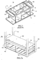
- FIG. 1 an example of a laser system support structure 10 of conventional design is shown, having a horizontal support frame 20 and rail cross members 30.
- the optical platform (not shown) and the laser system components mounted thereon are typically mounted on rail cross members 30 and supported equally by internal panel 35 and vertical frame members 40, which are tied into support frame 20 by brackets 45, shown in the closeup labeled A.
- Beam delivery interface mount 50 used to couple and hold the laser system to the wafer stepper's beam delivery equipment in a precise and stable manner, is generally mounted to frame 20 since, in this conventional design, this member is the most robust and will provide the most rigid support.
- An object to the present invention is to provide a support structure design in which the optical platform is a primary and independent structural element of the laser frame, and the beam delivery interface is an integral component of the optical platform.
- each attachment point is a swivel joint to prevent bending of the platform.
- the objects and features of one aspect of the present invention are realized by the use of an independent support platform for the laser's chamber and optical system.
- the support platform is swivel-mounted to the laser's support frame by a ball-cup joint at only three attachment points at the base of the laser support frame.
- Each of the attachment points are threaded to allow the support platform surface to be adjusted to a measured level orientation once the chamber and optical systems are mounted.
- the use of only three attachment points provides a three point kinematic mount that ensures that the support platform will not undergo a deformation if the laser's support frame is subjected to an outside force. Instead, the entire platform will move, and because the optical system and the beam delivery interface are integral to the support platform, they will likewise move in the swivel joints an equal amount maintaining a level orientation, thereby maintaining the optical alignment.
- Another aspect of the invention resulting from the use of an independent platform for the laser's chamber and optical system is the use of modular-subsystems and overall compartmentalization of these subsystems into three horizontal levels: utility, chamber/optics and electrical; thereby facilitating safety and maintenance by segregating the cooling subsystems from high voltage areas and allowing all servicing tasks to be performed from the front side alone via extension rails and hinged mounts to allow easy access to each of the laser's subsystem modules.
- FIG. 1 depicts a laser frame and optical support arrangement of conventional design, well-known in the prior art.
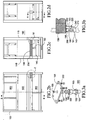
- FIG. 2a depicts the optical platform of the present invention incorporated in a laser frame support structure.
- FIG. 2b depicts a front view of a laser support frame incorporating the optical platform of the present invention.
- FIG. 2c depicts a first end view of the laser support frame shown in FIG. 2b along section line B-B.
- FIG. 2d depicts a second end view of the laser support frame shown in FIG. 2b.
- FIG. 3a depicts an exploded view of the ball-cup joint arrangement used at each of the three optical platform-laser support frame attachment points.
- FIG. 3b depicts a cut-away view of the ball-cup attachment to the laser support frame along section lines A-A of FIG. 2d.
- FIG. 4 depicts the optical platform of the present invention isolated from the laser support frame, showing the laser's optical system and chamber mounted thereon.
- FIG. 5a depicts the laser frame of the present invention, having a compartmentalized, slide-modular subsystem design.
- FIG. 5b depicts a representative modular subsystem having the sliding-hinge feature of the present invention.
- a laser support frame 100 is shown having vertical frame support members 110 and rear vertical frame support members 115, along with a frame support base 120. Internal base support members 130 are also shown and are recognized by those skilled in the art as necessary to provide structural integrity to support base 120.
- Horizontal brace member 140 is rigidly mounted between vertical frame support members 110 and 115 and provides support for chamber/optics platform 150.
- Chamber/optics platform 150 is designed to provide a rigid, stable base support for the laser chamber and optics modules and is preferably constructed utilizing a stainless steel honeycomb internal structure sandwiched between stainless steel plates to minimize overall system weight and still provide required rigidity. However, as those skilled in the art will recognize, platform 150 may be constructed of any material sufficient to provide the operational rigidity required.
- chamber/optics platform 150 is shown detached from laser support frame 100 of FIG. 2a, having laser chamber 160, mounted on support rails 165 to allow the chamber to be laterally rolled to facilitate maintenance, and optics modules 170 mounted on bracket 173.
- Support rails 165 preferably incorporate a rail extender mechanism (not shown), such a those well known in the art, and similar in design to the module slides described infra, to allow laser chamber 160 to be extended beyond the outer perimeter of support frame 100, out of axial alignment with optics module 170, as shown by extension lines 167, to provide easy access to the optics module and other chamber interface components.
- Chamber/optics platform 150 is securely attached to horizontal brace 140 in a three point kinematic mount shown in FIG. 2b and 2d by a ball-cup joint 190 at each of the three points.
- chamber/optics platform 150 was previously described herein as being preferably constructed from a stainless steel honeycomb structure sandwiched between stainless steel plates to minimize weight and still provide the required platform rigidity. Even with the platform's weight minimized, the loading of the laser's chamber and optics components provides the platform with sufficient mass to render insignificant the constraints on the linear degeees of freedom imposed by the ball-cup type joint.
- the second and third mounts could incorporate a cup and roller combination or a "V" groove to allow movement along the line segments which define the isosceles triangle created by the attachment points.
- these alternative mounts are only two examples of attachment methods which would allow the chamber/optics platform to move along the required degrees of freedom in reaction to thermal or other forces, and that other equivalent arrangements are available.
- ball-cup joint 190 is shown as an exploded close-up, comprising a threaded shaft 191 leveling means, and locking device comprising a washer 192 and jam nut 193 threaded onto shaft 191.
- Cup element 194 is mounted on floating pin 195 housed in cup housing 196.
- Washer 197 is mounted inside cup element 194 atop floating pin 195 to provide support for the cup element when cup housing 196 and pin engagement screw 199 are threaded into engagement with flange 198 and floating pin 195 respectively.
- Bolts 200 secure flange 198 to the underside of chamber/optics platform 150 (not shown).
- FIG. 3b showing ball-cup joint mounting along section lines A-A of FIG. 2d, depicts threaded shaft 191 of ball-cup joint 190 in threaded engagement with horizontal support 140 and flange 198 coupled to chamber/optics platforms 150 by bolts 200.
- secondary support brace 210 Coupled to the interior side of horizontal support 140, and paired with each ball-cup joint 190 at each of the three positions, is secondary support brace 210, having a load bearing face 220 coupled to chamber/optics platform 150 via tension rod 230.
- chamber/optics platform 150 is adjusted to a level position via threaded shaft 191 on each of the three ball-cup attachment points, and tension rod 230 is then secured into spring biased engagement with load bearing face 220 by support nut 240 having a spring washer (not shown) to maintain rod 230 in tension and provide enhanced stability to the chamber/optics platform.
- This arrangement acts to prevent platform 150 from liting out of the ball-cup attachment by use of tension rod 230, while also absorbing vibrational and other farces via the spring washer.
- two of the three ball-cup joint/secondary support brace mount pairs are positioned under the beam output end of chamber/optics platform 150 in an isosceles configuration to provide additional support for beam delivery interface mount 180 and the increased load resulting from the coupling of the laser system to the beam delivery equipment of the stepper.
- FIG. 2c a first end view of laser support frame 100 across section B-B of FIG. 2b is shown, wherein the third of the thee-point independent support feature of optics platform 150 is represented.
- Ball-cup joint 190 is attached to horizontal support 140 as previously described, providing the only attachment points between support frame 100 and chamber/optics platform 150.
- Frame divider channel 250 provides structural support for laser frame 100, being positioned on each side of chamber/optics platform 150, coupling together respectively front vertical frame supports 110 and rear vertical frame supports 115. This arrangement allows a maintaining of the structural integrity of laser frame 100 while, at the same time, segregating chamber/optics platform 150 as shown in highlighted section W.
- the laser support frame can be subjected to external force loads, as previously described in the prior art design of FIG. 1, and still maintain alignment precision.
- support frame 100 will deflect in the same manner as the prior art design; however, because chamber/optics platform 150 is independently supported by ball-cup joints 190, the ball-cup socket will rotate in response to the frame deflection while chamber/optics platform 150 remains undeformed.
- laser chamber 160, optics module 170, and the externally coupled beam delivery equipment, via beam delivery interface mount 180 are all maintained in stasis with beam alignment precision preserved.
- a secondary advantage of the platform of the present design is the modular design and compartmentalization of laser subsystems into three horizontal levels.
- the upper level 300 is dedicated to hold all high voltage/electric sub-components such as the pulse power module (not shown), while the lower level 400 is dedicated to utility subsystems such as water cooling and gas distribution modules (not shown).
- middle level 500 is dedicated to the chamber and optics components and is supported by the swivel mount thee-point support platform specifically described above.
- This modular and compartmentalized design provides two distinct advantages; the first being the safety feature of separating the water coolant systems from the high voltage areas; and the second being the ability to service the laser from the front side only, thereby allowing permanent panels (not shown) to be fitted for enclosing laser frame 100 on all other sides.
- the modular sub-components for each level are mounted on slides 600, such as those generally available from companies such as General Devices, Jonathan and others.
- slides 600 such as those generally available from companies such as General Devices, Jonathan and others.
- the operation and installation of slides of this type are well known, with the fixed portion being mounted to the laser frame via horizontal support plates, such as plate 610, and the moving (slide) portion 620 being affixed to the laser module to allow the specific module to be laterally repositioned clear of frame 100 to allow easy access to all components. In this way, all servicing can be conducted from the front of the laser, with access available to all module surfaces.
- FIG. 5b the preferred embodiment wherein module 630 itself would be attached to the slide element 620 by a locking hinge 640.
- This locking hinge feature enhances the ability to easily service the module by allowing the module to pivot by rotating in a downward direction (as shown) about the hinge to gain easy access to the rear portion of the module and lock in various angular positions (i.e., 45°, 60°, 90°).
Landscapes
- Physics & Mathematics (AREA)
- Electromagnetism (AREA)
- Optics & Photonics (AREA)
- Engineering & Computer Science (AREA)
- Plasma & Fusion (AREA)
- General Physics & Mathematics (AREA)
- Lasers (AREA)
- Exposure And Positioning Against Photoresist Photosensitive Materials (AREA)
- Details Of Measuring And Other Instruments (AREA)
Applications Claiming Priority (2)
| Application Number | Priority Date | Filing Date | Title |
|---|---|---|---|
| US583380 | 1984-02-24 | ||
| US08/583,380 US5863017A (en) | 1996-01-05 | 1996-01-05 | Stabilized laser platform and module interface |
Publications (2)
| Publication Number | Publication Date |
|---|---|
| EP0783120A2 true EP0783120A2 (fr) | 1997-07-09 |
| EP0783120A3 EP0783120A3 (fr) | 1997-10-15 |
Family
ID=24332882
Family Applications (1)
| Application Number | Title | Priority Date | Filing Date |
|---|---|---|---|
| EP97300008A Withdrawn EP0783120A3 (fr) | 1996-01-05 | 1997-01-02 | Plateforme stabilisée pour laser et module d'interface |
Country Status (5)
| Country | Link |
|---|---|
| US (1) | US5863017A (fr) |
| EP (1) | EP0783120A3 (fr) |
| JP (1) | JP2983483B2 (fr) |
| KR (1) | KR100262255B1 (fr) |
| CA (1) | CA2194333A1 (fr) |
Cited By (3)
| Publication number | Priority date | Publication date | Assignee | Title |
|---|---|---|---|---|
| WO2000040069A1 (fr) * | 1998-12-29 | 2000-07-06 | Koninklijke Philips Electronics N.V. | Machine de placement de composants |
| EP0994541A3 (fr) * | 1998-10-16 | 2002-09-25 | Cymer, Inc. | Structure de support pour la chambre et l'optique d'un laser à gaz |
| WO2013144693A3 (fr) * | 2012-03-29 | 2013-12-05 | Gigaphoton Inc. | Appareil laser et son procédé de fabrication |
Families Citing this family (90)
| Publication number | Priority date | Publication date | Assignee | Title |
|---|---|---|---|---|
| US6926487B1 (en) * | 1998-04-28 | 2005-08-09 | Rexam Ab | Method and apparatus for manufacturing marked articles to be included in cans |
| US20020127497A1 (en) * | 1998-09-10 | 2002-09-12 | Brown Daniel J. W. | Large diffraction grating for gas discharge laser |
| US6567450B2 (en) | 1999-12-10 | 2003-05-20 | Cymer, Inc. | Very narrow band, two chamber, high rep rate gas discharge laser system |
| US6095482A (en) * | 1998-09-14 | 2000-08-01 | Lucent Technologies, Inc. | Universal equipment mounting structure and method of using |
| US6288358B1 (en) * | 1998-12-15 | 2001-09-11 | Lsp Technologies, Inc. | Mobile laser peening system |
| US6801560B2 (en) * | 1999-05-10 | 2004-10-05 | Cymer, Inc. | Line selected F2 two chamber laser system |
| US6865210B2 (en) * | 2001-05-03 | 2005-03-08 | Cymer, Inc. | Timing control for two-chamber gas discharge laser system |
| US7856044B2 (en) * | 1999-05-10 | 2010-12-21 | Cymer, Inc. | Extendable electrode for gas discharge laser |
| US6455806B1 (en) * | 2000-01-14 | 2002-09-24 | Rexam Ab | Arrangement for shaping and marking a target |
| US6904073B2 (en) * | 2001-01-29 | 2005-06-07 | Cymer, Inc. | High power deep ultraviolet laser with long life optics |
| US7180081B2 (en) * | 2000-06-09 | 2007-02-20 | Cymer, Inc. | Discharge produced plasma EUV light source |
| US6693939B2 (en) | 2001-01-29 | 2004-02-17 | Cymer, Inc. | Laser lithography light source with beam delivery |
| US6425559B1 (en) | 2000-09-29 | 2002-07-30 | Cymer, Inc. | Gas laser chamber with vertical vibration isolator |
| US6912052B2 (en) * | 2000-11-17 | 2005-06-28 | Cymer, Inc. | Gas discharge MOPA laser spectral analysis module |
| US6839372B2 (en) * | 2000-11-17 | 2005-01-04 | Cymer, Inc. | Gas discharge ultraviolet laser with enclosed beam path with added oxidizer |
| US7190707B2 (en) * | 2001-01-29 | 2007-03-13 | Cymer, Inc. | Gas discharge laser light source beam delivery unit |
| US20050025882A1 (en) * | 2001-01-29 | 2005-02-03 | Partlo William N. | Optical elements with protective undercoating |
| US6704339B2 (en) | 2001-01-29 | 2004-03-09 | Cymer, Inc. | Lithography laser with beam delivery and beam pointing control |
| US6704340B2 (en) | 2001-01-29 | 2004-03-09 | Cymer, Inc. | Lithography laser system with in-place alignment tool |
| JP2002289497A (ja) * | 2001-03-23 | 2002-10-04 | Tokyo Electron Ltd | 半導体製造設備及び半導体製造方法 |
| US7230964B2 (en) * | 2001-04-09 | 2007-06-12 | Cymer, Inc. | Lithography laser with beam delivery and beam pointing control |
| US6690704B2 (en) | 2001-04-09 | 2004-02-10 | Cymer, Inc. | Control system for a two chamber gas discharge laser |
| US7079564B2 (en) * | 2001-04-09 | 2006-07-18 | Cymer, Inc. | Control system for a two chamber gas discharge laser |
| US7039086B2 (en) * | 2001-04-09 | 2006-05-02 | Cymer, Inc. | Control system for a two chamber gas discharge laser |
| US7009140B2 (en) * | 2001-04-18 | 2006-03-07 | Cymer, Inc. | Laser thin film poly-silicon annealing optical system |
| US7061959B2 (en) * | 2001-04-18 | 2006-06-13 | Tcz Gmbh | Laser thin film poly-silicon annealing system |
| US7167499B2 (en) * | 2001-04-18 | 2007-01-23 | Tcz Pte. Ltd. | Very high energy, high stability gas discharge laser surface treatment system |
| US20050259709A1 (en) | 2002-05-07 | 2005-11-24 | Cymer, Inc. | Systems and methods for implementing an interaction between a laser shaped as a line beam and a film deposited on a substrate |
| US7372056B2 (en) * | 2005-06-29 | 2008-05-13 | Cymer, Inc. | LPP EUV plasma source material target delivery system |
| US7378673B2 (en) * | 2005-02-25 | 2008-05-27 | Cymer, Inc. | Source material dispenser for EUV light source |
| US7439530B2 (en) * | 2005-06-29 | 2008-10-21 | Cymer, Inc. | LPP EUV light source drive laser system |
| US7465946B2 (en) * | 2004-03-10 | 2008-12-16 | Cymer, Inc. | Alternative fuels for EUV light source |
| US6928093B2 (en) * | 2002-05-07 | 2005-08-09 | Cymer, Inc. | Long delay and high TIS pulse stretcher |
| US7598509B2 (en) * | 2004-11-01 | 2009-10-06 | Cymer, Inc. | Laser produced plasma EUV light source |
| US7088758B2 (en) | 2001-07-27 | 2006-08-08 | Cymer, Inc. | Relax gas discharge laser lithography light source |
| US7830934B2 (en) * | 2001-08-29 | 2010-11-09 | Cymer, Inc. | Multi-chamber gas discharge laser bandwidth control through discharge timing |
| US6963595B2 (en) * | 2001-08-29 | 2005-11-08 | Cymer, Inc. | Automatic gas control system for a gas discharge laser |
| US20050100072A1 (en) * | 2001-11-14 | 2005-05-12 | Rao Rajasekhar M. | High power laser output beam energy density reduction |
| US7671349B2 (en) * | 2003-04-08 | 2010-03-02 | Cymer, Inc. | Laser produced plasma EUV light source |
| US6798812B2 (en) | 2002-01-23 | 2004-09-28 | Cymer, Inc. | Two chamber F2 laser system with F2 pressure based line selection |
| US7016388B2 (en) * | 2002-05-07 | 2006-03-21 | Cymer, Inc. | Laser lithography light source with beam delivery |
| US7741639B2 (en) * | 2003-01-31 | 2010-06-22 | Cymer, Inc. | Multi-chambered excimer or molecular fluorine gas discharge laser fluorine injection control |
| US7217941B2 (en) * | 2003-04-08 | 2007-05-15 | Cymer, Inc. | Systems and methods for deflecting plasma-generated ions to prevent the ions from reaching an internal component of an EUV light source |
| US7277188B2 (en) | 2003-04-29 | 2007-10-02 | Cymer, Inc. | Systems and methods for implementing an interaction between a laser shaped as a line beam and a film deposited on a substrate |
| US7209507B2 (en) * | 2003-07-30 | 2007-04-24 | Cymer, Inc. | Method and apparatus for controlling the output of a gas discharge MOPA laser system |
| US6894785B2 (en) * | 2003-09-30 | 2005-05-17 | Cymer, Inc. | Gas discharge MOPA laser spectral analysis module |
| US6873418B1 (en) | 2003-09-30 | 2005-03-29 | Cymer, Inc. | Optical mountings for gas discharge MOPA laser spectral analysis module |
| US7277464B2 (en) * | 2003-12-18 | 2007-10-02 | Cymer, Inc. | Method and apparatus for controlling the output of a gas discharge laser system |
| US20060146906A1 (en) * | 2004-02-18 | 2006-07-06 | Cymer, Inc. | LLP EUV drive laser |
| US7196342B2 (en) * | 2004-03-10 | 2007-03-27 | Cymer, Inc. | Systems and methods for reducing the influence of plasma-generated debris on the internal components of an EUV light source |
| US7522650B2 (en) * | 2004-03-31 | 2009-04-21 | Cymer, Inc. | Gas discharge laser chamber improvements |
| US7006547B2 (en) * | 2004-03-31 | 2006-02-28 | Cymer, Inc. | Very high repetition rate narrow band gas discharge laser system |
| US20050286599A1 (en) * | 2004-06-29 | 2005-12-29 | Rafac Robert J | Method and apparatus for gas discharge laser output light coherency reduction |
| US7355191B2 (en) * | 2004-11-01 | 2008-04-08 | Cymer, Inc. | Systems and methods for cleaning a chamber window of an EUV light source |
| US7482609B2 (en) * | 2005-02-28 | 2009-01-27 | Cymer, Inc. | LPP EUV light source drive laser system |
| US20060222034A1 (en) | 2005-03-31 | 2006-10-05 | Cymer, Inc. | 6 Khz and above gas discharge laser system |
| US7365349B2 (en) * | 2005-06-27 | 2008-04-29 | Cymer, Inc. | EUV light source collector lifetime improvements |
| US7317536B2 (en) | 2005-06-27 | 2008-01-08 | Cymer, Inc. | Spectral bandwidth metrology for high repetition rate gas discharge lasers |
| US7141806B1 (en) | 2005-06-27 | 2006-11-28 | Cymer, Inc. | EUV light source collector erosion mitigation |
| US7180083B2 (en) * | 2005-06-27 | 2007-02-20 | Cymer, Inc. | EUV light source collector erosion mitigation |
| US7633989B2 (en) * | 2005-06-27 | 2009-12-15 | Cymer, Inc. | High pulse repetition rate gas discharge laser |
| US7653095B2 (en) * | 2005-06-30 | 2010-01-26 | Cymer, Inc. | Active bandwidth control for a laser |
| US7394083B2 (en) | 2005-07-08 | 2008-07-01 | Cymer, Inc. | Systems and methods for EUV light source metrology |
| US20070035777A1 (en) * | 2005-08-11 | 2007-02-15 | Kintner Michael J | Portable bottomless laser engraver |
| US7679029B2 (en) * | 2005-10-28 | 2010-03-16 | Cymer, Inc. | Systems and methods to shape laser light as a line beam for interaction with a substrate having surface variations |
| US7317179B2 (en) * | 2005-10-28 | 2008-01-08 | Cymer, Inc. | Systems and methods to shape laser light as a homogeneous line beam for interaction with a film deposited on a substrate |
| US7453077B2 (en) * | 2005-11-05 | 2008-11-18 | Cymer, Inc. | EUV light source |
| US7307237B2 (en) * | 2005-12-29 | 2007-12-11 | Honeywell International, Inc. | Hand-held laser welding wand nozzle assembly including laser and feeder extension tips |
| JP4979277B2 (ja) * | 2006-06-07 | 2012-07-18 | 三菱電機株式会社 | レーザ発振装置 |
| US7655925B2 (en) * | 2007-08-31 | 2010-02-02 | Cymer, Inc. | Gas management system for a laser-produced-plasma EUV light source |
| US7812329B2 (en) * | 2007-12-14 | 2010-10-12 | Cymer, Inc. | System managing gas flow between chambers of an extreme ultraviolet (EUV) photolithography apparatus |
| JP5499432B2 (ja) * | 2007-10-05 | 2014-05-21 | ソニー株式会社 | 撮像装置 |
| US8519366B2 (en) * | 2008-08-06 | 2013-08-27 | Cymer, Inc. | Debris protection system having a magnetic field for an EUV light source |
| US7751453B2 (en) * | 2008-10-21 | 2010-07-06 | Cymer, Inc. | Method and apparatus for laser control in a two chamber gas discharge laser |
| US7756171B2 (en) * | 2008-10-21 | 2010-07-13 | Cymer, Inc. | Method and apparatus for laser control in a two chamber gas discharge laser |
| US7720120B2 (en) * | 2008-10-21 | 2010-05-18 | Cymer, Inc. | Method and apparatus for laser control in a two chamber gas discharge laser |
| CN101954328B (zh) * | 2009-07-14 | 2013-08-28 | 鸿富锦精密工业(深圳)有限公司 | 立体喷印装置 |
| JP5687488B2 (ja) | 2010-02-22 | 2015-03-18 | ギガフォトン株式会社 | 極端紫外光生成装置 |
| CN103259159B (zh) * | 2013-04-26 | 2016-05-04 | 中国科学院光电研究院 | 光机分离式双腔准分子激光器整机框架系统 |
| US9782855B2 (en) * | 2013-06-11 | 2017-10-10 | Fundació Institut De Ciències Fotòniques | Protective structure for tables and optical table comprising said protective structure |
| US10211590B2 (en) * | 2015-11-25 | 2019-02-19 | Raytheon Company | Dual-function optical bench and cooling manifold for high-power laser system |
| US10297968B2 (en) | 2015-11-25 | 2019-05-21 | Raytheon Company | High-gain single planar waveguide (PWG) amplifier laser system |
| US11114813B2 (en) | 2015-11-25 | 2021-09-07 | Raytheon Company | Integrated pumplight homogenizer and signal injector for high-power laser system |
| US10069270B2 (en) | 2016-02-11 | 2018-09-04 | Raytheon Company | Planar waveguides with enhanced support and/or cooling features for high-power laser systems |
| CN105655853A (zh) * | 2016-03-27 | 2016-06-08 | 中国科学院光电研究院 | 侧面泵浦棒状放大器玻璃管的安装系统及方法 |
| WO2018039594A1 (fr) * | 2016-08-26 | 2018-03-01 | Nlight, Inc. | Module de distribution de puissance laser |
| US10511135B2 (en) | 2017-12-19 | 2019-12-17 | Raytheon Company | Laser system with mechanically-robust monolithic fused planar waveguide (PWG) structure |
| US11133639B2 (en) | 2018-07-24 | 2021-09-28 | Raytheon Company | Fast axis thermal lens compensation for a planar amplifier structure |
| JP7499627B2 (ja) * | 2020-07-06 | 2024-06-14 | 住友重機械工業株式会社 | レーザ装置 |
| KR102528371B1 (ko) * | 2022-03-14 | 2023-05-03 | (주)오로스테크놀로지 | 광학 장비의 이동 장치 |
Family Cites Families (7)
| Publication number | Priority date | Publication date | Assignee | Title |
|---|---|---|---|---|
| US4760583A (en) * | 1983-05-06 | 1988-07-26 | Coherent, Inc. | Laser delivery system |
| US4534047A (en) * | 1984-01-06 | 1985-08-06 | The Perkin-Elmer Corporation | Mask ring assembly for X-ray lithography |
| US4719641A (en) * | 1985-11-08 | 1988-01-12 | Summit Technology, Inc. | Multiple chamber laser containment system |
| US4818089A (en) * | 1987-04-24 | 1989-04-04 | Coherent, Inc. | Kinematic resonator support |
| DE3917408A1 (de) * | 1988-06-06 | 1989-12-07 | Takenaka Corp | Daempfungssockel |
| US5040953A (en) * | 1988-09-19 | 1991-08-20 | Copeland Corporation | Mounting system |
| DE4313675C1 (de) * | 1993-04-22 | 1994-05-26 | Mannesmann Ag | Lichtsetzgerät |
-
1996
- 1996-01-05 US US08/583,380 patent/US5863017A/en not_active Expired - Fee Related
- 1996-12-24 JP JP8355546A patent/JP2983483B2/ja not_active Expired - Fee Related
- 1996-12-31 KR KR1019960082561A patent/KR100262255B1/ko not_active Expired - Fee Related
-
1997
- 1997-01-02 EP EP97300008A patent/EP0783120A3/fr not_active Withdrawn
- 1997-01-03 CA CA002194333A patent/CA2194333A1/fr not_active Abandoned
Non-Patent Citations (1)
| Title |
|---|
| None |
Cited By (5)
| Publication number | Priority date | Publication date | Assignee | Title |
|---|---|---|---|---|
| EP0994541A3 (fr) * | 1998-10-16 | 2002-09-25 | Cymer, Inc. | Structure de support pour la chambre et l'optique d'un laser à gaz |
| WO2000040069A1 (fr) * | 1998-12-29 | 2000-07-06 | Koninklijke Philips Electronics N.V. | Machine de placement de composants |
| WO2013144693A3 (fr) * | 2012-03-29 | 2013-12-05 | Gigaphoton Inc. | Appareil laser et son procédé de fabrication |
| US20160365694A1 (en) * | 2012-03-29 | 2016-12-15 | Gigaphoton Inc. | Laser apparatus and laser apparatus manufacturing method |
| US9837779B2 (en) * | 2012-03-29 | 2017-12-05 | Gigaphoton Inc. | Laser apparatus and laser apparatus manufacturing method |
Also Published As
| Publication number | Publication date |
|---|---|
| CA2194333A1 (fr) | 1997-07-06 |
| KR100262255B1 (ko) | 2000-07-15 |
| EP0783120A3 (fr) | 1997-10-15 |
| JPH09211159A (ja) | 1997-08-15 |
| US5863017A (en) | 1999-01-26 |
| KR970060455A (ko) | 1997-08-12 |
| JP2983483B2 (ja) | 1999-11-29 |
Similar Documents
| Publication | Publication Date | Title |
|---|---|---|
| US5863017A (en) | Stabilized laser platform and module interface | |
| US4383757A (en) | Optical focusing system | |
| US4516253A (en) | Lithography system | |
| US4676649A (en) | Multi-axis gas bearing stage assembly | |
| EP1107066B1 (fr) | Appareil lithographique avec un dispositif de serrage de masque | |
| US4749867A (en) | Exposure apparatus | |
| JP3387075B2 (ja) | 走査露光方法、露光装置、及び走査型露光装置 | |
| US6891603B2 (en) | Manufacturing method in manufacturing line, manufacturing method for exposure apparatus, and exposure apparatus | |
| US4708465A (en) | Exposure apparatus | |
| US20040156026A1 (en) | Exposure apparatus and exposure method | |
| EP0017044B1 (fr) | Système pour positionner un appareil | |
| US6621556B2 (en) | Projection exposure apparatus and manufacturing and adjusting methods thereof | |
| US4540278A (en) | Optical focusing system | |
| US5150152A (en) | Exposure apparatus including device for determining movement of an object | |
| US20090244505A1 (en) | Positioning unit of optical element, optical system, exposure apparatus, adjustment method of optical system | |
| Tichenor et al. | Performance upgrades in the EUV engineering test stand | |
| US20240027914A1 (en) | Actuator-sensor device and lithography apparatus | |
| EP0121969A2 (fr) | Sytème lithographique | |
| US11460780B2 (en) | Method for adusting a first element of a lithography apparatus towards a second element of a lithography apparatus by a tunable spacer | |
| JP4200894B2 (ja) | 露光装置、デバイスの製造方法、及び保守方法 | |
| Mayer et al. | A new step-by-step aligner for very large scale integration (VLSI) production | |
| US20080230677A1 (en) | Lithographic apparatus comprising a vibration isolation support device | |
| US20070035709A1 (en) | End effector with integrated illumination system for reticle pre-alignment sensors | |
| JP2004273666A (ja) | 露光装置 | |
| JPH05134753A (ja) | 位置決め装置 |
Legal Events
| Date | Code | Title | Description |
|---|---|---|---|
| PUAI | Public reference made under article 153(3) epc to a published international application that has entered the european phase |
Free format text: ORIGINAL CODE: 0009012 |
|
| AK | Designated contracting states |
Kind code of ref document: A2 Designated state(s): DE NL |
|
| PUAL | Search report despatched |
Free format text: ORIGINAL CODE: 0009013 |
|
| 17P | Request for examination filed |
Effective date: 19970704 |
|
| AK | Designated contracting states |
Kind code of ref document: A3 Designated state(s): DE NL |
|
| 17Q | First examination report despatched |
Effective date: 20021107 |
|
| RAP1 | Party data changed (applicant data changed or rights of an application transferred) |
Owner name: CYMER, INC. |
|
| STAA | Information on the status of an ep patent application or granted ep patent |
Free format text: STATUS: THE APPLICATION IS DEEMED TO BE WITHDRAWN |
|
| 18D | Application deemed to be withdrawn |
Effective date: 20040120 |