EP0783164A2 - Elément d'atténuation du son, en particulier pour un écran amortisseur de son - Google Patents
Elément d'atténuation du son, en particulier pour un écran amortisseur de son Download PDFInfo
- Publication number
- EP0783164A2 EP0783164A2 EP96120853A EP96120853A EP0783164A2 EP 0783164 A2 EP0783164 A2 EP 0783164A2 EP 96120853 A EP96120853 A EP 96120853A EP 96120853 A EP96120853 A EP 96120853A EP 0783164 A2 EP0783164 A2 EP 0783164A2
- Authority
- EP
- European Patent Office
- Prior art keywords
- sound
- filling
- damper element
- lamellar
- sound damper
- Prior art date
- Legal status (The legal status is an assumption and is not a legal conclusion. Google has not performed a legal analysis and makes no representation as to the accuracy of the status listed.)
- Withdrawn
Links
- 238000013016 damping Methods 0.000 title description 11
- 239000011490 mineral wool Substances 0.000 claims abstract description 16
- 238000010521 absorption reaction Methods 0.000 claims abstract description 9
- 239000002250 absorbent Substances 0.000 claims abstract description 8
- 239000000835 fiber Substances 0.000 claims description 16
- 239000011521 glass Substances 0.000 description 4
- 230000015572 biosynthetic process Effects 0.000 description 3
- 238000004519 manufacturing process Methods 0.000 description 2
- 239000000463 material Substances 0.000 description 2
- 238000005457 optimization Methods 0.000 description 2
- 230000000149 penetrating effect Effects 0.000 description 2
- 230000001902 propagating effect Effects 0.000 description 2
- 239000002775 capsule Substances 0.000 description 1
- 238000005520 cutting process Methods 0.000 description 1
- 230000001419 dependent effect Effects 0.000 description 1
- 230000002349 favourable effect Effects 0.000 description 1
- 229910052500 inorganic mineral Inorganic materials 0.000 description 1
- 238000009434 installation Methods 0.000 description 1
- 239000002184 metal Substances 0.000 description 1
- 238000000034 method Methods 0.000 description 1
- 239000011707 mineral Substances 0.000 description 1
- 239000002245 particle Substances 0.000 description 1
- 230000005855 radiation Effects 0.000 description 1
- 239000002893 slag Substances 0.000 description 1
- 238000009423 ventilation Methods 0.000 description 1
- 210000002268 wool Anatomy 0.000 description 1
Images
Classifications
-
- G—PHYSICS
- G10—MUSICAL INSTRUMENTS; ACOUSTICS
- G10K—SOUND-PRODUCING DEVICES; METHODS OR DEVICES FOR PROTECTING AGAINST, OR FOR DAMPING, NOISE OR OTHER ACOUSTIC WAVES IN GENERAL; ACOUSTICS NOT OTHERWISE PROVIDED FOR
- G10K11/00—Methods or devices for transmitting, conducting or directing sound in general; Methods or devices for protecting against, or for damping, noise or other acoustic waves in general
- G10K11/16—Methods or devices for protecting against, or for damping, noise or other acoustic waves in general
- G10K11/162—Selection of materials
- G10K11/168—Plural layers of different materials, e.g. sandwiches
-
- E—FIXED CONSTRUCTIONS
- E04—BUILDING
- E04B—GENERAL BUILDING CONSTRUCTIONS; WALLS, e.g. PARTITIONS; ROOFS; FLOORS; CEILINGS; INSULATION OR OTHER PROTECTION OF BUILDINGS
- E04B1/00—Constructions in general; Structures which are not restricted either to walls, e.g. partitions, or floors or ceilings or roofs
- E04B1/62—Insulation or other protection; Elements or use of specified material therefor
- E04B1/74—Heat, sound or noise insulation, absorption, or reflection; Other building methods affording favourable thermal or acoustical conditions, e.g. accumulating of heat within walls
- E04B1/76—Heat, sound or noise insulation, absorption, or reflection; Other building methods affording favourable thermal or acoustical conditions, e.g. accumulating of heat within walls specifically with respect to heat only
- E04B2001/7683—Fibrous blankets or panels characterised by the orientation of the fibres
Definitions
- This invention relates to a sound damper element according to the preamble of claim 1.
- Sound dampers are used for greatly reducing, i.e. damping, the airborne sound propagating through ducts without essentially obstructing the conduction of flowing media. Sound dampers are used in particular for reducing sound propagation in the duct systems of ventilation facilities, reducing the sound radiation of flow machines into the immediate surroundings, for example for ventilators, compressors, turbo jet propulsions, and also for damping openings for transport or airing and deairing between noisy rooms and rooms intended to be quiet, and for damping openings, e.g. for airing and deairing in acoustic capsules.
- Sound-absorbent ducts have a wall lining whose damping mechanism removes part of the sound energy from the propagating sound wave.
- Panel sound dampers are generally absorption sound dampers, the panel sound damper being formed in the simplest case by a frame receiving a filling of mineral, slag, glass or metal wool, whereby at least the principal surfaces of the panel sound damper, i.e. the surfaces extending parallel to the direction of sound propagation and, in a flow duct, in particular the surfaces limiting the flow duct, are formed as acoustically transparent enveloping surfaces. Such enveloping surfaces are frequently formed by perforated sheets and perforated plates.
- absorption sound dampers are usually optimized up to now via the dimensioning and formation of the panel as such, usual mineral wool plates and the like being used for the filling.
- this optimization is subject to restrictions due to the local conditions of installation for which the panel sound damper is being designed.
- the problem of the invention is to use constructionally simple measures to obtain an optimization of sound damping, in particular the sound damping of a panel sound damper, which should expediently be done without impairing the structural conditions of the panel as such.
- an improvement of sound damping is obtained by a special formation of the sound damper element filling, the layers being determined in such a way that the filling is formed by an absorption layer with low flow resistance perpendicular to the direction of sound propagation and a dissipation layer with high flow resistance parallel to the direction of sound propagation.
- the absorption layer permits the greater part of the sound energy to penetrate very easily into the panel. This is very favorable for the efficiency of sound damping.
- the dissipation layer with high flow resistance parallel to the direction of sound propagation causes the sound energy penetrating into the panel to be damped optimally on its propagation path since the kinetic energy of the vibrating medium particles (vibration energy) is transformed into thermal energy by way of the dissipation.
- the special choice of filling one can thus achieve very good sound damping, regardless of the structural conditions of the panel as such, which can be conventionally constructed of a frame and suitable perforated plates.
- the fiber orientation of the filling to extend predominantly perpendicular to the direction of sound propagation and thus perpendicular to the principal surfaces the panel sound damper, so that the absorption and dissipation layers can be integrated into just one layer.
- so-called plates or mats characterized in that the fiber orientation extends predominantly in directional fashion, namely perpendicular to the plate or mat surfaces. It is especially suitable to use for this purpose so-called lamellar plates or lamellar mats, which are predominantly employed for cases of application where high compressive strength is important. Due to their special fiber orientation, however, these lamellar plates or lamellar mats are especially suitable for use in sound damper elements since with a proper fiber orientation perpendicular to the direction of sound propagation one achieves low flow resistance for the penetrating sound energy but high flow resistance for the sound propagation within the sound damper element.
- lamellar plates or lamellar mats are characterized by high compressive strength, which in any case increases the stability of the filling material of such sound damper elements, this being of advantage in particular with pulsating sound sources and the accompanying pressure pulses.
- bulk densities of the filling material ⁇ 25 kg/m 3 , in particular ⁇ 60 kg/m 3 , are especially suitable.
- lamellar plates or lamellar mats one can also cover great thickness ranges, in particular approximately from 10 cm to 25 cm.
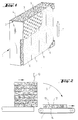
- Figure 1 shows a strictly schematic representation of a panel element of a sound damper panel, panel element 1 being formed by frame 2 provided at least on the two principal surfaces 3 and 4 of the panel (i.e. the front shown in Figure 1 and the back not shown) with an acoustically transparent envelope, formed here by perforated plates. Within frame 2 there is sound-absorbent filling 5 of mineral wool. Such panel elements are disposed one on the other and side by side for the purpose of sound damping, being cramped at the joints. The direction of flow and thus the direction of sound propagation is indicated in Figure 1 by arrow F.
- filling 5 consists of a lamellar plate with altogether four lamellae 6, 7, 8 and 9, the fiber orientation of the lamellar plate perpendicular to principal surfaces 3 and 4 and thus to the perforated plates being indicated by the dotted representation on the front surface of filling 5 apparent from graphically broken perforated plate 3 and by the short lines on the upper face of the panel element.
- This special orientation of the lamellar plate fibers results in very low flow resistance perpendicular to the direction of sound propagation and thus perpendicular to principal surfaces 3 and 4 of panel element 1, but very high flow resistance in the direction of propagation and thus parallel to principal surfaces 3 and 4.
- the thickness of the filling and the bulk density value of the filling are of course dependent on the actual case of application, but it has turned out that lamellar plates or lamellar mats are especially suitable with thicknesses in the range of 10 to 25 cm and bulk densities ⁇ 25 kg/m 3 , in particular ⁇ 60 kg/m 3 . All thickness ranges usual for acoustics can be covered with lamellar plates or mats.
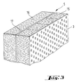
- sound-absorbent filling 5 is formed by mineral wool layer 15 wherein the fibers extend perpendicular to perforated plate 3, as shown schematically in Figure 3.
- mineral wool layer 16 disposed therebehind has a fiber orientation perpendicular thereto so that the fibers of mineral wool layer 16 extend substantially parallel to perforated plate 3.
- a lamellar plate is expediently used for mineral wool layer 15, whereas a usual mineral wool mat or mineral wool plate of usual bulk density can be used for mineral wool layer 16.
- the lamellae are interconnected with a glass mat.
- This glass mat is marked with reference sign 17 strictly schematically in Figure 3.
- the lamellar plate of Figure 1 can also be provided with a glass mat.
Landscapes
- Physics & Mathematics (AREA)
- Engineering & Computer Science (AREA)
- Acoustics & Sound (AREA)
- Multimedia (AREA)
- Soundproofing, Sound Blocking, And Sound Damping (AREA)
- Exhaust Silencers (AREA)
Applications Claiming Priority (2)
| Application Number | Priority Date | Filing Date | Title |
|---|---|---|---|
| DE19600040 | 1996-01-02 | ||
| DE1996100040 DE19600040A1 (de) | 1996-01-02 | 1996-01-02 | Schalldämpferelement, insbesondere für einen Kulissenschalldämfper |
Publications (2)
| Publication Number | Publication Date |
|---|---|
| EP0783164A2 true EP0783164A2 (fr) | 1997-07-09 |
| EP0783164A3 EP0783164A3 (fr) | 1999-04-07 |
Family
ID=7782066
Family Applications (1)
| Application Number | Title | Priority Date | Filing Date |
|---|---|---|---|
| EP96120853A Withdrawn EP0783164A3 (fr) | 1996-01-02 | 1996-12-23 | Elément d'atténuation du son, en particulier pour un écran amortisseur de son |
Country Status (2)
| Country | Link |
|---|---|
| EP (1) | EP0783164A3 (fr) |
| DE (1) | DE19600040A1 (fr) |
Cited By (4)
| Publication number | Priority date | Publication date | Assignee | Title |
|---|---|---|---|---|
| US6196351B1 (en) | 1999-06-04 | 2001-03-06 | Lancaster Glass Fibre Limited | Silencer cartridge |
| EP1428953A1 (fr) * | 2002-12-12 | 2004-06-16 | Rheinhold & Mahla AG | Panneau de délimitation spatiale |
| EP0950160B2 (fr) † | 1997-10-21 | 2011-05-25 | Saint-Gobain Isover | Ensemble facade avec materiau isolant, poreux et translucide |
| CN116078101A (zh) * | 2022-12-14 | 2023-05-09 | 山东丹弗尔医用科技有限公司 | 一种分子筛制氧装置及其使用方法 |
Families Citing this family (2)
| Publication number | Priority date | Publication date | Assignee | Title |
|---|---|---|---|---|
| US5834711A (en) * | 1997-07-09 | 1998-11-10 | Johns Manville International, Inc. | Sound control through resonance damping |
| DE10000418A1 (de) * | 2000-01-07 | 2001-08-09 | Abb Turbo Systems Ag Baden | Verdichter eines Abgasturboladers |
Family Cites Families (8)
| Publication number | Priority date | Publication date | Assignee | Title |
|---|---|---|---|---|
| DE1609728A1 (de) * | 1965-04-23 | 1970-07-30 | Mk Verbundbau Ombh & Co Kg | Schalldaemmende Innenwand |
| US3928097A (en) * | 1974-03-01 | 1975-12-23 | Sauder Industries | Process and machine for manufacturing insulation modules |
| DE8525130U1 (de) * | 1985-09-03 | 1985-10-24 | Gerb Akustik Consult GmbH, 4300 Essen | Schalldämpferkulisse |
| DK156965C (da) * | 1987-03-25 | 1990-03-19 | Rockwool Int | Udvendig, vandafvisende bygningsbeklaedning. |
| GB2231530B (en) * | 1989-05-04 | 1992-10-28 | Hunter Douglas Ind Bv | Sandwich panel core structure |
| GB9004018D0 (en) * | 1990-02-22 | 1990-04-18 | Siderise Ltd | Manufacture of mineral fibre products in layer form |
| DE4127401A1 (de) * | 1991-08-19 | 1993-02-25 | Gruenzweig & Hartmann Montage | Schalldaempferkulisse fuer den einsatz bei hohen temperaturen |
| GB9207865D0 (en) * | 1992-04-09 | 1992-05-27 | Rockwool Ltd | Mineral wool board |
-
1996
- 1996-01-02 DE DE1996100040 patent/DE19600040A1/de not_active Withdrawn
- 1996-12-23 EP EP96120853A patent/EP0783164A3/fr not_active Withdrawn
Non-Patent Citations (1)
| Title |
|---|
| None |
Cited By (4)
| Publication number | Priority date | Publication date | Assignee | Title |
|---|---|---|---|---|
| EP0950160B2 (fr) † | 1997-10-21 | 2011-05-25 | Saint-Gobain Isover | Ensemble facade avec materiau isolant, poreux et translucide |
| US6196351B1 (en) | 1999-06-04 | 2001-03-06 | Lancaster Glass Fibre Limited | Silencer cartridge |
| EP1428953A1 (fr) * | 2002-12-12 | 2004-06-16 | Rheinhold & Mahla AG | Panneau de délimitation spatiale |
| CN116078101A (zh) * | 2022-12-14 | 2023-05-09 | 山东丹弗尔医用科技有限公司 | 一种分子筛制氧装置及其使用方法 |
Also Published As
| Publication number | Publication date |
|---|---|
| DE19600040A1 (de) | 1997-07-03 |
| EP0783164A3 (fr) | 1999-04-07 |
Similar Documents
| Publication | Publication Date | Title |
|---|---|---|
| US5658656A (en) | Use of materials comprising microbubbles as acoustical barriers | |
| KR101960823B1 (ko) | 무향실용 흡음구조체 및 이를 포함하는 무향실 | |
| CN101675226B (zh) | 消音特性可变的消音板 | |
| CA3018165C (fr) | Procede et appareil de regulation acoustique de bruit en metamateriau pour systemes carenes | |
| EP3839940B1 (fr) | Système de silencieux | |
| EP1021686B1 (fr) | Dispositif ameliore pour attenuer le son | |
| US10508828B2 (en) | Splitter and sound attenuator including the same | |
| EP0697051B1 (fr) | Faux plafond | |
| EP0774581B1 (fr) | Compresseur équip avec un pièce de sortrie acoustique | |
| US20090242095A1 (en) | System for reducing acoustic energy | |
| Hansen et al. | Engineering noise control | |
| JPH09510303A (ja) | フォイル吸音体 | |
| EP0783164A2 (fr) | Elément d'atténuation du son, en particulier pour un écran amortisseur de son | |
| WO2003027479A1 (fr) | Tubulure d'admission de moteur fabriquee dans une matiere composite antibruit | |
| RU2439253C1 (ru) | Акустически комфортное помещение с шумозащитным оборудованием | |
| JP2003295867A (ja) | 吸音構造体 | |
| KR101979378B1 (ko) | 스플리터 및 이를 포함하는 소음기 | |
| EP1382031B1 (fr) | Silencieux | |
| EP1319156B1 (fr) | Dispositif insonorisant | |
| CN212047798U (zh) | 一种船舶舱室防火回风消音装置 | |
| RU2299358C1 (ru) | Малошумная вентиляционная установка | |
| JPH074495B2 (ja) | フィルターアタッチメント | |
| JP4303183B2 (ja) | 二重壁構造体 | |
| KR102820030B1 (ko) | 덕트 통과 유체의 소음 감소를 위한 소음저감기 | |
| KR20010025433A (ko) | 덕트용 소음 감쇠장치 |
Legal Events
| Date | Code | Title | Description |
|---|---|---|---|
| PUAI | Public reference made under article 153(3) epc to a published international application that has entered the european phase |
Free format text: ORIGINAL CODE: 0009012 |
|
| AK | Designated contracting states |
Kind code of ref document: A2 Designated state(s): AT BE CH DE DK ES FR LI NL SE |
|
| PUAL | Search report despatched |
Free format text: ORIGINAL CODE: 0009013 |
|
| AK | Designated contracting states |
Kind code of ref document: A3 Designated state(s): AT BE CH DE DK ES FR LI NL SE |
|
| STAA | Information on the status of an ep patent application or granted ep patent |
Free format text: STATUS: THE APPLICATION IS DEEMED TO BE WITHDRAWN |
|
| 18D | Application deemed to be withdrawn |
Effective date: 19990701 |