EP0783172A2 - Transformator, insbesondere für ein Steuergerät eines Heizgerätes - Google Patents
Transformator, insbesondere für ein Steuergerät eines Heizgerätes Download PDFInfo
- Publication number
- EP0783172A2 EP0783172A2 EP96120237A EP96120237A EP0783172A2 EP 0783172 A2 EP0783172 A2 EP 0783172A2 EP 96120237 A EP96120237 A EP 96120237A EP 96120237 A EP96120237 A EP 96120237A EP 0783172 A2 EP0783172 A2 EP 0783172A2
- Authority
- EP
- European Patent Office
- Prior art keywords
- transformer
- housing
- plug contacts
- cover plate
- circuit board
- Prior art date
- Legal status (The legal status is an assumption and is not a legal conclusion. Google has not performed a legal analysis and makes no representation as to the accuracy of the status listed.)
- Granted
Links
Images

Classifications
-
- H—ELECTRICITY
- H01—ELECTRIC ELEMENTS
- H01F—MAGNETS; INDUCTANCES; TRANSFORMERS; SELECTION OF MATERIALS FOR THEIR MAGNETIC PROPERTIES
- H01F27/00—Details of transformers or inductances, in general
- H01F27/28—Coils; Windings; Conductive connections
- H01F27/29—Terminals; Tapping arrangements for signal inductances
-
- H—ELECTRICITY
- H01—ELECTRIC ELEMENTS
- H01F—MAGNETS; INDUCTANCES; TRANSFORMERS; SELECTION OF MATERIALS FOR THEIR MAGNETIC PROPERTIES
- H01F27/00—Details of transformers or inductances, in general
- H01F27/02—Casings
Definitions
- the invention relates to a transformer, in particular for a control unit of a heater, according to the preamble of the main claim and to a control unit equipped with such a transformer.
- transformers the connections of which are in the form of tongues, which, however, because they cannot be inserted directly into the circuit board, must be supplemented with additional cable plug connections for electrical contacting.
- Such transformers are located in particular in the case of heating devices outside the control device or are screwed onto the housing of the control device. We are therefore looking for a transformer that enables inexpensive and space-saving accommodation.
- the transformer with the features of the main claim has the advantage that the connections designed as plug contacts are stabilized by a cover plate and are therefore plugged directly onto the circuit board can. This creates a compact structure that is suitable for confined spaces such as in a control unit of a heater. Furthermore, the cost of individual parts and assembly is reduced by saving on cables and connectors.
- the cover plate has means that fix the plug contacts. These means can preferably be designed as elevations surrounding the plug contacts or as elevations resting on the plug contacts.
- the cover plate has guide pins which are advantageously longer than the plug contacts and engage in corresponding openings in the printed circuit board or in a housing part. This ensures that a precise position and a straight insertion movement is guaranteed when plugging.
- the transformer can very easily be firmly connected to the printed circuit board.
- the cover plate has a sealing lip with which a housing surrounding the control device can be sealed.
- This sealing lip is advantageously designed as a peripheral edge.
- a simple assembly results if the sealing lip points in a direction opposite to the connections.
- the transformer can then be embedded in a wall of the housing comprising the control device, the sealing lip fitting against this housing wall from the inside.
- a transformer according to the invention can advantageously be used for a control unit of a heater.
- the transformer then preferably penetrates one side of a housing comprising the control device and is electrically connected to the printed circuit board. To prevent condensed water from entering the control unit, the penetration area of the housing is sealed with a sealing lip surrounding the transformer.
- Figure 1 shows a transformer according to the invention partially cut from the side along the line I-I in Figure 2
- Figure 2 shows the transformer in an oblique view
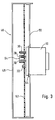
- Figure 3 shows a transformer installed in a housing.
- FIG. 1 shows a transformer 10 with a housing 12 and a coil body 16 surrounded by a sealing compound 14. Connections 18 are connected to the coil body 16 and are passed through the housing 12.
- connections 18 are, as can be seen in particular in FIG. 2, in the form of needle-shaped plug contacts 20 which are received by a cover plate 22 which closes the housing 12 on one side. Within the housing 12, the plug contacts 20 are continued to the coil body 16 and embedded in the potting compound 14.
- the cover plate 22 overlaps the housing 12 at the edges and is firmly connected to it, for example by gluing.
- the cover plate 22 can also be integrally formed on the housing 12 if the entire housing is produced, for example, by an injection molding process.
- FIG. 1 shows an elevation 26, which is in each case one-sided on the plug contacts 20.
- the elevations 24 and 26, respectively, of two adjacent plug contacts 20 are connected to one another via a web 28.
- molded guide pins 30, which are larger in their longitudinal extension than the plug contacts 20 and thus project beyond them.
- mushroom-shaped latching means 32 also extend parallel in the direction of the plug contacts.
- a run-on slope 34 is formed, which merges into a collar 36.
- the latching means 32 is provided with a gap 38 (FIG. 2) which can taper to the bottom. The distance of the collar 36 from the cover plate 22 is 40 greater than the size of the elevations 24 and 26, respectively.
- the cover plate 22 has a peripheral edge 42 which receives a seal 43.
- the seal 43 has the shape of an outwardly extending sealing lip 44, which points in the opposite direction with respect to the plug contacts.
- FIG. 3 shows a control device 46 with a housing 48 which has a rear wall 50 and receives at least one printed circuit board 52.
- a transformer 10 according to the invention extends through the rear wall 50, the plug contacts 20 of which are received by a socket strip 54 arranged on the printed circuit board 52.
- the guide pins 30 and the mushroom-shaped latching means 32 also extend through the printed circuit board 52 (shown rotated by 90 ° in FIG. 3).
- the sealing lip 44 rests on the inside of the rear wall 50.
- the circuit board 52 rests on the elevations 24 and 26, respectively.
- the circuit board 52 is fixed in the housing 48 and then the transformer 10 is plugged onto the circuit board 52.
- the guide pins 30 engage in corresponding openings in the printed circuit board 52 before the plug contacts 20 engage in the receptacles in the socket strip 54.
- the insertion process is finished when the printed circuit board rests on the elevations 24 and 26 and the latching means 32 are engaged.
- the webs 28 and the elevations 24 and 26 serve as spacers between the transformer 10 and the circuit board 52 and the dimension 40 is equal to the thickness of the circuit board 52, so that a secure latching of the latching means 32 is ensured.
- the rear wall 50 which has a cutout corresponding to the contour of the transformer, is pushed on until the rear wall 50 bears against the peripheral edge 42 of the transformer 10. In this position, the rear wall 50 is locked by fastening means, not shown, such as screws, clamps or the like.
- the sealing lip 44 rests on the rear wall 52 and prevents liquids from penetrating.
Landscapes
- Engineering & Computer Science (AREA)
- Power Engineering (AREA)
- Control Of Resistance Heating (AREA)
- Connector Housings Or Holding Contact Members (AREA)
- Central Heating Systems (AREA)
- General Induction Heating (AREA)
- Housings And Mounting Of Transformers (AREA)
Abstract
Description
- Die Erfindung betrifft einen Transformator, insbesondere für ein Steuergerät eines Heizgerätes, nach dem Oberbegriff des Hauptanspruchs sowie ein mit einem solchen Transformator ausgerüstetes Steuergerät.
- Es sind Transformatoren bekannt, deren Anschlüsse die Form von Steckzungen aufweisen, die jedoch, weil sie nicht direkt in die Leiterplatte einsteckbar sind, mit zusätzlichen Kabel-Steckerverbindungen zur elektrischen Kontaktierung ergänzt werden müssen. Derartige Transformatoren sitzen insbesondere bei Heizgeräten außerhalb des Steuergerätes bzw. sind am Gehäuse des Steuergerätes festgeschraubt. Gesucht wird deshalb ein Transformator, der eine kostengünstige und raumsparende Unterbringung ermöglicht.
- Der Transformator mit den Merkmalen des Hauptanspruchs hat den Vorteil, daß die als Steckkontakte ausgebildeten Anschlüsse durch eine Abdeckplatte stabilisiert sind und deshalb direkt auf die Leiterplatte aufgesteckt werden können. Dadurch entsteht ein gedrängter Aufbau der sich für beengte Platzverhältnisse wie in einem Steuergerät eines Heizgerätes eignet. Ferner werden die Einzelteil- und Montagekosten durch die Einsparung der Kabel und Stecker verringert.
- Durch die in den Unteransprüchen aufgeführten Merkmale sind vorteilhafte Weiterbildungen des Transformators nach dem Hauptanspruch möglich.
- Eine mechanische Stabilisierung wird erreicht, wenn die Steckkontakte in den Spulenkörper eingebettet sind. Diese Stabilisierung läßt sich weiter verbessern, wenn die Abdeckplatte die Steckkontakte fixierende Mittel aufweist. Diese Mittel können bevorzugt als die Steckkontakte umgebende Erhebungen oder an den Steckkontakten anliegenden Erhebungen ausgebildet sein. Um beim Einstecken des Transformators in die Leiterplatte ein Verbiegen der Steckkontakte zu vermeiden, weist die Abdeckplatte Führungszapfen auf, die in vorteilhafter Weise länger als die Steckkontakte ausgeführt sind und in korrespondierende Öffnungen in der Leiterplatte oder in einem Gehäuseteil eingreifen. Dadurch ist erreicht, daß beim Aufstecken eine genaue Lageposition und eine geradlinige Einsteckbewegung gewährleistet ist.
- Durch an der Abdeckplatte angeformte Rastmittel kann der Transformator auf sehr einfacheweise fest mit der Leiterplatte verbunden werden.
- Insbesondere wenn am Einsatzort des Transformators bzw. des den Transformator aufnehmenden Steuergeräts eine feuchte Atmosphäre vorherrscht, ist es von Vorteil, wenn die Abdeckplatte eine Dichtlippe aufweist, mit der ein das Steuergerät umgebendes Gehäuse abgedichtet werden kann. In vorteilhafter Weise ist diese Dichtlippe als umlaufender Rand ausgebildet.
- Eine einfache Montage ergibt sich, wenn die Dichtlippe in eine Richtung entgegengesetzt zu den Anschlüssen weist. Der Transformator kann dann in eine Wand des das Steuergerät umfassenden Gehäuses eingelassen sein, wobei sich die Dichtlippe von innen an diese Gehäusewand anlegt.
- Ein erfindungsgemäßer Transformator kann in vorteilhafter Weise für ein Steuergerät eines Heizgerätes verwendet werden. Der Transformator durchdringt dann vorzugsweise eine Seite eines das Steuergerät umfassenden Gehäuses und ist elektrisch mit der Leiterplatte verbunden. Um zu vermeiden, daß Kondenswasser in das Steuergerät eindringt, wird mit einer den Transformator umgebenden Dichtlippe der Durchdringungsbereich des Gehäuses abgedichtet.
- In der Zeichnung ist ein Ausführungsbeispiel dargestellt und in der nachfolgenden Beschreibung näher erläutert. Figur 1 zeigt einen erfindungsgemäßen Transformator von der Seite teilweise geschnitten nach der Linie I-I in Figur 2, Figur 2 den Transformator in einer Schrägansicht und Figur 3 einen in ein Gehäuse eingebauten Transformator.
- In Figur 1 ist ein Transformator 10 dargestellt mit einem Gehäuse 12 und einem von einer Vergußmasse 14 umgebenden Spulenkörper 16. Mit dem Spulenkörper 16 sind Anschlüsse 18 verbunden, die durch das Gehäuse 12 hindurchgeführt sind.
- Die Anschlüsse 18 sind, wie insbesondere in Figur 2 zu sehen ist, als nadelförmige Steckkontakte 20 ausgebildet, die von einer das Gehäuse 12 einseitig abschließenden Abdeckplatte 22 aufgenommen sind. Innerhalb des Gehäuses 12 sind die Steckkontakte 20 bis zum Spulenkörper 16 weitergeführt und in die Vergußmasse 14 eingebettet.
- Die Abdeckplatte 22 übergreift das Gehäuse 12 an den Rändern und ist mit diesem beispielsweise durch Verkleben fest verbunden. Die Abdeckplatte 22 kann aber auch einstückig an das Gehäuse 12 angeformt sein, wenn das gesamte Gehäuse beispielsweise in einem Spritzgußverfahren hergestellt wird.
- An der Austrittsstelle der Steckkontakte 20 aus der Abdeckplatte 22 weist die Abdeckplatte 22 die Steckkontakte 20 umgebende Erhebungen 24 (Figur 2) auf. In Figur 1 ist als Alternative zu den umgreifenden Erhebungen 24 eine jeweils einseitig an den Steckkontakten 20 anliegende Erhebung 26 gezeigt. Die Erhebungen 24 bzw. 26 jeweils zweier benachbarter Steckkontakte 20 sind über einen Steg 28 miteinander verbunden.
- Neben den Steckkontakten 20 erstrecken sich parallel zu den Steckkontakten 20 an die Abdeckplatte 22 angeformte Führungszapfen 30, die in Ihrer Längserstreckung größer sind als die Steckkontakte 20 und diese damit überragen. Ebenfalls neben den Steckkontakten 20 angeordnet erstrecken sich ebenfalls parallel in Richtung der Steckkontakte pilzförmige Rastmittel 32. Am oberen Ende der Rastmittel 32 ist eine Anlaufschräge 34 angeformt, die in einen Kragen 36 übergeht. Vom oberen Ende ausgehend ist das Rastmittel 32 mit einem Spalt 38 versehen (Figur 2), der nach unten spitz zulaufen kann. Der Abstand des Kragens 36 von der Abdeckplatte 22 ist um das Maß 40 größer als die Größe der Erhebungen 24 bzw. 26.
- Die Abdeckplatte 22 weist einen umlaufenden Rand 42 auf, der eine Dichtung 43 aufnimmt. Die Dichtung 43 weist die Form einer sich nach außen erstreckenden, bezogen auf die Steckkontakte in entgegengesetzter Richtung weisenden Dichtlippe 44 auf.
- In Figur 3 ist ein Steuergerät 46 dargestellt, mit einem Gehäuse 48, das eine Rückwand 50 aufweist und mindestens eine Leiterplatte 52 aufnimmt. Durch die Rückwand 50 erstreckt sich ein erfindungsgemäßer Transformator 10, dessen Steckkontakte 20 von einer auf der Leiterplatte 52 angeordneten Buchsenleiste 54 aufgenommen sind. Ebenfalls durch die Leiterplatte 52 hindurch erstrecken sich die Führungszapfen 30 und die pilzförmigen Rastmittel 32 (in Figur 3 um 90° gedreht gezeichnet). Die Dichtlippe 44 liegt an der Innenseite der Rückwand 50 an. Ferner liegt die Leiterplatte 52 auf den Erhebungen 24 bzw. 26 auf.
- Bei der Montage wird die Leiterplatte 52 im Gehäuse 48 fixiert und dann der Transformator 10 auf die Leiterplatte 52 aufgesteckt. Dabei greifen zuerst die Führungszapfen 30 in korrespondierende Öffnungen der Leiterplatte 52 bevor die Steckkontakte 20 in die Aufnahmen der Buchsenleiste 54 greifen. Der Einsteckvorgang ist beendet, wenn die Leiterplatte auf den Erhebungen 24 bzw. 26 aufliegt und die Rastmittel 32 eingerastet sind. Die Stege 28 und die Erhebungen 24 bzw. 26 dienen als Abstandshalter zwischen dem Transformator 10 und der Leiterplatte 52 und das Maß 40 ist gleich der Dicke der Leiterplatte 52, sodaß ein sicheres Einrasten der Rastmittel 32 gewährleistet ist. Zum Verschließen des Gehäuses 48 des Steuergeräts 46 wird die Rückwand 50, die eine Aussparung entsprechend der Kontur des Transformators aufweist, aufgeschoben, bis die Rückwand 50 am umlaufenden Rand 42 des Transformators 10 anliegt. In dieser Position wird die Rückwand 50 durch nicht dargestellte Befestigungsmittel wie Schrauben, Klemmen oder dergleichen arretiert. Die Dichtlippe 44 legt sich an die Rückwand 52 an und verhindert ein Eindringen von Flüssigkeiten. Durch die Arretierung der Rückwand 50 und die Befestigung der Leiterplatte 52 innerhalb des Gehäuses 48 ist auch der Transformator in seiner Lage fixiert, da er einerseits mit den Stegen 28 und Erhebungen 24 bzw. 26 an der Leiterplatte 52 und andererseits mit dem umlaufenden Rand 42 an der Rückwand 52 fest anliegt.
Claims (10)
- Transformator, insbesondere für ein Steuergerät eines Heizgerätes, mit einem von einem Gehäuse umfaßten Spulenkörper, der mit durch das Gehäuse hindurchgeführten Anschlüssen für eine elektrische Kontaktierung verbunden ist, dadurch gekennzeichnet, daß das Gehäuse (12) eine die als Steckkontakte (20) ausgebildeten Anschlüsse (18) aufnehmende Abdeckplatte (22) aufweist.
- Transformator nach Anspruch 1, dadurch gekennzeichnet, daß die Steckkontakte (20) in die den Spulenkörper (16) umgebende Vergußmasse (14) eingebettet sind.
- Transformator nach Anspruch 1 oder 2, dadurch gekennzeichnet, daß die Abdeckplatte (22) die Steckkontakte (20) fixierende Mittel (24, 26) aufweist.
- Transformator nach Anspruch 3, dadurch gekennzeichnet, daß die Mittel als die Steckkontakte (20) umgebenden Erhebungen (24) oder an den Steckkontakten anliegenden Erhebungen (26) ausgestaltet sind.
- Transformator nach einem der Ansprüche 1 bis 4, dadurch gekennzeichnet, daß die Abdeckplatte (22) Führungszapfen (30) aufweist.
- Transformator nach einem der Ansprüche 1 bis 5, dadurch gekennzeichnet, daß die Abdeckplatte (22) eine als Dichtlippe (44) ausgebildete Dichtung (43) aufweist.
- Transformator nach Anspruch 6, dadurch gekennzeichnet, daß die Dichtlippe (44) die äußere Kontur des Transformators (10) umgibt und an einen umlaufenden Rand (42) angeformt ist.
- Transformator nach Anspruch 6 oder 7, dadurch gekennzeichnet, daß die Dichtlippe (44) in eine Richtung entgegengesetzt zu den Anschlüssen (18) weist.
- Steuergerät für ein Heizgerät, mit einem Gehäuse und mit mindestens einer Leiterplatte , dadurch gekennzeichnet, daß eine Seite (50) des Gehäuses (48) von einem Transformator (10) nach einem der vorhergehenden Ansprüche durchdrungen ist, der mit der Leiterplatte (52) elektrisch verbunden ist.
- Steuergerät nach Anspruch 9, dadurch gekennzeichnet, daß der Transformator (10) mit einer angeformten Dichtlippe (44) den Durchdringungsbereich abdichtet.
Applications Claiming Priority (2)
| Application Number | Priority Date | Filing Date | Title |
|---|---|---|---|
| DE19600083A DE19600083A1 (de) | 1996-01-03 | 1996-01-03 | Transformator, insbesondere für ein Steuergerät eines Heizgerätes |
| DE19600083 | 1996-01-03 |
Publications (3)
| Publication Number | Publication Date |
|---|---|
| EP0783172A2 true EP0783172A2 (de) | 1997-07-09 |
| EP0783172A3 EP0783172A3 (de) | 1997-10-22 |
| EP0783172B1 EP0783172B1 (de) | 2002-04-10 |
Family
ID=7782101
Family Applications (1)
| Application Number | Title | Priority Date | Filing Date |
|---|---|---|---|
| EP96120237A Expired - Lifetime EP0783172B1 (de) | 1996-01-03 | 1996-12-17 | Transformator, insbesondere für ein Steuergerät eines Heizgerätes |
Country Status (4)
| Country | Link |
|---|---|
| EP (1) | EP0783172B1 (de) |
| AT (1) | ATE216123T1 (de) |
| DE (2) | DE19600083A1 (de) |
| TR (1) | TR199601071A2 (de) |
Cited By (2)
| Publication number | Priority date | Publication date | Assignee | Title |
|---|---|---|---|---|
| EP1515596A3 (de) * | 2003-09-15 | 2005-04-13 | Robert Bosch Gmbh | Bauelemente-Halter |
| WO2014200459A1 (en) | 2013-06-10 | 2014-12-18 | Schneider Electric Solar Inverters Usa, Inc. | An electronics system and method of forming same |
Family Cites Families (5)
| Publication number | Priority date | Publication date | Assignee | Title |
|---|---|---|---|---|
| US4112481A (en) * | 1977-05-05 | 1978-09-05 | Wescom, Inc. | Miniature multi-impedance transformer module |
| DE3236575A1 (de) * | 1982-10-02 | 1984-04-05 | Viessmann Werke Kg, 3559 Allendorf | Steuer- und regelungsgeraet fuer heizungsanlagen |
| DE3321721A1 (de) * | 1983-06-16 | 1984-12-20 | Vogt Gmbh & Co Kg, 8391 Erlau | Universal-vergussgehaeuse fuer ringkerndrosseln bzw. ringkerntransformatoren |
| DE8628266U1 (de) * | 1986-10-23 | 1987-03-12 | Lorenzen, Klaus, 74405 Gaildorf | Vorrichtung zur Lagerung von elektrischen Bauelementen auf einer Leiterplatte |
| US5281154A (en) * | 1992-11-24 | 1994-01-25 | Molex Incorporated | Electrical connector assembly with printed circuit board layout |
-
1996
- 1996-01-03 DE DE19600083A patent/DE19600083A1/de not_active Withdrawn
- 1996-12-17 AT AT96120237T patent/ATE216123T1/de not_active IP Right Cessation
- 1996-12-17 EP EP96120237A patent/EP0783172B1/de not_active Expired - Lifetime
- 1996-12-17 DE DE59609056T patent/DE59609056D1/de not_active Expired - Lifetime
- 1996-12-27 TR TR96/01071A patent/TR199601071A2/xx unknown
Non-Patent Citations (1)
| Title |
|---|
| None |
Cited By (6)
| Publication number | Priority date | Publication date | Assignee | Title |
|---|---|---|---|---|
| EP1515596A3 (de) * | 2003-09-15 | 2005-04-13 | Robert Bosch Gmbh | Bauelemente-Halter |
| WO2014200459A1 (en) | 2013-06-10 | 2014-12-18 | Schneider Electric Solar Inverters Usa, Inc. | An electronics system and method of forming same |
| EP3008980A4 (de) * | 2013-06-10 | 2017-01-25 | Schneider Electric Solar Inverters USA, Inc. | Elektronisches system und verfahren zur herstellung davon |
| US9934899B2 (en) | 2013-06-10 | 2018-04-03 | Schneider Electric Solar Inverters Usa, Inc. | Electronics system and method of forming same |
| EP3500074A1 (de) * | 2013-06-10 | 2019-06-19 | Schneider Electric Solar Inverters USA, Inc. | Elektroniksystem und verfahren zur herstellung davon |
| US10431370B2 (en) | 2013-06-10 | 2019-10-01 | Schneider Electric Solar Inverters Usa, Inc. | Electronics system and method of forming same |
Also Published As
| Publication number | Publication date |
|---|---|
| ATE216123T1 (de) | 2002-04-15 |
| EP0783172A3 (de) | 1997-10-22 |
| EP0783172B1 (de) | 2002-04-10 |
| DE19600083A1 (de) | 1997-07-10 |
| DE59609056D1 (de) | 2002-05-16 |
| TR199601071A2 (tr) | 1997-07-21 |
Similar Documents
| Publication | Publication Date | Title |
|---|---|---|
| DE3437988A1 (de) | Elektrisches schaltgeraet | |
| EP0338394A1 (de) | Elektromotor, insbesondere Wischermotor zum Antrieb einer Scheibenwischeranlage in einem Kraftfahrzeug | |
| EP0368115A2 (de) | Zentrale Stromverteilungsanordnung, insbesondere für Kraftfahrzeuge | |
| DE102014205744B4 (de) | Steuergerät für ein Fahrzeugheizgerät | |
| DE102005029686A1 (de) | Antenne und Mittel zum Befestigen der Antenne auf einem Fahrzeug sowie zum Anschließen der Antenne an ein oder mehrere Kabel eines im Fahrzeug verlegten Kabelbaumes | |
| EP2551978B1 (de) | Vorrichtung zur Durchführung einer elektrischen Leitung durch ein Gehäuse | |
| DE3201142A1 (de) | Steckverbinder | |
| EP0818133A1 (de) | Steuergerät für ein kraftfahrzeug | |
| DE4400476C2 (de) | Einrichtung für einen Aktor | |
| DE19816216C2 (de) | Elektrischer Stecker und Steckverbindung | |
| EP1139493B1 (de) | Elektrischer Verbinder zum Anschluss von elektrischen Leitern an ein elektrisches Gerät | |
| DE3432856C2 (de) | ||
| EP3309904B1 (de) | Gehäuse zum anschliessen wenigstens einer kabellitze eines kabels | |
| EP0783172A2 (de) | Transformator, insbesondere für ein Steuergerät eines Heizgerätes | |
| EP2208646A1 (de) | Anschlussgehäuse zum Einbau in eine Fahrzeugkarosserie | |
| DE102012102849A1 (de) | Befestigung und Abdichtung eines Steckanschlussmoduls in einer Gehäusewandung | |
| DE2448111A1 (de) | Anordnung zum anschluss elektrischer leitungen an ein elektrisches geraet | |
| DE29603678U1 (de) | Elektrische Steckverbindung für Folienleiter | |
| EP0575571B1 (de) | Gehäuse für ein elektronisches steuergerät | |
| DE69105325T2 (de) | Zündanlage für innere Brennkraftmaschine. | |
| DE10004220A1 (de) | Vorrichtung zur Klemmbefestigung einer Flachbatterie | |
| DE19603868C1 (de) | Klemmenplatte für einen Elektromotor | |
| WO2001069629A1 (de) | Vorrichtung zur lagerichtigen befestigung einer leiterplatte | |
| EP1220368A2 (de) | Steckverbinder für flexible Flachbandleiter | |
| DE9400326U1 (de) | Einrichtung für einen Aktor |
Legal Events
| Date | Code | Title | Description |
|---|---|---|---|
| PUAI | Public reference made under article 153(3) epc to a published international application that has entered the european phase |
Free format text: ORIGINAL CODE: 0009012 |
|
| AK | Designated contracting states |
Kind code of ref document: A2 Designated state(s): AT DE ES FR GB IT NL PT |
|
| PUAL | Search report despatched |
Free format text: ORIGINAL CODE: 0009013 |
|
| AK | Designated contracting states |
Kind code of ref document: A3 Designated state(s): AT DE ES FR GB IT NL PT |
|
| 17P | Request for examination filed |
Effective date: 19980422 |
|
| 17Q | First examination report despatched |
Effective date: 19990504 |
|
| GRAG | Despatch of communication of intention to grant |
Free format text: ORIGINAL CODE: EPIDOS AGRA |
|
| GRAG | Despatch of communication of intention to grant |
Free format text: ORIGINAL CODE: EPIDOS AGRA |
|
| GRAH | Despatch of communication of intention to grant a patent |
Free format text: ORIGINAL CODE: EPIDOS IGRA |
|
| REG | Reference to a national code |
Ref country code: GB Ref legal event code: IF02 |
|
| GRAH | Despatch of communication of intention to grant a patent |
Free format text: ORIGINAL CODE: EPIDOS IGRA |
|
| GRAA | (expected) grant |
Free format text: ORIGINAL CODE: 0009210 |
|
| AK | Designated contracting states |
Kind code of ref document: B1 Designated state(s): AT DE ES FR GB IT NL PT |
|
| PG25 | Lapsed in a contracting state [announced via postgrant information from national office to epo] |
Ref country code: NL Free format text: LAPSE BECAUSE OF FAILURE TO SUBMIT A TRANSLATION OF THE DESCRIPTION OR TO PAY THE FEE WITHIN THE PRESCRIBED TIME-LIMIT Effective date: 20020410 Ref country code: IT Free format text: LAPSE BECAUSE OF FAILURE TO SUBMIT A TRANSLATION OF THE DESCRIPTION OR TO PAY THE FEE WITHIN THE PRESCRIBED TIME-LIMIT;WARNING: LAPSES OF ITALIAN PATENTS WITH EFFECTIVE DATE BEFORE 2007 MAY HAVE OCCURRED AT ANY TIME BEFORE 2007. THE CORRECT EFFECTIVE DATE MAY BE DIFFERENT FROM THE ONE RECORDED. Effective date: 20020410 Ref country code: GB Free format text: LAPSE BECAUSE OF FAILURE TO SUBMIT A TRANSLATION OF THE DESCRIPTION OR TO PAY THE FEE WITHIN THE PRESCRIBED TIME-LIMIT Effective date: 20020410 Ref country code: FR Free format text: LAPSE BECAUSE OF FAILURE TO SUBMIT A TRANSLATION OF THE DESCRIPTION OR TO PAY THE FEE WITHIN THE PRESCRIBED TIME-LIMIT Effective date: 20020410 |
|
| REF | Corresponds to: |
Ref document number: 216123 Country of ref document: AT Date of ref document: 20020415 Kind code of ref document: T |
|
| REF | Corresponds to: |
Ref document number: 59609056 Country of ref document: DE Date of ref document: 20020516 |
|
| PG25 | Lapsed in a contracting state [announced via postgrant information from national office to epo] |
Ref country code: PT Free format text: LAPSE BECAUSE OF FAILURE TO SUBMIT A TRANSLATION OF THE DESCRIPTION OR TO PAY THE FEE WITHIN THE PRESCRIBED TIME-LIMIT Effective date: 20020710 |
|
| NLV1 | Nl: lapsed or annulled due to failure to fulfill the requirements of art. 29p and 29m of the patents act | ||
| GBV | Gb: ep patent (uk) treated as always having been void in accordance with gb section 77(7)/1977 [no translation filed] |
Effective date: 20020410 |
|
| PG25 | Lapsed in a contracting state [announced via postgrant information from national office to epo] |
Ref country code: ES Free format text: LAPSE BECAUSE OF FAILURE TO SUBMIT A TRANSLATION OF THE DESCRIPTION OR TO PAY THE FEE WITHIN THE PRESCRIBED TIME-LIMIT Effective date: 20021030 |
|
| PG25 | Lapsed in a contracting state [announced via postgrant information from national office to epo] |
Ref country code: AT Free format text: LAPSE BECAUSE OF NON-PAYMENT OF DUE FEES Effective date: 20021217 |
|
| EN | Fr: translation not filed | ||
| PLBE | No opposition filed within time limit |
Free format text: ORIGINAL CODE: 0009261 |
|
| STAA | Information on the status of an ep patent application or granted ep patent |
Free format text: STATUS: NO OPPOSITION FILED WITHIN TIME LIMIT |
|
| 26N | No opposition filed |
Effective date: 20030113 |
|
| REG | Reference to a national code |
Ref country code: DE Ref legal event code: R084 Ref document number: 59609056 Country of ref document: DE Effective date: 20120919 |
|
| PGFP | Annual fee paid to national office [announced via postgrant information from national office to epo] |
Ref country code: DE Payment date: 20130225 Year of fee payment: 17 |
|
| REG | Reference to a national code |
Ref country code: DE Ref legal event code: R119 Ref document number: 59609056 Country of ref document: DE |
|
| REG | Reference to a national code |
Ref country code: DE Ref legal event code: R119 Ref document number: 59609056 Country of ref document: DE Effective date: 20140701 |
|
| PG25 | Lapsed in a contracting state [announced via postgrant information from national office to epo] |
Ref country code: DE Free format text: LAPSE BECAUSE OF NON-PAYMENT OF DUE FEES Effective date: 20140701 |