EP0783190A1 - Antenne passive x-y-z pour transpondeur - Google Patents
Antenne passive x-y-z pour transpondeur Download PDFInfo
- Publication number
- EP0783190A1 EP0783190A1 EP97100021A EP97100021A EP0783190A1 EP 0783190 A1 EP0783190 A1 EP 0783190A1 EP 97100021 A EP97100021 A EP 97100021A EP 97100021 A EP97100021 A EP 97100021A EP 0783190 A1 EP0783190 A1 EP 0783190A1
- Authority
- EP
- European Patent Office
- Prior art keywords
- antenna
- coil
- transponder
- oriented
- signals
- Prior art date
- Legal status (The legal status is an assumption and is not a legal conclusion. Google has not performed a legal analysis and makes no representation as to the accuracy of the status listed.)
- Granted
Links
- 229910000859 α-Fe Inorganic materials 0.000 claims abstract description 29
- 238000010586 diagram Methods 0.000 description 8
- 239000003990 capacitor Substances 0.000 description 3
- 230000005540 biological transmission Effects 0.000 description 2
- 230000004907 flux Effects 0.000 description 2
- 241001640034 Heteropterys Species 0.000 description 1
- 241000282414 Homo sapiens Species 0.000 description 1
- 241001465754 Metazoa Species 0.000 description 1
- 230000015556 catabolic process Effects 0.000 description 1
- 238000010276 construction Methods 0.000 description 1
- 230000008878 coupling Effects 0.000 description 1
- 238000010168 coupling process Methods 0.000 description 1
- 238000005859 coupling reaction Methods 0.000 description 1
- 238000006731 degradation reaction Methods 0.000 description 1
- 230000004048 modification Effects 0.000 description 1
- 238000012986 modification Methods 0.000 description 1
- 230000010363 phase shift Effects 0.000 description 1
- 238000006467 substitution reaction Methods 0.000 description 1
Images


Classifications
-
- H—ELECTRICITY
- H01—ELECTRIC ELEMENTS
- H01Q—ANTENNAS, i.e. RADIO AERIALS
- H01Q7/00—Loop antennas with a substantially uniform current distribution around the loop and having a directional radiation pattern in a plane perpendicular to the plane of the loop
- H01Q7/06—Loop antennas with a substantially uniform current distribution around the loop and having a directional radiation pattern in a plane perpendicular to the plane of the loop with core of ferromagnetic material
- H01Q7/08—Ferrite rod or like elongated core
-
- H—ELECTRICITY
- H01—ELECTRIC ELEMENTS
- H01Q—ANTENNAS, i.e. RADIO AERIALS
- H01Q21/00—Antenna arrays or systems
- H01Q21/28—Combinations of substantially independent non-interacting antenna units or systems
-
- H—ELECTRICITY
- H01—ELECTRIC ELEMENTS
- H01Q—ANTENNAS, i.e. RADIO AERIALS
- H01Q7/00—Loop antennas with a substantially uniform current distribution around the loop and having a directional radiation pattern in a plane perpendicular to the plane of the loop
-
- G—PHYSICS
- G07—CHECKING-DEVICES
- G07C—TIME OR ATTENDANCE REGISTERS; REGISTERING OR INDICATING THE WORKING OF MACHINES; GENERATING RANDOM NUMBERS; VOTING OR LOTTERY APPARATUS; ARRANGEMENTS, SYSTEMS OR APPARATUS FOR CHECKING NOT PROVIDED FOR ELSEWHERE
- G07C9/00—Individual registration on entry or exit
- G07C9/00174—Electronically operated locks; Circuits therefor; Nonmechanical keys therefor, e.g. passive or active electrical keys or other data carriers without mechanical keys
- G07C9/00309—Electronically operated locks; Circuits therefor; Nonmechanical keys therefor, e.g. passive or active electrical keys or other data carriers without mechanical keys operated with bidirectional data transmission between data carrier and locks
Definitions
- This invention relates generally to electronic circuits, and more particularly to a passive entry X-Y-Z transponder or reader antenna.
- the effectiveness of conventional antennas for transmission and reception may vary according to a number of factors relating to the antenna environment, including the orientation of the antenna relative to the reader and the modulated RF carrier signal. If a conventional transponder antenna is improperly aligned relative to the reader, the incoming or outgoing RF carrier signal may be degraded and the data represented by the signal misinterpreted.
- an omnidirectional transponder antenna which substantially eliminates or reduces disadvantages or problems associated with prior art transponders and antennas.
- the three antenna coils comprise one preferably flat air coil and two ferrite antenna coils, with the ferrite coils oriented at different angles relative to each other.
- Each antenna is coupled to a resonant tuning circuit having LC's, and, when the antenna is receiving RF signals, the DC voltages from the tuning circuits are superimposed and added in order to construct a single supply voltage.
- one air coil may be used with one ferrite antenna coil.
- FIG. 1 is a graphical representation of one arrangement of antennas according to the present invention.
- one embodiment of the invention comprises an air coil 10, shown here oriented in the Y direction, and one or more ferrite coil antennas.
- FIG. 1 shows two such ferrite coil antennas 12 and 14, oriented in the X and Z directions, respectively.
- the ferrite antennas are therefore oriented approximately 90 degrees relative to each other, and from the air coil 10.
- the ferrite antennas 12 and 14 may be of any conventional construction, such as antennas used in conventional automobile-type transponders.
- the individual air coil 10 and the ferrite antenna coils 12 and 14 have a dipole-type pattern with maxima and minima.
- a transponder unit is able to effectively receive and reconstruct RF carrier signals which are oriented in any direction relative to the transponder with minimal degradation.
- the strength of a received RF signal would vary according to whether the antenna was properly aligned in the plane of the signal. Even if the antenna were located adjacent a maxima of the carrier signal, the antenna's ability to receive the signal accurately could be reduced significantly if the antenna were improperly oriented relative to the plane of the signal.
- a transponder antenna constructed according to the present invention is suitable for a wide range of applications for which conventional antenna arrangements are inadequate, such as applications in which either the transponder or reader unit, or both, are moveable relative to each other, including, for example, when the transponder or reader units are mounted on vehicles or carried by human beings.
- FIG. 2 illustrates an example of three antennas 10, 12 and 14 mounted within a transponder unit in order to achieve the arrangement depicted in the graphical representation of FIG. 1.
- ferrite coil antennas 12 and 14 are oriented with the longitudinal axis of the coils oriented in the X and Z directions, respectively.
- the direction of flux or transmission for ferrite coil antennas lies along this longitudinal axis (in a direction relative to the coil indicated by the "right-hand rule", or parallel to the "barrel" of the generally tubular coil), so that orienting the coils 12 and 14 along these axes will cause the coils 12 and 14 to transmit and receive RF carrier signals along the X and Z axes, respectively.
- Air coil 10 is positioned within the transponder unit as shown in FIG. 2.
- Air coil 10 is a generally flat planar coil which operates such that the direction of flux (the direction in which signals are transmitted from and received by the coil) is perpendicular to the plane of the coil.
- the generally flat planar shape of air coil 10 permits antennas 10, 12 and 14 to be arranged so that the ferrite coils 12 and 14 lie in generally the same plane as air coil 10, so that the antenna arrangement occupies very little space. Since the arrangement depicted in FIG. 2 does not occupy a significant amount of space in the Y-direction, the coil arrangement of the present invention therefore may be used in smaller and thinner (for example, hand-held) transponders than can conventional antenna arrangements, while still enabling the transponder to effectively transmit and receive omnidirectionally.
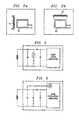
- FIGs. 2A and 2B illustrate alternative embodiments of the present invention in which only one ferrite coil antenna is provided in combination with the air coil 10.
- FIG. 2A shows the air coil 10 aligned in the Z-direction, in combination with one ferrite coil antenna aligned in the Y-direction.
- FIG. 2B shows an air coil 10 aligned in the Z-direction in combination with a ferrite air coil aligned in the X-direction.
- the alignment of the antennas shown in FIGs. 2, 2A and 2B could be altered without departing from the scope of the present invention.
- FIGS. 3 and 4 illustrate arrangements of resonant tuning circuits that may be used with the antennas depicted in FIG. 2.
- each resonant tuning circuit comprises an inductor, a capacitor, and a diode.
- Each of the antennas 10, 12 and 14, are coupled independently to a separate resonant tuning circuit, and the three resonant tuning circuits are coupled together either in series, as shown in FIG. 3, or in parallel, as shown in FIG. 4.
- FIG. 3 shows three resonant tuning circuits coupled in series.
- Each resonant tuning circuit comprises an inductor and a capacitor, and the three resonant tuning circuits are coupled together with diodes.
- Points 20, 22 and 24 indicate where an oscillator and/or modulator circuit (described below) may be coupled when the transponder antenna is adapted to transmit signals.
- FIG. 3A is a block diagram depicting the antenna arrangement when the circuits are coupled in series.
- FIG. 3B is a block diagram depicting the antenna arrangement when two circuits are coupled in series.
- FIG. 4 shows three resonant tuning circuits coupled in parallel.
- each resonant tuning circuit comprises an inductor and a capacitor, and the three resonant tuning circuits are coupled together with diodes.
- Points 20, 22 and 24 indicate where an oscillator and/or modulator circuit (described below) may be coupled when the transponder antenna is adapted to transmit signals.
- FIG. 4A is a block diagram of an antenna arrangement when the circuits are coupled in parallel.
- FIG. 4B is a block diagram depicting the antenna arrangement when two circuits are coupled in parallel.
- a similar antenna arrangement may also be provided in a reader unit, in order ro provide omnidirectionality at a remote location.
- the three antennas 10, 12 and 14 operate to independently receive components of the carrier signal oriented in the Y, X and Z directions, respectively.
- the received signals are passed to the resonant tuning circuit connected to each antenna.
- the series arrangement of the resonant tuning circuits shown in FIG. 3 act to superimpose and add the DC voltage components of the received carrier signal, to reconstruct the signal components into a single DC voltage signal representative of the signal which was transmitted from the remote location.
- the parallel arrangement of the resonant tuning circuits shown in FIG. 4 operates such that the highest induced voltage either supplies all RF circuits, or supplies only the RF circuit having the highest individual voltage.
- each of the antennas 10, 12 and 14 may be independently coupled either to a modulated oscillator, or to a passive reactance modulator.
- FIG. 5 shows a reactance modulator circuit configured in a full-duplex, back scatter mode, that may be coupled to each of the antennas 10, 12 or 14, and
- FIG. 6 shows a circuit for a modulated active oscillator which may also be used.
- the reader unit may be provided with two or three air coil antennas oriented in different directions, instead of a single air coil in combination with one or two ferrite coil antennas.
Landscapes
- Near-Field Transmission Systems (AREA)
- Radar Systems Or Details Thereof (AREA)
- Variable-Direction Aerials And Aerial Arrays (AREA)
Applications Claiming Priority (2)
| Application Number | Priority Date | Filing Date | Title |
|---|---|---|---|
| US947896P | 1996-01-02 | 1996-01-02 | |
| US9478 | 1996-01-02 |
Publications (2)
| Publication Number | Publication Date |
|---|---|
| EP0783190A1 true EP0783190A1 (fr) | 1997-07-09 |
| EP0783190B1 EP0783190B1 (fr) | 2001-10-04 |
Family
ID=21737899
Family Applications (1)
| Application Number | Title | Priority Date | Filing Date |
|---|---|---|---|
| EP19970100021 Expired - Lifetime EP0783190B1 (fr) | 1996-01-02 | 1997-01-02 | Antenne passive x-y-z pour transpondeur |
Country Status (2)
| Country | Link |
|---|---|
| EP (1) | EP0783190B1 (fr) |
| DE (1) | DE69707024T2 (fr) |
Cited By (26)
| Publication number | Priority date | Publication date | Assignee | Title |
|---|---|---|---|---|
| DE19718423A1 (de) * | 1997-04-30 | 1998-11-05 | Siemens Ag | Tragbarer Signalempfänger |
| EP0903456A1 (fr) * | 1997-09-11 | 1999-03-24 | Delco Electronics Corporation | Récepteur destiné à un système télécommandé d'entrée sans clef pour véhicules automobiles |
| EP0898255A3 (fr) * | 1997-08-22 | 1999-12-22 | Uni Electronics Industry Co., Ltd. | Etiquette pour la prévention du vol |
| FR2812427A1 (fr) * | 2000-07-28 | 2002-02-01 | Inside Technologies | Etiquette electronique sans contact pour objet tridimensionnel |
| EP1178170A1 (fr) * | 2000-08-04 | 2002-02-06 | Delphi Technologies, Inc. | Système de commande à distance pour véhicule automobile avec une antenne de réception améliorée |
| FR2813256A1 (fr) * | 2000-08-25 | 2002-03-01 | Siemens Ag | Systeme antivol pour vehicule automobile et procede de mise en oeuvre d'un tel systeme antivol |
| EP1189306A1 (fr) * | 2000-09-19 | 2002-03-20 | Land Rover | Système de sécurité |
| EP1313169A3 (fr) * | 2001-11-15 | 2003-09-03 | Alps Electric Co., Ltd. | Antenne récéptrice et méthode d'agencement pour cet antenne d' un dispositif de communication |
| EP1313168A3 (fr) * | 2001-11-15 | 2003-09-03 | Alps Electric Co., Ltd. | Méthode d 'agencement d'une antenne réceptrice d'un dispositif de communication |
| WO2003034349A3 (fr) * | 2001-10-18 | 2003-11-06 | Microchip Tech Inc | Reduction de la directivite de l'orientation et amelioration de la distance de fonctionnement des bobines de detecteurs magnetiques dans un champ magnetique |
| ES2200652A1 (es) * | 2001-11-07 | 2004-03-01 | Predan S A | Antena monolitica con sensibilidad en los tres ejes para aplicaciones en transpondedores para automocion. |
| EP1083280A3 (fr) * | 1999-09-10 | 2004-03-10 | Kiekert Aktiengesellschaft | Dispositif d'actionnement et/ou de fermeture sans clé, notamment pour véhicule automobile |
| US6721611B2 (en) | 1997-09-17 | 2004-04-13 | Logitech Europe S.A. | Antenna system and apparatus for radio-frequency wireless keyboard |
| DE10192529B4 (de) * | 2000-07-19 | 2004-05-13 | Logitech Europe S.A. | Antennensystem |
| US6799722B2 (en) | 2001-12-04 | 2004-10-05 | Balluff Gmbh | Code carrier device |
| WO2004107276A1 (fr) * | 2003-06-03 | 2004-12-09 | Huf Hülsbeck & Fürst Gmbh & Co. Kg | Dispositif de controle d'acces electronique |
| EP1136955A3 (fr) * | 2000-03-20 | 2006-04-05 | Philips Intellectual Property & Standards GmbH | Dispositif pour un système d'accès sécurisé |
| DE102011050129A1 (de) | 2011-05-05 | 2012-11-08 | Maxim Integrated Gmbh | Transponder |
| DE102011051456A1 (de) | 2011-06-30 | 2013-01-03 | Maxim Integrated Gmbh | Transponder |
| DE10162907B4 (de) * | 2000-12-21 | 2013-01-17 | Lear Corp. | Fernzugriffsvorrichtung mit induktiver Mehrfachrahmenantenne |
| US8494600B2 (en) | 2005-02-17 | 2013-07-23 | Nxp B.V. | Mobile communication device |
| EP2709074A1 (fr) * | 2012-09-12 | 2014-03-19 | Aug. Winkhaus GmbH & Co. KG | Clé dotée d'une puce de transpondeur et de deux antennes raccordées à la puce transpondeur |
| JP2015130566A (ja) * | 2014-01-07 | 2015-07-16 | 株式会社リコー | アンテナ装置及び機器 |
| US10096902B2 (en) | 2013-04-22 | 2018-10-09 | Infineon Technologies Ag | Antenna arrangement, communication appliance and antenna structure |
| US10423870B2 (en) | 2014-05-14 | 2019-09-24 | Infineon Technologies Ag | Communication module |
| US11442194B2 (en) * | 2017-04-14 | 2022-09-13 | The Charles Machine Works, Inc. | System for locating a utility with a downhole beacon |
Families Citing this family (2)
| Publication number | Priority date | Publication date | Assignee | Title |
|---|---|---|---|---|
| DE10359701A1 (de) * | 2003-12-18 | 2005-07-14 | Volkswagen Ag | Funkantenne |
| DE102006009802A1 (de) * | 2005-10-14 | 2007-04-19 | Toni Dick | RFID-Transponder mit mindestens zwei Antennen |
Citations (9)
| Publication number | Priority date | Publication date | Assignee | Title |
|---|---|---|---|---|
| GB1511126A (en) * | 1975-06-10 | 1978-05-17 | Bendix Corp | Combination loop and sense antenna for adf receiver |
| US4155091A (en) * | 1977-09-12 | 1979-05-15 | Iec Electronics Corporation | Compact omnidirectional antenna array |
| DE2948033A1 (de) * | 1979-11-29 | 1981-06-04 | Jauch, Heinz, Dr., 7720 Schwenningen | Ferritantenne |
| US4278980A (en) * | 1978-03-30 | 1981-07-14 | Nippon Gakki Seizo Kabushiki Kaisha | Antenna input circuit for radio receiver |
| JPS60201702A (ja) * | 1984-03-27 | 1985-10-12 | Matsushita Electric Ind Co Ltd | フエライトアンテナコイル |
| EP0350006A2 (fr) * | 1988-07-05 | 1990-01-10 | Nec Corporation | Structure d'antenne pour appareil radio portable |
| EP0414628A2 (fr) * | 1989-08-25 | 1991-02-27 | George W. Kaltner | Antennes en cadre multiples alimentées individuellement pour systèmes de sécurité électronique |
| DE4105826A1 (de) * | 1990-03-02 | 1991-09-05 | Valeo Securite Habitacle | Extra flache kreispolarisationsantenne, insbesondere fuer eine in einem kraftfahrzeug eingebaute fernsteuerung |
| EP0689301A1 (fr) * | 1994-06-24 | 1995-12-27 | Telediffusion De France | Système d'antennes d'émission-réception omnidirectionnel à diversité angulaire et de polarisation |
-
1997
- 1997-01-02 EP EP19970100021 patent/EP0783190B1/fr not_active Expired - Lifetime
- 1997-01-02 DE DE1997607024 patent/DE69707024T2/de not_active Expired - Lifetime
Patent Citations (9)
| Publication number | Priority date | Publication date | Assignee | Title |
|---|---|---|---|---|
| GB1511126A (en) * | 1975-06-10 | 1978-05-17 | Bendix Corp | Combination loop and sense antenna for adf receiver |
| US4155091A (en) * | 1977-09-12 | 1979-05-15 | Iec Electronics Corporation | Compact omnidirectional antenna array |
| US4278980A (en) * | 1978-03-30 | 1981-07-14 | Nippon Gakki Seizo Kabushiki Kaisha | Antenna input circuit for radio receiver |
| DE2948033A1 (de) * | 1979-11-29 | 1981-06-04 | Jauch, Heinz, Dr., 7720 Schwenningen | Ferritantenne |
| JPS60201702A (ja) * | 1984-03-27 | 1985-10-12 | Matsushita Electric Ind Co Ltd | フエライトアンテナコイル |
| EP0350006A2 (fr) * | 1988-07-05 | 1990-01-10 | Nec Corporation | Structure d'antenne pour appareil radio portable |
| EP0414628A2 (fr) * | 1989-08-25 | 1991-02-27 | George W. Kaltner | Antennes en cadre multiples alimentées individuellement pour systèmes de sécurité électronique |
| DE4105826A1 (de) * | 1990-03-02 | 1991-09-05 | Valeo Securite Habitacle | Extra flache kreispolarisationsantenne, insbesondere fuer eine in einem kraftfahrzeug eingebaute fernsteuerung |
| EP0689301A1 (fr) * | 1994-06-24 | 1995-12-27 | Telediffusion De France | Système d'antennes d'émission-réception omnidirectionnel à diversité angulaire et de polarisation |
Non-Patent Citations (1)
| Title |
|---|
| PATENT ABSTRACTS OF JAPAN vol. 010, no. 046 (E - 383) 22 February 1986 (1986-02-22) * |
Cited By (32)
| Publication number | Priority date | Publication date | Assignee | Title |
|---|---|---|---|---|
| DE19718423A1 (de) * | 1997-04-30 | 1998-11-05 | Siemens Ag | Tragbarer Signalempfänger |
| GB2326769A (en) * | 1997-04-30 | 1998-12-30 | Siemens Ag | Omnidirectional triple coil antenna and reciever |
| EP0898255A3 (fr) * | 1997-08-22 | 1999-12-22 | Uni Electronics Industry Co., Ltd. | Etiquette pour la prévention du vol |
| EP0903456A1 (fr) * | 1997-09-11 | 1999-03-24 | Delco Electronics Corporation | Récepteur destiné à un système télécommandé d'entrée sans clef pour véhicules automobiles |
| US6721611B2 (en) | 1997-09-17 | 2004-04-13 | Logitech Europe S.A. | Antenna system and apparatus for radio-frequency wireless keyboard |
| EP1083280A3 (fr) * | 1999-09-10 | 2004-03-10 | Kiekert Aktiengesellschaft | Dispositif d'actionnement et/ou de fermeture sans clé, notamment pour véhicule automobile |
| EP1136955A3 (fr) * | 2000-03-20 | 2006-04-05 | Philips Intellectual Property & Standards GmbH | Dispositif pour un système d'accès sécurisé |
| DE10192529B4 (de) * | 2000-07-19 | 2004-05-13 | Logitech Europe S.A. | Antennensystem |
| WO2002011062A1 (fr) * | 2000-07-28 | 2002-02-07 | Inside Technologies | Etiquette electronique sans contact pour objet tridimensionnel |
| US6809703B2 (en) | 2000-07-28 | 2004-10-26 | Inside Technologies | Contactless electronic tag for three-dimensional object |
| FR2812427A1 (fr) * | 2000-07-28 | 2002-02-01 | Inside Technologies | Etiquette electronique sans contact pour objet tridimensionnel |
| FR2812780A1 (fr) * | 2000-08-04 | 2002-02-08 | Delphi Tech Inc | Systeme de commande a distance pour vehicule automobile avec une antenne de reception amelioree |
| EP1178170A1 (fr) * | 2000-08-04 | 2002-02-06 | Delphi Technologies, Inc. | Système de commande à distance pour véhicule automobile avec une antenne de réception améliorée |
| FR2813256A1 (fr) * | 2000-08-25 | 2002-03-01 | Siemens Ag | Systeme antivol pour vehicule automobile et procede de mise en oeuvre d'un tel systeme antivol |
| US6937136B2 (en) | 2000-09-19 | 2005-08-30 | Land Rover | Security system |
| EP1189306A1 (fr) * | 2000-09-19 | 2002-03-20 | Land Rover | Système de sécurité |
| DE10162907B4 (de) * | 2000-12-21 | 2013-01-17 | Lear Corp. | Fernzugriffsvorrichtung mit induktiver Mehrfachrahmenantenne |
| WO2003034349A3 (fr) * | 2001-10-18 | 2003-11-06 | Microchip Tech Inc | Reduction de la directivite de l'orientation et amelioration de la distance de fonctionnement des bobines de detecteurs magnetiques dans un champ magnetique |
| ES2200652A1 (es) * | 2001-11-07 | 2004-03-01 | Predan S A | Antena monolitica con sensibilidad en los tres ejes para aplicaciones en transpondedores para automocion. |
| EP1313168A3 (fr) * | 2001-11-15 | 2003-09-03 | Alps Electric Co., Ltd. | Méthode d 'agencement d'une antenne réceptrice d'un dispositif de communication |
| EP1313169A3 (fr) * | 2001-11-15 | 2003-09-03 | Alps Electric Co., Ltd. | Antenne récéptrice et méthode d'agencement pour cet antenne d' un dispositif de communication |
| US6799722B2 (en) | 2001-12-04 | 2004-10-05 | Balluff Gmbh | Code carrier device |
| WO2004107276A1 (fr) * | 2003-06-03 | 2004-12-09 | Huf Hülsbeck & Fürst Gmbh & Co. Kg | Dispositif de controle d'acces electronique |
| US8494600B2 (en) | 2005-02-17 | 2013-07-23 | Nxp B.V. | Mobile communication device |
| DE102011050129A1 (de) | 2011-05-05 | 2012-11-08 | Maxim Integrated Gmbh | Transponder |
| DE102011051456A1 (de) | 2011-06-30 | 2013-01-03 | Maxim Integrated Gmbh | Transponder |
| DE102011051456B4 (de) | 2011-06-30 | 2019-07-11 | Maxim Integrated Gmbh | Transponder |
| EP2709074A1 (fr) * | 2012-09-12 | 2014-03-19 | Aug. Winkhaus GmbH & Co. KG | Clé dotée d'une puce de transpondeur et de deux antennes raccordées à la puce transpondeur |
| US10096902B2 (en) | 2013-04-22 | 2018-10-09 | Infineon Technologies Ag | Antenna arrangement, communication appliance and antenna structure |
| JP2015130566A (ja) * | 2014-01-07 | 2015-07-16 | 株式会社リコー | アンテナ装置及び機器 |
| US10423870B2 (en) | 2014-05-14 | 2019-09-24 | Infineon Technologies Ag | Communication module |
| US11442194B2 (en) * | 2017-04-14 | 2022-09-13 | The Charles Machine Works, Inc. | System for locating a utility with a downhole beacon |
Also Published As
| Publication number | Publication date |
|---|---|
| EP0783190B1 (fr) | 2001-10-04 |
| DE69707024D1 (de) | 2001-11-08 |
| DE69707024T2 (de) | 2002-06-20 |
Similar Documents
| Publication | Publication Date | Title |
|---|---|---|
| EP0783190A1 (fr) | Antenne passive x-y-z pour transpondeur | |
| EP0253877B1 (fr) | Systemes d'antennes | |
| US8384547B2 (en) | Wireless IC device | |
| US7503505B2 (en) | Non-contact IC card system and attaching body for non-contact IC card | |
| US7106173B2 (en) | Tags, wireless communication systems, tag communication methods, and wireless communications methods | |
| US7324058B2 (en) | Tag antenna, tag and RFID system using the same | |
| EP0829940A2 (fr) | Système de transmission d'énergie, carte à puce et système de communication d'informations utilisant une carte à puce | |
| EP1528621A1 (fr) | Antenne à boucle | |
| JP2001076111A (ja) | 共振回路 | |
| JPH06204922A (ja) | 双方向通信システム | |
| JP2009537886A (ja) | 複数のアンテナ及びそれに付随するアンテナ選択回路を有する非接触型無線周波数デバイス | |
| JP2003522952A (ja) | 車両データ伝送装置 | |
| US6567050B1 (en) | Loop antenna compensator | |
| JP2003249820A (ja) | 無線通信装置 | |
| US6590542B1 (en) | Double loop antenna | |
| KR20010007102A (ko) | 송수신 장치 | |
| AU741616B2 (en) | High-frequency identification means with passive electronic data storage medium | |
| EP1721785A1 (fr) | Dispositif et méthode pour le contrôle à distance d'un composant électronique | |
| WO2007111417A1 (fr) | Transpondeur pour système d'identification radiofréquence | |
| JP2010135945A (ja) | 無線タグ | |
| US6882325B2 (en) | Radio card | |
| JP2003249871A (ja) | 無線通信システム | |
| JP2001156527A (ja) | 3次元アンテナ | |
| US6674365B2 (en) | Communication terminal | |
| JP2000306054A (ja) | 非接触識別データ通信用スキャナ |
Legal Events
| Date | Code | Title | Description |
|---|---|---|---|
| PUAI | Public reference made under article 153(3) epc to a published international application that has entered the european phase |
Free format text: ORIGINAL CODE: 0009012 |
|
| AK | Designated contracting states |
Kind code of ref document: A1 Designated state(s): DE FR GB IT NL |
|
| 17P | Request for examination filed |
Effective date: 19980107 |
|
| 17Q | First examination report despatched |
Effective date: 19990204 |
|
| GRAG | Despatch of communication of intention to grant |
Free format text: ORIGINAL CODE: EPIDOS AGRA |
|
| GRAG | Despatch of communication of intention to grant |
Free format text: ORIGINAL CODE: EPIDOS AGRA |
|
| GRAH | Despatch of communication of intention to grant a patent |
Free format text: ORIGINAL CODE: EPIDOS IGRA |
|
| GRAH | Despatch of communication of intention to grant a patent |
Free format text: ORIGINAL CODE: EPIDOS IGRA |
|
| GRAA | (expected) grant |
Free format text: ORIGINAL CODE: 0009210 |
|
| AK | Designated contracting states |
Kind code of ref document: B1 Designated state(s): DE FR GB IT NL |
|
| REF | Corresponds to: |
Ref document number: 69707024 Country of ref document: DE Date of ref document: 20011108 |
|
| ET | Fr: translation filed | ||
| REG | Reference to a national code |
Ref country code: GB Ref legal event code: IF02 |
|
| PLBE | No opposition filed within time limit |
Free format text: ORIGINAL CODE: 0009261 |
|
| STAA | Information on the status of an ep patent application or granted ep patent |
Free format text: STATUS: NO OPPOSITION FILED WITHIN TIME LIMIT |
|
| 26N | No opposition filed | ||
| PG25 | Lapsed in a contracting state [announced via postgrant information from national office to epo] |
Ref country code: IT Free format text: LAPSE BECAUSE OF NON-PAYMENT OF DUE FEES;WARNING: LAPSES OF ITALIAN PATENTS WITH EFFECTIVE DATE BEFORE 2007 MAY HAVE OCCURRED AT ANY TIME BEFORE 2007. THE CORRECT EFFECTIVE DATE MAY BE DIFFERENT FROM THE ONE RECORDED. Effective date: 20050102 |
|
| PGFP | Annual fee paid to national office [announced via postgrant information from national office to epo] |
Ref country code: DE Payment date: 20100315 Year of fee payment: 14 |
|
| PGFP | Annual fee paid to national office [announced via postgrant information from national office to epo] |
Ref country code: GB Payment date: 20101215 Year of fee payment: 15 |
|
| REG | Reference to a national code |
Ref country code: DE Ref legal event code: R119 Ref document number: 69707024 Country of ref document: DE Effective date: 20110802 |
|
| PGFP | Annual fee paid to national office [announced via postgrant information from national office to epo] |
Ref country code: FR Payment date: 20120111 Year of fee payment: 16 |
|
| PGFP | Annual fee paid to national office [announced via postgrant information from national office to epo] |
Ref country code: NL Payment date: 20120118 Year of fee payment: 16 |
|
| PG25 | Lapsed in a contracting state [announced via postgrant information from national office to epo] |
Ref country code: DE Free format text: LAPSE BECAUSE OF NON-PAYMENT OF DUE FEES Effective date: 20110802 |
|
| REG | Reference to a national code |
Ref country code: NL Ref legal event code: V1 Effective date: 20130801 |
|
| GBPC | Gb: european patent ceased through non-payment of renewal fee |
Effective date: 20130102 |
|
| REG | Reference to a national code |
Ref country code: FR Ref legal event code: ST Effective date: 20130930 |
|
| PG25 | Lapsed in a contracting state [announced via postgrant information from national office to epo] |
Ref country code: NL Free format text: LAPSE BECAUSE OF NON-PAYMENT OF DUE FEES Effective date: 20130801 |
|
| PG25 | Lapsed in a contracting state [announced via postgrant information from national office to epo] |
Ref country code: GB Free format text: LAPSE BECAUSE OF NON-PAYMENT OF DUE FEES Effective date: 20130102 Ref country code: FR Free format text: LAPSE BECAUSE OF NON-PAYMENT OF DUE FEES Effective date: 20130131 |