EP0783231B1 - Bildrauschverringerungssystem - Google Patents
Bildrauschverringerungssystem Download PDFInfo
- Publication number
- EP0783231B1 EP0783231B1 EP96309282A EP96309282A EP0783231B1 EP 0783231 B1 EP0783231 B1 EP 0783231B1 EP 96309282 A EP96309282 A EP 96309282A EP 96309282 A EP96309282 A EP 96309282A EP 0783231 B1 EP0783231 B1 EP 0783231B1
- Authority
- EP
- European Patent Office
- Prior art keywords
- filter
- noise reduction
- branch
- amplitude limiting
- eenr
- Prior art date
- Legal status (The legal status is an assumption and is not a legal conclusion. Google has not performed a legal analysis and makes no representation as to the accuracy of the status listed.)
- Expired - Lifetime
Links
- 230000009467 reduction Effects 0.000 title claims abstract description 21
- 230000005540 biological transmission Effects 0.000 claims abstract description 8
- 230000006835 compression Effects 0.000 claims description 2
- 238000007906 compression Methods 0.000 claims description 2
- 238000001914 filtration Methods 0.000 claims 1
- 230000000295 complement effect Effects 0.000 abstract description 3
- 230000001419 dependent effect Effects 0.000 abstract description 3
- 238000000034 method Methods 0.000 abstract description 3
- 230000008569 process Effects 0.000 abstract description 3
- 238000005070 sampling Methods 0.000 abstract description 3
- 238000007781 pre-processing Methods 0.000 abstract description 2
- 238000011946 reduction process Methods 0.000 abstract description 2
- 230000004044 response Effects 0.000 description 12
- 230000000694 effects Effects 0.000 description 8
- 230000006872 improvement Effects 0.000 description 5
- 238000010586 diagram Methods 0.000 description 2
- 238000012886 linear function Methods 0.000 description 2
- 230000035945 sensitivity Effects 0.000 description 2
- 230000002301 combined effect Effects 0.000 description 1
- 230000007423 decrease Effects 0.000 description 1
- 230000003111 delayed effect Effects 0.000 description 1
- 238000001228 spectrum Methods 0.000 description 1
- 230000007704 transition Effects 0.000 description 1
Images


Classifications
-
- H—ELECTRICITY
- H04—ELECTRIC COMMUNICATION TECHNIQUE
- H04N—PICTORIAL COMMUNICATION, e.g. TELEVISION
- H04N19/00—Methods or arrangements for coding, decoding, compressing or decompressing digital video signals
- H04N19/80—Details of filtering operations specially adapted for video compression, e.g. for pixel interpolation
-
- H—ELECTRICITY
- H04—ELECTRIC COMMUNICATION TECHNIQUE
- H04N—PICTORIAL COMMUNICATION, e.g. TELEVISION
- H04N5/00—Details of television systems
- H04N5/14—Picture signal circuitry for video frequency region
- H04N5/21—Circuitry for suppressing or minimising disturbance, e.g. moiré or halo
Definitions
- This invention relates to noise reduction for video signal processing, in particular to noise reduction for MPEG I and II encoding of video signals.
- MPEG stands for Moving Picture Experts Group and it represents an ISO/IEC standards group developing standards for the compression of moving pictures and associated information.
- MPEG I and MPEG II are two such standards.
- An MPEG transmission system allows several video, audio and associated services to be multiplexed and sent over a single digital transmission channel.
- the number of services and hence the cost of transmission bandwidth per service is determined by the bit rate. Any improvement in picture quality or reduction in bit rate is thus very important to a service provider.
- DCT Discrete Cosine Transform
- GB-A-2179820 discloses a noise reduction circuit which seeks to overcome the problem of exponential decay response of a high-pass filter in a conventional noise reduction circuit.
- the reference discloses a first path and a second path, the second path containing a high-pass filter, an inverter and a limiter, the output of the limiter being added into the first path.
- the time constant of the high-pass filter is switched to a lower value so that noise reduction becomes effective sooner.
- the arrangement incorporates a level detector which determines when the filtered signal exceeds a predetermined level and controls a pulse shaper for reducing the time constant of the high-pass filter, thereby reducing the period for which noise reduction is ineffective following an edge in the image.
- One object of the present invention is to provide a system which overcomes at least some of the limitations of the prior art and provides an improvement in performance over known systems.
- the design produces a system where the edges of objects within a picture are preserved as compared to other low level details in the picture.
- the resulting picture after it has been through an MPEG system, produces a subjective improvement when compared with the same picture having no noise reduction in accordance with the invention.
- the edges may be vertical, horizontal or diagonal edge elements of the image.
- Figure 1 shows the block diagram of the EENR system of the present invention.
- the system comprises a number of functional blocks, particularly, two high pass Hilbert transform filters F 1 and F 2 , and two identical non-linear tables N 1 and N 2 .
- Three hard clip functions C 1 , C 2 and C 3 are provided to reduce the number of bits required at the points where the clip functions operate.
- a line delay L 1 and a compensating delay D are also provided in the circuit.
- Low frequency signals do not pass through F 1 and appear only through the direct path at the output of the circuit.
- High frequency signals pass both through F 1 , N and F 2 (the HF path) and the direct path.
- F 1 , N and F 2 the HF path
- the gain through the HF path approximates to -1. This results in cancellation of these signals at the output summation block between D,F 2 and C.
- the effect of cascading F 1 and F 2 is to produce a linear phase high pass filter which when added to the direct path produces a complementary low pass filter. It is the resulting low pass response which removes the noise.
- the gain of the HF path progressively decreases to zero, so that at full amplitude the HF path has virtually no effect.
- the blocks C 3 and L 1 constitute a vertical recursive filter operating on the high pass data from F 1 .
- the purpose of the vertical recursive filter is to reduce the degree of noise reduction applied to low amplitude vertical edges in the picture.
- Vertical edges are the edges found within the picture, for example a wall or a tree trunk. Edge details are very important for preserving subjective picture quality, and also help in the motion estimation process. Vertical edge details accumulate in the filter while random noise is averaged out.
- the filter generates a bias signal which changes the combined shape of N by adding an offset between N 1 and N 2 . This affects the degree of noise reduction performed across the edge transition.
- the bias signal and hence the signal from the recursive filter can not appear directly as an output signal in the HF path and can only affect the severity of the noise reduction.
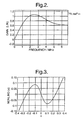
- the frequency response of the filter F 1 is shown in Figure 2.
- the filter contains a peak in the frequency response at about 2.5MHz (with a 13.5MHz sampling rate). This maximises the sensitivity to edge detail and reduces the sensitivity to noise.
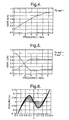
- the non-linearities used for EENR are based on those used on the Compatible Non-linear Pre-emphasis for MAC signals (IBA report 141/89). Although the curve represented here cannot be represented empirically, the following 'C' function uses a Newton-Raphson iteration to derive the two identical non-linearities N 1 & N 2 . The non-linear function resulting from the above iteration is shown in Figure 3. The slope of this function near the origin is greater than -1 to compensate for the losses in the cascaded response of filters F 1 & F 2 . For large amplitude signals the average slope is zero. Some harmonic distortions occurs at this point and in the preceding clip function C 1 which could alias down to DC and become visible, but this is removed by filter F 2 .
- the combined effect of the direct path and the HF path can produce summation signals at the output which exceed the range 0 to 1V. It is the purpose of C 2 is to limit the output range of this signal.
- the line delay L 1 has the effect of forming the recursive filter.
- the delay in L 1 is set to ensure that the delay round the loop C 3 , L 1 and the summation block constitute exactly one line. Every time the loop is traversed three-quarters of the delayed signal and half the signal from F 1 are added together. This produces a gain of two at zero vertical frequency.
- the clip function C 3 further reduces the signal amplitude around the recursive filter to about ⁇ 0.125V. This is the value required for the bias signal to reduce the effect of N 1 and N 2 to be near zero, and the inclusion of C3 in the feedback path prevents large amplitude edges from taking several lines to decay to insignificant levels in the recursive filter.
- the effect of the bias signal on combined non-linearity is shown in Figure 6.
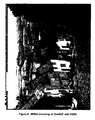
- Figures 7 and 8 show the level of improvement possible in this system.
- a picture 'Goldhill' which is 720x576 in resolution, has had a modest amount of source noise added to the source. This noise is slightly triangular (about +4dB lift at 4.5MHz).
- Figure 7 shows the effect of MPEG encoding the 'I' frame. The total sequence is at a bit rate of 3Mbits/s.
- DOT artefacts are visible in the picture.
- Figure 8 is the same picture at the same bit rate with EENR present in the chain. The amount of the DOT artefacts is less and more detail is visible as data capacity is not wasted on noise.
- EENR has been designed to operate in an MPEG I or II transmission system operating with constrained bit rates on picture material which has been originated from imperfect sources. In this situation, worthwhile improvements in picture quality are possible.
- EENR requires about 5000 gates to implement in ASIC or FPGA technology (excluding the line delay) and can be incorporated in an MPEG encoder with minimal changes to the existing design.
- Edge Enhanced Noise Reduction is a frequency dependent instantaneous compander system. It is applied only in the encoder both to Chrominance and luminance, and is best placed after the horizontal and vertical down sampling filters in the pre-processing stages of an encoder (not shown per se). High frequency, low level information (mainly noise) are reduced significantly in amplitude. In particular, EENR is designed to preserve edge details. In addition, a vertical recursive filter is used to prevent low level vertical information from being removed by the system. This is particularly useful in the luminance path. High level, high frequency components remain virtually unaffected. The system is 'transparent" to low frequency information.
- EENR has been designed to work in conjunction with MPEG encoding presented with source material which is slightly noisy and where the transmission bit rate is being constrained. It has been designed to provide minimal loss in picture quality due to the noise reduction process itself. It is not necessary to provide a complementary process in the receiver.
Landscapes
- Engineering & Computer Science (AREA)
- Multimedia (AREA)
- Signal Processing (AREA)
- Picture Signal Circuits (AREA)
- Compression Or Coding Systems Of Tv Signals (AREA)
- Image Processing (AREA)
- Measuring Pulse, Heart Rate, Blood Pressure Or Blood Flow (AREA)
- Traffic Control Systems (AREA)
- Tires In General (AREA)
- Vehicle Interior And Exterior Ornaments, Soundproofing, And Insulation (AREA)
- Compression Of Band Width Or Redundancy In Fax (AREA)
Claims (9)
- Ein Rauschverringerungssystem für ein Bildübertragungssystem, das eine erste Verzweigung und eine zweite Verzweigung, eine Filter-Vorrichtung (F1, F2) und eine Amplitudenbegrenzungs-Vorrichtung (N1, N2) in der zweiten Verzweigung zur Erzeugung eines Ausgangssignals für die zweite Verzweigung und eine Vorrichtung zum Kombinieren des Ausgangssignals der zweiten Verzweigung mit dem Signal der ersten Verzweigung umfasst, dadurch gekennzeichnet, dass
die Amplitudenbegrenzungs-Vorrichtung eine nichtlineare Amplitudenbegrenzungs-Vorrichtung ist, die Filter-Vorrichtung eine erste Filter-Vorrichtung (F1) und eine zweite Filter-Vorrichtung (F2) umfasst, wobei die erste und zweite Filter-Vorrichtung durch die nichtlineare Amplitudenbegrenzungs-Vorrichtung getrennt sind,
und einen rekursiven Filter, der zum Erzeugen eines Vorsignals angeordnet ist, um den Grad der Rauschverringerung, der auf Kanten mit niedriger Amplitude in dem Bild angelegt ist, zu reduzieren, indem die Eigenschaften der nichtlinearen Amplitudenbegrenzungs-Vorrichtung (N1, N2) angepasst werden. - System nach Anspruch 1, wobei der rekursive Filter eine Begrenzungs-Vorrichtung und eine Verzögerungsleitung umfasst, wobei ein Ausgang der Verzögerungsleitung an einen ersten Eingang einer Summier-Vorrichtung rückgekoppelt ist und ein zweiter Eingang der Summier-Vorrichtung so angeordnet ist, dass dieser ein beschnittenes Ausgangssignal der ersten Filter-Vorrichtung empfängt, wobei das Vorsignal zwischen der Begrenzungs-Vorrichtung und der Verzögerungsleitung erzeugt wird.
- System nach Anspruch 1 oder 2, wobei die Amplitudenbegrenzungs-Vorrichtung zwei im Wesentlichen identische Nichtlinearitäten (N1, N2) umfasst, die mittels einer Newton-Ralphson-Iteration abgeleitet sind.
- System nach einem der vorhergehenden Ansprüche, wobei es sich bei den Kanten um vertikale, horizontale oder diagonale Kantenelemente des Bildes handelt.
- System nach einem der vorhergehenden Ansprüche, wobei die erste und zweite Filter-Vorrichtung jeweils einen Hilbert-Transformationsfilter umfasst.
- System nach einem der vorhergehenden Ansprüche, wobei eine von der ersten und zweiten Filter-Vorrichtung ein Hilbert-Filter mit 6 Abgriffen ist und die andere Filter-Vorrichtung ein Hilbert-Filter mit 2 Abgriffen ist.
- System nach einem der vorhergehenden Ansprüche, wobei die erste und zweite Filter-Vorrichtung zusammen eine lineare Hochpass-Phasenfilterung erzeugen.
- Kodierer, der ein System enthält, wie in einem der vorhergehenden Ansprüche beansprucht.
- Kodierer, wie in Anspruch 8 beansprucht, in einem Videokompressionssystem.
Applications Claiming Priority (2)
| Application Number | Priority Date | Filing Date | Title |
|---|---|---|---|
| GB9600293 | 1996-01-08 | ||
| GBGB9600293.6A GB9600293D0 (en) | 1996-01-08 | 1996-01-08 | Improvements in or relating to noise reduction |
Publications (3)
| Publication Number | Publication Date |
|---|---|
| EP0783231A2 EP0783231A2 (de) | 1997-07-09 |
| EP0783231A3 EP0783231A3 (de) | 1998-09-09 |
| EP0783231B1 true EP0783231B1 (de) | 2002-10-09 |
Family
ID=10786736
Family Applications (1)
| Application Number | Title | Priority Date | Filing Date |
|---|---|---|---|
| EP96309282A Expired - Lifetime EP0783231B1 (de) | 1996-01-08 | 1996-12-19 | Bildrauschverringerungssystem |
Country Status (6)
| Country | Link |
|---|---|
| US (1) | US5974193A (de) |
| EP (1) | EP0783231B1 (de) |
| JP (1) | JPH1013717A (de) |
| AT (1) | ATE226002T1 (de) |
| DE (1) | DE69624213T2 (de) |
| GB (1) | GB9600293D0 (de) |
Families Citing this family (13)
| Publication number | Priority date | Publication date | Assignee | Title |
|---|---|---|---|---|
| US6069982A (en) * | 1997-12-23 | 2000-05-30 | Polaroid Corporation | Estimation of frequency dependence and grey-level dependence of noise in an image |
| KR100296596B1 (ko) * | 1999-07-14 | 2001-07-12 | 윤종용 | 4방향 일차원 고역 통과 필터링에 의한 윤곽선 강조 방법 |
| JP3619757B2 (ja) * | 2000-07-17 | 2005-02-16 | 三洋電機株式会社 | クリップ回路及びそれを用いた画像処理装置 |
| US6980598B2 (en) * | 2002-02-22 | 2005-12-27 | International Business Machines Corporation | Programmable vertical filter for video encoding |
| US6996186B2 (en) * | 2002-02-22 | 2006-02-07 | International Business Machines Corporation | Programmable horizontal filter with noise reduction and image scaling for video encoding system |
| FR2841423A1 (fr) * | 2002-06-25 | 2003-12-26 | Koninkl Philips Electronics Nv | Procede de detection d'artefacts de bloc |
| US7373013B2 (en) * | 2003-12-23 | 2008-05-13 | General Instrument Corporation | Directional video filters for locally adaptive spatial noise reduction |
| US7437013B2 (en) * | 2003-12-23 | 2008-10-14 | General Instrument Corporation | Directional spatial video noise reduction |
| US9679602B2 (en) | 2006-06-14 | 2017-06-13 | Seagate Technology Llc | Disc drive circuitry swap |
| US8269886B2 (en) * | 2007-01-05 | 2012-09-18 | Marvell World Trade Ltd. | Methods and systems for improving low-resolution video |
| US8885099B2 (en) * | 2007-02-16 | 2014-11-11 | Marvell World Trade Ltd. | Methods and systems for improving low resolution and low frame rate video |
| US9305590B2 (en) | 2007-10-16 | 2016-04-05 | Seagate Technology Llc | Prevent data storage device circuitry swap |
| EP2524505B1 (de) | 2010-01-15 | 2015-11-25 | Dolby Laboratories Licensing Corporation | Kantenverbesserung mittels metadaten bei zeitlicher skalierbarkeit |
Family Cites Families (13)
| Publication number | Priority date | Publication date | Assignee | Title |
|---|---|---|---|---|
| US5550789A (en) * | 1971-09-17 | 1996-08-27 | The United States Of America As Represented By The Secretary Of The Navy | Water turbulence detector |
| US3908114A (en) * | 1974-08-12 | 1975-09-23 | Rockwell International Corp | Digital Hilbert transformation system |
| KR890004220B1 (ko) * | 1984-06-30 | 1989-10-27 | 마쯔시다덴기산교 가부시기가이샤 | 영상신호 처리장치 |
| DE3530299A1 (de) * | 1985-08-26 | 1987-03-05 | Bosch Gmbh Robert | Schaltungsanordnung zur reduzierung des kantenrauschens bei der uebertragung von videosignalen |
| JPH0822022B2 (ja) * | 1987-02-13 | 1996-03-04 | 日本ビクター株式会社 | ノイズリデューサ |
| JPS63232578A (ja) * | 1987-03-19 | 1988-09-28 | Sony Corp | ノイズ低減回路 |
| GB8707533D0 (en) * | 1987-03-30 | 1987-05-07 | Indep Broadcasting Authority | Pre-emphasis for(mac)television signal |
| US5038388A (en) * | 1989-05-15 | 1991-08-06 | Polaroid Corporation | Method for adaptively sharpening electronic images |
| KR0171366B1 (ko) * | 1991-10-28 | 1999-03-20 | 강진구 | 자동화질 보상회로 |
| JP3097785B2 (ja) * | 1992-04-30 | 2000-10-10 | 株式会社リコー | 画像処理装置 |
| US5717789A (en) * | 1993-09-08 | 1998-02-10 | California Institute Of Technology | Image enhancement by non-linear extrapolation in frequency space |
| JP3359390B2 (ja) * | 1993-09-27 | 2002-12-24 | 株式会社リコー | 空間フィルタ装置 |
| DE69416584T2 (de) * | 1994-08-25 | 1999-10-07 | Co.Ri.M.Me. Consorzio Per La Ricerca Sulla Microelettronica Nel Mezzogiorno, Catania | Unscharfes Verfahren zur Bildrauschverringerung |
-
1996
- 1996-01-08 GB GBGB9600293.6A patent/GB9600293D0/en active Pending
- 1996-12-19 DE DE69624213T patent/DE69624213T2/de not_active Expired - Lifetime
- 1996-12-19 EP EP96309282A patent/EP0783231B1/de not_active Expired - Lifetime
- 1996-12-19 AT AT96309282T patent/ATE226002T1/de not_active IP Right Cessation
- 1996-12-20 US US08/777,715 patent/US5974193A/en not_active Expired - Lifetime
-
1997
- 1997-01-07 JP JP9031015A patent/JPH1013717A/ja active Pending
Also Published As
| Publication number | Publication date |
|---|---|
| EP0783231A3 (de) | 1998-09-09 |
| JPH1013717A (ja) | 1998-01-16 |
| DE69624213T2 (de) | 2003-07-10 |
| ATE226002T1 (de) | 2002-10-15 |
| DE69624213D1 (de) | 2002-11-14 |
| GB9600293D0 (en) | 1996-03-13 |
| US5974193A (en) | 1999-10-26 |
| EP0783231A2 (de) | 1997-07-09 |
Similar Documents
| Publication | Publication Date | Title |
|---|---|---|
| EP0783231B1 (de) | Bildrauschverringerungssystem | |
| US7177358B2 (en) | Picture coding apparatus, and picture coding method | |
| US5325125A (en) | Intra-frame filter for video compression systems | |
| KR100425640B1 (ko) | 비디오신호처리를위한노이즈추정및감소장치 | |
| EP0175736B1 (de) | Gerät das einen bewegungsdetektor umfasst, zur verarbeitung eines fernsehsignals | |
| KR100230860B1 (ko) | 비디오 신호 잡음 감소 시스템 | |
| US20040062316A1 (en) | Method for pre-suppressing noise of image | |
| Ojo et al. | An algorithm for integrated noise reduction and sharpness enhancement | |
| US5822005A (en) | Pre-oddification | |
| CN1029500C (zh) | 降低传输的视频值号的噪声的信号处理系统 | |
| US3938050A (en) | Non-linear correction of waveforms | |
| JPH0556306A (ja) | 適応形リンギング抑制装置 | |
| KR950009678B1 (ko) | 적응적 영상 부호화 장치 | |
| JP2001352546A (ja) | 高能率符号化における前処理装置 | |
| GB2435140A (en) | Compression of image data comprising regions of interest | |
| EP0587224B1 (de) | Empfänger für erweitertes Fernsehsignal | |
| KR0157897B1 (ko) | 디지탈 노치 필터 | |
| FI95638B (fi) | Kytkentäjärjestely televisiokuvan terävyyden korostamiseksi ja kohinan vaimentamiseksi | |
| JP2699582B2 (ja) | 輪郭補正器 | |
| GB2390772A (en) | Recursive combination of spatially co-sited video information from different temporal samples dependant on spatial frequency | |
| JP2001204025A (ja) | 高能率符号化装置 | |
| JP3991596B2 (ja) | 画像ディエンファシス復号化装置 | |
| EP0645936B1 (de) | Videosignalverarbeitung | |
| JP3149662B2 (ja) | 映像符号化装置及び映像復号化装置及び光ディスク | |
| JP2583877B2 (ja) | 雑音抑圧装置 |
Legal Events
| Date | Code | Title | Description |
|---|---|---|---|
| PUAI | Public reference made under article 153(3) epc to a published international application that has entered the european phase |
Free format text: ORIGINAL CODE: 0009012 |
|
| AK | Designated contracting states |
Kind code of ref document: A2 Designated state(s): AT DE FR GB IT NL |
|
| RAP1 | Party data changed (applicant data changed or rights of an application transferred) |
Owner name: NDS LIMITED |
|
| PUAL | Search report despatched |
Free format text: ORIGINAL CODE: 0009013 |
|
| AK | Designated contracting states |
Kind code of ref document: A3 Designated state(s): AT DE FR GB IT NL |
|
| 17P | Request for examination filed |
Effective date: 19990309 |
|
| RAP1 | Party data changed (applicant data changed or rights of an application transferred) |
Owner name: TANDBERG TELEVISION ASA |
|
| 17Q | First examination report despatched |
Effective date: 20010925 |
|
| GRAG | Despatch of communication of intention to grant |
Free format text: ORIGINAL CODE: EPIDOS AGRA |
|
| GRAG | Despatch of communication of intention to grant |
Free format text: ORIGINAL CODE: EPIDOS AGRA |
|
| GRAH | Despatch of communication of intention to grant a patent |
Free format text: ORIGINAL CODE: EPIDOS IGRA |
|
| GRAH | Despatch of communication of intention to grant a patent |
Free format text: ORIGINAL CODE: EPIDOS IGRA |
|
| GRAA | (expected) grant |
Free format text: ORIGINAL CODE: 0009210 |
|
| AK | Designated contracting states |
Kind code of ref document: B1 Designated state(s): AT DE FR GB IT NL |
|
| PG25 | Lapsed in a contracting state [announced via postgrant information from national office to epo] |
Ref country code: NL Free format text: LAPSE BECAUSE OF FAILURE TO SUBMIT A TRANSLATION OF THE DESCRIPTION OR TO PAY THE FEE WITHIN THE PRESCRIBED TIME-LIMIT Effective date: 20021009 Ref country code: IT Free format text: LAPSE BECAUSE OF FAILURE TO SUBMIT A TRANSLATION OF THE DESCRIPTION OR TO PAY THE FEE WITHIN THE PRESCRIBED TIME-LIMIT;WARNING: LAPSES OF ITALIAN PATENTS WITH EFFECTIVE DATE BEFORE 2007 MAY HAVE OCCURRED AT ANY TIME BEFORE 2007. THE CORRECT EFFECTIVE DATE MAY BE DIFFERENT FROM THE ONE RECORDED. Effective date: 20021009 Ref country code: AT Free format text: LAPSE BECAUSE OF FAILURE TO SUBMIT A TRANSLATION OF THE DESCRIPTION OR TO PAY THE FEE WITHIN THE PRESCRIBED TIME-LIMIT Effective date: 20021009 |
|
| REF | Corresponds to: |
Ref document number: 226002 Country of ref document: AT Date of ref document: 20021015 Kind code of ref document: T |
|
| REG | Reference to a national code |
Ref country code: GB Ref legal event code: FG4D |
|
| REF | Corresponds to: |
Ref document number: 69624213 Country of ref document: DE Date of ref document: 20021114 |
|
| ET | Fr: translation filed | ||
| NLV1 | Nl: lapsed or annulled due to failure to fulfill the requirements of art. 29p and 29m of the patents act | ||
| PLBE | No opposition filed within time limit |
Free format text: ORIGINAL CODE: 0009261 |
|
| STAA | Information on the status of an ep patent application or granted ep patent |
Free format text: STATUS: NO OPPOSITION FILED WITHIN TIME LIMIT |
|
| 26N | No opposition filed |
Effective date: 20030710 |
|
| REG | Reference to a national code |
Ref country code: GB Ref legal event code: 732E Free format text: REGISTERED BETWEEN 20090416 AND 20090422 |
|
| REG | Reference to a national code |
Ref country code: FR Ref legal event code: TP |
|
| PGFP | Annual fee paid to national office [announced via postgrant information from national office to epo] |
Ref country code: DE Payment date: 20131230 Year of fee payment: 18 Ref country code: GB Payment date: 20131227 Year of fee payment: 18 |
|
| PGFP | Annual fee paid to national office [announced via postgrant information from national office to epo] |
Ref country code: FR Payment date: 20131217 Year of fee payment: 18 |
|
| REG | Reference to a national code |
Ref country code: DE Ref legal event code: R119 Ref document number: 69624213 Country of ref document: DE |
|
| GBPC | Gb: european patent ceased through non-payment of renewal fee |
Effective date: 20141219 |
|
| REG | Reference to a national code |
Ref country code: FR Ref legal event code: ST Effective date: 20150831 |
|
| PG25 | Lapsed in a contracting state [announced via postgrant information from national office to epo] |
Ref country code: DE Free format text: LAPSE BECAUSE OF NON-PAYMENT OF DUE FEES Effective date: 20150701 Ref country code: GB Free format text: LAPSE BECAUSE OF NON-PAYMENT OF DUE FEES Effective date: 20141219 |
|
| PG25 | Lapsed in a contracting state [announced via postgrant information from national office to epo] |
Ref country code: FR Free format text: LAPSE BECAUSE OF NON-PAYMENT OF DUE FEES Effective date: 20141231 |