EP0783902A2 - Dispositif de contrÔle extracorporel pour un dispositif médical implantable - Google Patents
Dispositif de contrÔle extracorporel pour un dispositif médical implantable Download PDFInfo
- Publication number
- EP0783902A2 EP0783902A2 EP96250292A EP96250292A EP0783902A2 EP 0783902 A2 EP0783902 A2 EP 0783902A2 EP 96250292 A EP96250292 A EP 96250292A EP 96250292 A EP96250292 A EP 96250292A EP 0783902 A2 EP0783902 A2 EP 0783902A2
- Authority
- EP
- European Patent Office
- Prior art keywords
- signal
- transmission element
- pacemaker
- transmission
- behavior
- Prior art date
- Legal status (The legal status is an assumption and is not a legal conclusion. Google has not performed a legal analysis and makes no representation as to the accuracy of the status listed.)
- Granted
Links
Images
Classifications
-
- A—HUMAN NECESSITIES
- A61—MEDICAL OR VETERINARY SCIENCE; HYGIENE
- A61N—ELECTROTHERAPY; MAGNETOTHERAPY; RADIATION THERAPY; ULTRASOUND THERAPY
- A61N1/00—Electrotherapy; Circuits therefor
- A61N1/18—Applying electric currents by contact electrodes
- A61N1/32—Applying electric currents by contact electrodes alternating or intermittent currents
- A61N1/36—Applying electric currents by contact electrodes alternating or intermittent currents for stimulation
- A61N1/372—Arrangements in connection with the implantation of stimulators
- A61N1/37211—Means for communicating with stimulators
- A61N1/37235—Aspects of the external programmer
-
- A—HUMAN NECESSITIES
- A61—MEDICAL OR VETERINARY SCIENCE; HYGIENE
- A61N—ELECTROTHERAPY; MAGNETOTHERAPY; RADIATION THERAPY; ULTRASOUND THERAPY
- A61N1/00—Electrotherapy; Circuits therefor
- A61N1/18—Applying electric currents by contact electrodes
- A61N1/32—Applying electric currents by contact electrodes alternating or intermittent currents
- A61N1/38—Applying electric currents by contact electrodes alternating or intermittent currents for producing shock effects
- A61N1/39—Heart defibrillators
- A61N1/3925—Monitoring; Protecting
Definitions
- the invention relates to an extracorporeal device for use with an implantable medical device, in particular a pacemaker, defibrillator or cardioverter, according to the preamble of claim 1.
- the construction of a modern medical device which can be adapted to the individual conditions of a patient by means of a programming device usually allows signals to be recorded from inside the body.
- these can be signals which are to be transmitted as pure as possible from the measurement site, or signals which influence the operating behavior of the implantable device.
- These signals are influenced by signal transmission means which are provided within the processing part of the implantable device and are connected upstream or downstream of the telemetry stage.
- the action signals of the heart represented in the intracardiac EKG are recorded by an input filter provided for the normal operation of the pacemaker and then processed further. Due to the transmission properties of the input filter of the pacemaker, in particular due to the frequency response of the filter, the action signals of the heart are changed to a considerable extent, so that they do not allow a reliable diagnosis when evaluated in an EKG analysis device.
- a cardiac signal discriminator is known from DE-A-2 545 802 which serves to suppress interference signals which are detected simultaneously with the cardiac action signal.
- the cardiac signal discriminator has means by which the detected signals are rectified and attenuated at the same time.
- a digitally controlled amplitude control device for electrocardiographic signals is also known.
- the proposed control device has means which increase or decrease the transmission factor by one level each time a pulse signal (QRS complex) appears after comparing the signal amplitude with a threshold value.
- QRS complex pulse signal
- circuit arrangements known from the cited documents essentially relate to an adaptation of the amplitude of the intracardiac signals in order at least to limit the effectiveness of interference signals. This is necessary because the amplitude of these so-called artifacts often exceeds the cardiac useful signal by a hundred times.
- DD-A-295 995 describes a circuit arrangement for eliminating pacemaker pulse components from ECG leads, with which (surface) ECG signals can be freed from pacemaker pulse components by suitable filtering at the output of the EKG amplifier.
- DE-A-3 701 947 describes a method for acquiring a surface ECG, in which reliable processing of the cardiac action signals is also to be ensured for pacemaker wearers in that the operating parameters of the pacemaker are established by means of a wireless signal transmission device read out and then taken into account when processing the surface ECG.
- US Pat. No. 5,421,830 describes a programming system for a pacemaker or cardioverter / defibrillator with means for recording and analyzing an intracardially recorded heart signal, in which, in addition to means for storing and reproducing the heart signals, a simulation of the response of the implanted device to it is also simulated is provided.
- the known circuit arrangements do not solve the problem that the intracardiac EKG is distorted by the input filter of the pacemaker. It is therefore possible to transmit the intracardiac EKG to an extracorporeal control device via a telemetry transmitter for differentiated evaluation or storage.
- the diagnostic value of this intracardiac EKG as well as its usefulness for a possible simulation of the response of the pacemaker is greatly reduced by the signal-influencing effect of the input filter arranged in the pacemaker or possibly other transmission elements.
- the intracardiac EKG downstream of the point at which it was tapped for delivery to the telemetry unit is further influenced by amplifiers and filters before the signal of a detector device, such as a threshold value detector, which has been processed in this way is further processed. or a processing unit is supplied.
- the signal available on the extracorporeal device therefore differs from that in the pacemaker on Input of the detector or processing device present signal, so that the evaluation of the telemetrically transmitted signal does not allow a reliable statement about the detection or processing behavior of the pacemaker.
- the invention is therefore based on the object of providing an extracorporeal device for use with an implantable electromedical device which enables the most genuine possible provision and, if necessary, meaningful further processing of intracorporeally detected signals outside the body with regard to the function of the implanted device.
- the invention includes the technical teaching in the case of the extracorporeal device, on the one hand, to compensate for the signal influence caused by a transmission element located in front of the tapping point of the signal, for example the input filter of a pacemaker, in order to obtain an unadulterated signal, and, on the to the implanted device between the signal tapping point and the actual detector or the processing unit, the signal is influenced by amplifiers and filters simulate in order to be able to simulate the entire detection behavior of the implanted device externally.
- a transmission element located in front of the tapping point of the signal for example the input filter of a pacemaker
- the term "input signal” is to be understood in the following in a general sense:
- the invention is particularly advantageous for natural (spontaneous) heart action signals, i.e. applicable for external processing of intracardiac EKGs.
- body signals that reflect the activity of the pacemaker wearer, such as, for example, intrathoracically or intracardially detected impedance signals.
- it is not limited to this, but can in principle be used for all signals transmitted to the outside from the internal processing channel of an implanted device.
- the first transmission element arranged in the input channel is generally an input filter, which is designed, for example, as an anti-aliasing filter.
- the second transmission element usually consists of an amplifier with programmable amplification, which, by adjusting the amplification, enables the signal detector to be adapted to the electrical level of the input signal, or a correspondingly programmable amplifier filter module.
- the transmission elements can also consist of several individual components.
- Pacemakers with which versions of the device according to the invention can advantageously be used, have for transmitting the body signal (especially inracardial EKGs) to the outside of the body on a telemetry transmitter which is connected to the processing channel before the second transmission element and / or after the first transmission element.
- this telemetry transmitter is part of a telemetry unit of the pacemaker, which allows both transmitting and receiving mode, the signals recorded by the pacemaker being transmitted in the transmitting mode, while the receiving mode enables the pacemaker to be programmed by the extracorporeal control device.
- the signal is tapped for the telemetry transmitter either upstream or downstream of this transmission element.
- the pacemaker has two or more transmission elements (which is the rule in practice), the signal is tapped between the transmission elements.
- the device according to the invention has, in an embodiment tailored to implanted devices with signal tapping after a transmission link, downstream of the telemetry receiver, a third transmission link which has the task of compensating for the signal influence by the first transmission link upstream of the telemetry transmitter - as a rule the input filter. to provide the unadulterated input signal.
- This is particularly advantageous when recording and transmitting an intracardiac EKG as an input signal, since an unadulterated ECG has a much greater diagnostic value for the attending physician than that with known ones Control devices determined EKG signals distorted by the input filter of the pacemaker.
- the third transmission element therefore has, in particular, a transmission function which is exactly inverse with respect to the first transmission element in order to be able to compensate for its signal-influencing effect as completely as possible.
- the output signal AS (f) of the third transmission element with the complex transfer function c 3 (f) is then calculated from the telemetry signal TS (f) :
- AS ⁇ (f) c ⁇ 3rd (f) TS ⁇ (f)
- the signal appearing at the output of the transmission elements provided downstream of the tapping point differs from the telemetrically transmitted signal.
- a modeling of the pacemaker behavior is nevertheless made possible by the fact that the transfer function this link according to one aspect of the invention is also applied in the external device to the signal present there.
- the externally arranged third transmission element (this term in turn here may include several transmission elements provided in the extracorporeal device) in particular has exactly the same transmission function as the second transmission element arranged behind the telemetry transmitter.
- the provision of means for setting different transfer functions of the third transfer link enables the pacemaker behavior to be modeled for different settings of the second transfer link without having to reprogram the pacemaker itself.
- the second transmission element arranged in the cardiac pacemaker generally has a programmable amplifier which enables the downstream detector or processing device to be adapted to the level of the cardiac signals detected. This is important because the level of the cardiac signals sensed by the pacemaker depends on the position of the electrodes, the resistance of the body tissue and other factors and is therefore subject to fluctuations which have to be taken into account by adjusting the input gain.
- this setting is generally carried out by the attending doctor programming and programming various input amplifications in succession judged on the basis of sense markers or on the basis of the pacemaker behavior whether the pacemaker recognizes a signal delivered by the heart or not (“sensing test”).
- sensing test the input gain settings made during the test already affect the pacemaker behavior, which is often undesirable during the test. If the input sensitivity is too high, interfering signals are already incorrectly detected as heart actions, so that during the test there may be no stimulation per se. If, on the other hand, the input sensitivity is too low, the spontaneous cardiac actions are not detected and the pacemaker constantly stimulates during the test, even though the heart beats sufficiently fast.
- a further disadvantage of the previously known pacemaker systems is that the doctor generally sets a higher input sensitivity when programming the pacemaker than is actually required in order to be able to reliably detect a cardiac event even in the event of fluctuations in the intensity of the cardiac signals.
- the third transmission element is therefore followed by a detector device which has essentially the same detection behavior as that of the pacemaker.
- the transmission behavior of the third transmission element is adjustable in order to determine the transmission function that enables an optimal detection behavior.
- the setting is made in the extracorporeal device and not - as in known pacemaker systems - in the pacemaker itself, the pacemaker behavior is not influenced during the test. Only after the optimum setting has been determined is this telemetrically transmitted and set by the external device to the programmable pacemaker.
- the third transmission element preferably consists of a digital filter, the filter characteristics of which can be set by specifying a plurality of filter coefficients.
- the extracorporeal device can be used as a special control device for an implanted device (in particular a pacemaker, defibrillator and / or cardioverter), as a module of a programming device for such implanted devices or a body signal analysis device (such as an EKG or EEG device) or also be designed as an - in particular programmable - interface via which a conventional programming or analysis device can be connected to an implanted device in a substantially function-expanding manner.
- an implanted device in particular a pacemaker, defibrillator and / or cardioverter
- a body signal analysis device such as an EKG or EEG device
- a conventional programming or analysis device can be connected to an implanted device in a substantially function-expanding manner.
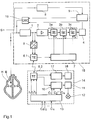
- FIG. 1 illustrates the structure of an extracorporeal control device 14 in cooperation with a programmable cardiac pacemaker 15.
- a programmable cardiac pacemaker 15 Of the two devices, only the modules related to the invention are shown; especially the conventional other components of a pacemaker are assumed to be known and are therefore not shown here.
- the shown pacemaker 15 works on the demand principle, i.e. it only sends stimulation impulses to the heart if the heart itself does not beat or does not beat sufficiently quickly.
- the pacemaker 15 therefore has an electrode E connected to the cardiac tissue H, which is connected to an anti-aliasing filter 1 for processing the input signal.
- this electrode is used to deliver stimulation pulses and is therefore additionally connected to the output of a pulse generator 16.
- the output signal of the anti-aliasing filter is fed to an amplifier 2, which amplifies the input signal by a factor of 32.
- the amplifier 2 is followed by a transmission element 3 with a plurality of filter elements 3a, 3b, 3c with adjustable cut-off frequencies f 1 , f 2 , f 2 , which by setting the Limit frequencies f 1 , f 2 , f 3 allow adaptation of the intracardially removed input signal to a downstream detector device 4. In this way, interference signals can be filtered out, which are recorded together with the heart signals via the electrode.
- the transmission element 3 has a plurality of control inputs via which the cut-off frequencies of the individual filter elements 3a, 3b, 3c can be set.
- the detector device 4 connected downstream of the transmission element 3 comprises as its main component a bipolar threshold value element which compares the amplified and filtered input signal with a positive and a negative threshold value and, in certain circumstances, detects a natural heartbeat when the positive threshold value is exceeded or the negative threshold value is undershot.
- the signal detector 4 additionally evaluates the time sequence and the duration of the threshold value violations in order to prevent incorrect detection when the signal level is shifted, for example due to an electrode shift in the body of the pacemaker wearer, with the result that the threshold value is permanently exceeded or undershot.
- the detector device 4 detects a natural heartbeat in the manner described above, this leads to an inhibition of the pulse generator 16, which otherwise stimulates with a predetermined stimulation frequency (see below). This means that the pulse generator 16 resets its internal clock generator and thus only emits a stimulation pulse if no further natural heartbeat is detected within a predetermined period of time after the detection.
- a body sensor S (shown here outside of the heart) is used to determine the stimulation frequency according to the patient's current hemodynamic requirement (which can be implemented, for example, as an intrathoracically arranged impedance measurement probe).
- Whose measurement signal is fed to an integrated amplifier and filter module 8, where signal processing takes place, and from there it arrives at a processing unit 9, which calculates the stimulation rate of the pacemaker and controls pulse generator 16 accordingly, likewise in a known manner, from the processed body signal.
- the pacemaker 15 enables the transmission of an intracardiac electrocardiogram (also referred to as "IECG”) and the signals from the body sensor S to an extracorporeal control device 14.
- IECG intracardiac electrocardiogram
- a two-channel analog / digital converter 5 is therefore connected to the input channel, which first converts the filtered input signal from the pacemaker and the measurement signal from the body sensor S into a digital data word, which is followed by digital data transmission to the extracorporeal Control device 14 allows.
- the pacemaker 15 has a telemetry unit 6.1, which enables both transmitting and receiving operation.
- transmission mode the IECG received via electrode E and / or the signal from body sensor S is transmitted to extracorporeal control device 14, while in reception mode Programming signals for setting the operating parameters of the pacemaker 15 are received.
- a programming option relates to the transfer function of the transfer element 3, which enables the detector device 4 to be adapted externally to the input signal received via the electrode by programming the desired transfer function.
- the extracorporeal control device 14 also has a telemetry unit 6.2 which enables the reception of the IECG and - in the transmission mode - the programming of the pacemaker 15.
- the extracorporeal control device 14 has a recursive digital filter system 10 of the second order, which enables filtering of the intracardiac EKG signal with a variable filter characteristic.
- the filter characteristic can be changed within wide limits by setting the filter coefficients c i .
- the output signal of this digital filter 10 is fed within the control device 14 to a detector or processing device 11 which has the same detection behavior as the detector device 4 located in the pacemaker 15.
- the control device 14 has a control unit 13, into which the attending physician enters the filter coefficients c i and thus determines the filter characteristics of the digital filter 10.
- the control unit 13 programs these filter coefficients c i into the digital filter 10 so that the attending physician can use the output signal of the detector device 11 to assess the effects of the filter settings on the detection behavior of the pacemaker.
- An indicator lamp 12 is shown in the figure as a means of checking the detection behavior, which indicates the detection of a cardiac action. In practice, of course, a refined preparation and also storage of the respective detection result will take place in order to be able to compare the effect of different filter settings.
- a filter and amplifier unit 17 is connected to the output of the second telemetry unit 6.2, to which the signal from the body sensor S (which is identified by coding in the transmission) is supplied by the telemetry unit.
- the transmission curve corresponds to that of module 8 in the pacemaker 15, so that the influencing of the body (eg impedance) signal in its signal processing path can also be simulated externally.
- a further display unit 18 is connected to the output of the filter and amplifier unit 17, on which the signal corresponding to the input signal of the processing unit 9 of the pacemaker can be displayed externally.
- Means for setting the transmission parameters of the assembly 8 are not shown in the figure, but can be provided and used in a similar manner to that described for the filter 10.
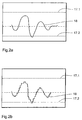
- FIG. 2b An exemplary signal curve for the output signal 19 of the digital filter 10 is shown in FIG. 2b.
- the threshold values of the downstream threshold element 11 are represented by horizontal dashed lines 17.1, 17.2. With this signal curve, the threshold value element 11 detects a cardiac event, since the lower threshold value 17.2 is not reached.
- the control unit 13 uses this to calculate which values of the cut-off frequencies f 1 , f 2 , f 3 are to be programmed, so that the second transmission element 3 located in the pacemaker 15 optimally reproduces this previously determined filter characteristic .
- the values determined in this way are then transmitted from the telemetry unit 6.2 to a control unit 7 located in the pacemaker 15, which adjusts the three filter elements 3a, 3b, 3c accordingly, so that the pacemaker 15 exhibits optimal detection behavior.
- a control unit 7 located in the pacemaker 15, which adjusts the three filter elements 3a, 3b, 3c accordingly, so that the pacemaker 15 exhibits optimal detection behavior.
- After programming these cut-off frequencies f 1 , f 2 , f 3 then shows the output signal of the second transmission element 3, the course 18 shown in FIG. 2a, which, apart from the lack of discretization, corresponds to the course shown in FIG. 2b, which is simulated by the extracorporeal control device 14.
- the embodiment of the invention is not limited to the preferred exemplary embodiments specified above. Rather, a number of variants are conceivable which make use of the solution shown, even in the case of fundamentally different types.
Landscapes
- Health & Medical Sciences (AREA)
- Radiology & Medical Imaging (AREA)
- Engineering & Computer Science (AREA)
- Biomedical Technology (AREA)
- Nuclear Medicine, Radiotherapy & Molecular Imaging (AREA)
- Life Sciences & Earth Sciences (AREA)
- Animal Behavior & Ethology (AREA)
- General Health & Medical Sciences (AREA)
- Public Health (AREA)
- Veterinary Medicine (AREA)
- Heart & Thoracic Surgery (AREA)
- Cardiology (AREA)
- Electrotherapy Devices (AREA)
Applications Claiming Priority (2)
| Application Number | Priority Date | Filing Date | Title |
|---|---|---|---|
| DE19548658A DE19548658A1 (de) | 1995-12-18 | 1995-12-18 | Extrakorporales Kontrollgerät für ein implantierbares medizinisches Gerät |
| DE19548658 | 1995-12-18 |
Publications (3)
| Publication Number | Publication Date |
|---|---|
| EP0783902A2 true EP0783902A2 (fr) | 1997-07-16 |
| EP0783902A3 EP0783902A3 (fr) | 1998-10-07 |
| EP0783902B1 EP0783902B1 (fr) | 2005-10-26 |
Family
ID=7781359
Family Applications (1)
| Application Number | Title | Priority Date | Filing Date |
|---|---|---|---|
| EP96250292A Expired - Lifetime EP0783902B1 (fr) | 1995-12-18 | 1996-12-17 | Dispositif de contrôle extracorporel pour un dispositif médical implantable |
Country Status (3)
| Country | Link |
|---|---|
| US (1) | US5792207A (fr) |
| EP (1) | EP0783902B1 (fr) |
| DE (2) | DE19548658A1 (fr) |
Cited By (2)
| Publication number | Priority date | Publication date | Assignee | Title |
|---|---|---|---|---|
| WO1999007354A3 (fr) * | 1997-08-08 | 1999-04-29 | Univ Duke | Compositions, dispositif et procedes facilitant les interventions chirurgicales |
| US6711436B1 (en) | 1997-08-08 | 2004-03-23 | Duke University | Compositions, apparatus and methods for facilitating surgical procedures |
Families Citing this family (23)
| Publication number | Priority date | Publication date | Assignee | Title |
|---|---|---|---|---|
| DE19758393B4 (de) * | 1997-12-23 | 2006-04-20 | Biotronik Meß- und Therapiegeräte GmbH & Co. Ingenieurbüro Berlin | Anordnung zur Patientenüberwachung |
| US6223083B1 (en) * | 1999-04-16 | 2001-04-24 | Medtronic, Inc. | Receiver employing digital filtering for use with an implantable medical device |
| US6718198B2 (en) | 1999-08-24 | 2004-04-06 | Cardiac Pacemakers, Inc. | Arrhythmia display |
| US6535763B1 (en) | 1999-08-22 | 2003-03-18 | Cardia Pacemakers, Inc. | Event marker alignment by inclusion of event marker transmission latency in the real-time data stream |
| US6650944B2 (en) | 2000-02-23 | 2003-11-18 | Medtronic, Inc. | Follow-up monitoring method and system for implantable medical devices |
| US8548576B2 (en) | 2000-12-15 | 2013-10-01 | Cardiac Pacemakers, Inc. | System and method for correlation of patient health information and implant device data |
| US6665558B2 (en) | 2000-12-15 | 2003-12-16 | Cardiac Pacemakers, Inc. | System and method for correlation of patient health information and implant device data |
| US6941169B2 (en) | 2001-06-04 | 2005-09-06 | Albert Einstein Healthcare Network | Cardiac stimulating apparatus having a blood clot filter and atrial pacer |
| US6823209B2 (en) * | 2001-10-19 | 2004-11-23 | Medtronic Physio-Control Corp. | Electrocardiogram filter |
| US7065409B2 (en) * | 2002-12-13 | 2006-06-20 | Cardiac Pacemakers, Inc. | Device communications of an implantable medical device and an external system |
| US7009511B2 (en) | 2002-12-17 | 2006-03-07 | Cardiac Pacemakers, Inc. | Repeater device for communications with an implantable medical device |
| US7395117B2 (en) * | 2002-12-23 | 2008-07-01 | Cardiac Pacemakers, Inc. | Implantable medical device having long-term wireless capabilities |
| US7127300B2 (en) | 2002-12-23 | 2006-10-24 | Cardiac Pacemakers, Inc. | Method and apparatus for enabling data communication between an implantable medical device and a patient management system |
| US6978182B2 (en) | 2002-12-27 | 2005-12-20 | Cardiac Pacemakers, Inc. | Advanced patient management system including interrogator/transceiver unit |
| US20040128161A1 (en) * | 2002-12-27 | 2004-07-01 | Mazar Scott T. | System and method for ad hoc communications with an implantable medical device |
| US7286872B2 (en) * | 2003-10-07 | 2007-10-23 | Cardiac Pacemakers, Inc. | Method and apparatus for managing data from multiple sensing channels |
| US7471980B2 (en) * | 2003-12-22 | 2008-12-30 | Cardiac Pacemakers, Inc. | Synchronizing continuous signals and discrete events for an implantable medical device |
| US7794499B2 (en) | 2004-06-08 | 2010-09-14 | Theken Disc, L.L.C. | Prosthetic intervertebral spinal disc with integral microprocessor |
| US8150509B2 (en) | 2004-10-21 | 2012-04-03 | Cardiac Pacemakers, Inc. | Systems and methods for drug therapy enhancement using expected pharmacodynamic models |
| US7545272B2 (en) | 2005-02-08 | 2009-06-09 | Therasense, Inc. | RF tag on test strips, test strip vials and boxes |
| US7752059B2 (en) * | 2005-07-05 | 2010-07-06 | Cardiac Pacemakers, Inc. | Optimization of timing for data collection and analysis in advanced patient management system |
| US8046060B2 (en) | 2005-11-14 | 2011-10-25 | Cardiac Pacemakers, Inc. | Differentiating arrhythmic events having different origins |
| US20090149839A1 (en) * | 2007-12-11 | 2009-06-11 | Hyde Roderick A | Treatment techniques using ingestible device |
Citations (5)
| Publication number | Priority date | Publication date | Assignee | Title |
|---|---|---|---|---|
| DE295995C (fr) | ||||
| DE2545802A1 (de) | 1975-10-13 | 1977-04-14 | Medtronic Inc | Herzsignaldiskriminator |
| EP0012709A1 (fr) | 1978-12-09 | 1980-06-25 | BIOTRONIK Mess- und Therapiegeräte GmbH & Co Ingenieurbüro Berlin | Circuit pour un signal électrocardiographique |
| DE3701947A1 (de) | 1987-01-23 | 1987-06-11 | Siemens Ag | Verfahren zur erfassung eines elektrokardiogramms (ekg) |
| US5421830A (en) | 1993-08-27 | 1995-06-06 | Pacesetter, Inc. | Programming system having means for recording and analyzing a patient's cardiac signal |
Family Cites Families (11)
| Publication number | Priority date | Publication date | Assignee | Title |
|---|---|---|---|---|
| DE3440615C1 (de) * | 1984-11-07 | 1986-04-10 | Institut für Rundfunktechnik GmbH, 8000 München | Verfahren zum Übertragen und Speichern von Tonsignalen und Einrichtung zur Durchführung des Verfahrens |
| DE3780013T2 (de) * | 1986-11-17 | 1993-01-21 | Alcatel Nv | Einstellbarer echokompensator. |
| US4757816A (en) * | 1987-01-30 | 1988-07-19 | Telectronics, N.V. | Telemetry system for implantable pacer |
| WO1989004192A1 (fr) * | 1987-11-13 | 1989-05-18 | Biotronik Mess- Und Therapiegeräte Gmbh & Co. Inge | Stimulateur cardiaque |
| DD295995A5 (de) * | 1990-06-27 | 1991-11-21 | Bezirkskrankenhaus "Friedrich Wolf" Chemnitz,De | Schaltungsanordnung zur eliminierung von herzschrittmacherimpulsanteilen aus elektrokardiografie-ableitungen |
| US5113869A (en) * | 1990-08-21 | 1992-05-19 | Telectronics Pacing Systems, Inc. | Implantable ambulatory electrocardiogram monitor |
| US5168871A (en) * | 1990-11-09 | 1992-12-08 | Medtronic, Inc. | Method and apparatus for processing quasi-transient telemetry signals in noisy environments |
| US5357969A (en) * | 1993-03-18 | 1994-10-25 | Hewlett-Packard Company | Method and apparatus for accurately displaying an ECG signal |
| US5411536A (en) * | 1993-06-03 | 1995-05-02 | Intermedics, Inc. | Method and apparatus for communicating data between medical devices to improve detectability of errors |
| DE4417927B4 (de) * | 1994-05-19 | 2005-02-03 | Biotronik Meß- und Therapiegeräte GmbH & Co. Ingenieurbüro Berlin | Telemetrievorrichtung, insbesondere für ein Gewebestimulator-System |
| US5466246A (en) * | 1994-07-29 | 1995-11-14 | Pacesetter, Inc. | Telemetry receiver for implantable device, incorporating digital signal processing |
-
1995
- 1995-12-18 DE DE19548658A patent/DE19548658A1/de not_active Ceased
-
1996
- 1996-12-17 DE DE59611286T patent/DE59611286D1/de not_active Expired - Lifetime
- 1996-12-17 EP EP96250292A patent/EP0783902B1/fr not_active Expired - Lifetime
- 1996-12-18 US US08/774,856 patent/US5792207A/en not_active Expired - Lifetime
Patent Citations (5)
| Publication number | Priority date | Publication date | Assignee | Title |
|---|---|---|---|---|
| DE295995C (fr) | ||||
| DE2545802A1 (de) | 1975-10-13 | 1977-04-14 | Medtronic Inc | Herzsignaldiskriminator |
| EP0012709A1 (fr) | 1978-12-09 | 1980-06-25 | BIOTRONIK Mess- und Therapiegeräte GmbH & Co Ingenieurbüro Berlin | Circuit pour un signal électrocardiographique |
| DE3701947A1 (de) | 1987-01-23 | 1987-06-11 | Siemens Ag | Verfahren zur erfassung eines elektrokardiogramms (ekg) |
| US5421830A (en) | 1993-08-27 | 1995-06-06 | Pacesetter, Inc. | Programming system having means for recording and analyzing a patient's cardiac signal |
Cited By (9)
| Publication number | Priority date | Publication date | Assignee | Title |
|---|---|---|---|---|
| WO1999007354A3 (fr) * | 1997-08-08 | 1999-04-29 | Univ Duke | Compositions, dispositif et procedes facilitant les interventions chirurgicales |
| US6043273A (en) * | 1997-08-08 | 2000-03-28 | Duke University | Compositions, apparatus and methods for facilitating surgical procedures |
| US6060454A (en) * | 1997-08-08 | 2000-05-09 | Duke University | Compositions, apparatus and methods for facilitating surgical procedures |
| US6087394A (en) * | 1997-08-08 | 2000-07-11 | Duke University | Compositions, apparatus and methods for facilitating surgical procedures |
| US6101412A (en) * | 1997-08-08 | 2000-08-08 | Duke University | Compositions, apparatus and methods for facilitating surgical procedures |
| US6127410A (en) * | 1997-08-08 | 2000-10-03 | Duke University | Compositions, apparatus and methods for facilitating surgical procedures |
| US6141589A (en) * | 1997-08-08 | 2000-10-31 | Duke University | Switch control for external pacing system |
| US6414018B1 (en) | 1997-08-08 | 2002-07-02 | Duke University | Compositions, apparatus and methods for facilitating surgical procedures |
| US6711436B1 (en) | 1997-08-08 | 2004-03-23 | Duke University | Compositions, apparatus and methods for facilitating surgical procedures |
Also Published As
| Publication number | Publication date |
|---|---|
| DE19548658A1 (de) | 1997-06-19 |
| DE59611286D1 (de) | 2005-12-01 |
| EP0783902A3 (fr) | 1998-10-07 |
| EP0783902B1 (fr) | 2005-10-26 |
| US5792207A (en) | 1998-08-11 |
Similar Documents
| Publication | Publication Date | Title |
|---|---|---|
| EP0783902B1 (fr) | Dispositif de contrôle extracorporel pour un dispositif médical implantable | |
| DE69330486T2 (de) | Herzzustandnachweis bei implantierbaren Vorrichtungen | |
| DE60315485T2 (de) | Vorrichtung zur detektion der r-welle des herzens in einer unterhaut-ekg-wellenform | |
| DE69315054T2 (de) | Verfahren und gerät zur überwachung von herztransplantat und zur eichung von analogen telemetrie | |
| EP0813891B1 (fr) | Détecteur de signaux | |
| DE60025486T2 (de) | Anpassbare evozierte herzreaktionsmessvorrichtung für automatische erregungsbestätigung | |
| DE69832639T2 (de) | Implantierbares Herzschrittmachersystem | |
| DE69727745T2 (de) | Herzschrittmacher mit Sicherheitsstimulation | |
| DE69632853T2 (de) | Herzschrittmacher mit automatischer Funktion für die Austastzeit | |
| DE68914891T2 (de) | Implantierbarer Herzschrittmacher mit automatischer Verstärkungssteuerung. | |
| DE60220751T2 (de) | Herzschrittmacher mit verbesserter Einfangsbestätigung | |
| DE60022714T2 (de) | Implantierbarer Herzschrittmacher | |
| DE3686713T2 (de) | System zur taktabhaengigen herzstimulierung. | |
| DE69710502T2 (de) | Gerät zur gewebestimulation | |
| DE69423674T2 (de) | Verfahren und Vorrichtung zur Uberwachung von Herzschrittmacherelektroden | |
| DE69226345T2 (de) | Erfassung der Bewegung zwischen einer Elektrode und einem Patienten und schnelle Wiederherstellung der Grenzen | |
| DE2322836A1 (de) | Ueberwachungsgeraet | |
| DE3428975A1 (de) | Atmungsgesteuerter herzschrittmacher | |
| EP0392032A1 (fr) | Appareil médical implantable comportant des moyens de transmission télémétrique de données | |
| EP0865802A2 (fr) | Appareil pour la détermination du délai AV | |
| EP0464252B1 (fr) | Dispositif de stimulation de tissus | |
| EP0215729A2 (fr) | Stimulateur cardiaque | |
| EP0215731B1 (fr) | Stimulateur cardiaque | |
| EP0216725A2 (fr) | Stimulateur cardiaque | |
| DE69729768T2 (de) | Herzschrittmacher mit Bestimmung des anaeroben Schwellwertes |
Legal Events
| Date | Code | Title | Description |
|---|---|---|---|
| PUAI | Public reference made under article 153(3) epc to a published international application that has entered the european phase |
Free format text: ORIGINAL CODE: 0009012 |
|
| AK | Designated contracting states |
Kind code of ref document: A2 Designated state(s): DE FR GB IT NL SE |
|
| PUAL | Search report despatched |
Free format text: ORIGINAL CODE: 0009013 |
|
| AK | Designated contracting states |
Kind code of ref document: A3 Designated state(s): DE FR GB IT NL SE |
|
| 17P | Request for examination filed |
Effective date: 19990218 |
|
| 17Q | First examination report despatched |
Effective date: 20030212 |
|
| GRAP | Despatch of communication of intention to grant a patent |
Free format text: ORIGINAL CODE: EPIDOSNIGR1 |
|
| GRAS | Grant fee paid |
Free format text: ORIGINAL CODE: EPIDOSNIGR3 |
|
| GRAA | (expected) grant |
Free format text: ORIGINAL CODE: 0009210 |
|
| AK | Designated contracting states |
Kind code of ref document: B1 Designated state(s): DE FR GB IT NL SE |
|
| REG | Reference to a national code |
Ref country code: GB Ref legal event code: FG4D Free format text: NOT ENGLISH |
|
| GBT | Gb: translation of ep patent filed (gb section 77(6)(a)/1977) |
Effective date: 20051026 |
|
| REF | Corresponds to: |
Ref document number: 59611286 Country of ref document: DE Date of ref document: 20051201 Kind code of ref document: P |
|
| REG | Reference to a national code |
Ref country code: SE Ref legal event code: TRGR |
|
| ET | Fr: translation filed | ||
| PLBE | No opposition filed within time limit |
Free format text: ORIGINAL CODE: 0009261 |
|
| STAA | Information on the status of an ep patent application or granted ep patent |
Free format text: STATUS: NO OPPOSITION FILED WITHIN TIME LIMIT |
|
| 26N | No opposition filed |
Effective date: 20060727 |
|
| PGFP | Annual fee paid to national office [announced via postgrant information from national office to epo] |
Ref country code: NL Payment date: 20081219 Year of fee payment: 13 |
|
| PGFP | Annual fee paid to national office [announced via postgrant information from national office to epo] |
Ref country code: IT Payment date: 20081223 Year of fee payment: 13 |
|
| REG | Reference to a national code |
Ref country code: NL Ref legal event code: V1 Effective date: 20100701 |
|
| PG25 | Lapsed in a contracting state [announced via postgrant information from national office to epo] |
Ref country code: NL Free format text: LAPSE BECAUSE OF NON-PAYMENT OF DUE FEES Effective date: 20100701 |
|
| PG25 | Lapsed in a contracting state [announced via postgrant information from national office to epo] |
Ref country code: IT Free format text: LAPSE BECAUSE OF NON-PAYMENT OF DUE FEES Effective date: 20091217 |
|
| REG | Reference to a national code |
Ref country code: DE Ref legal event code: R082 Ref document number: 59611286 Country of ref document: DE |
|
| REG | Reference to a national code |
Ref country code: DE Ref legal event code: R081 Ref document number: 59611286 Country of ref document: DE Owner name: BIOTRONIK SE & CO. KG, DE Free format text: FORMER OWNER: BIOTRONIK MESS- UND THERAPIEGERAETE GMBH & CO. INGENIEURBUERO BERLIN, 12359 BERLIN, DE Effective date: 20111219 |
|
| PGFP | Annual fee paid to national office [announced via postgrant information from national office to epo] |
Ref country code: DE Payment date: 20121121 Year of fee payment: 17 |
|
| PGFP | Annual fee paid to national office [announced via postgrant information from national office to epo] |
Ref country code: SE Payment date: 20121217 Year of fee payment: 17 Ref country code: GB Payment date: 20121218 Year of fee payment: 17 |
|
| PGFP | Annual fee paid to national office [announced via postgrant information from national office to epo] |
Ref country code: FR Payment date: 20130123 Year of fee payment: 17 |
|
| REG | Reference to a national code |
Ref country code: DE Ref legal event code: R119 Ref document number: 59611286 Country of ref document: DE |
|
| REG | Reference to a national code |
Ref country code: SE Ref legal event code: EUG |
|
| GBPC | Gb: european patent ceased through non-payment of renewal fee |
Effective date: 20131217 |
|
| PG25 | Lapsed in a contracting state [announced via postgrant information from national office to epo] |
Ref country code: SE Free format text: LAPSE BECAUSE OF NON-PAYMENT OF DUE FEES Effective date: 20131218 |
|
| REG | Reference to a national code |
Ref country code: FR Ref legal event code: ST Effective date: 20140829 |
|
| REG | Reference to a national code |
Ref country code: DE Ref legal event code: R119 Ref document number: 59611286 Country of ref document: DE Effective date: 20140701 |
|
| PG25 | Lapsed in a contracting state [announced via postgrant information from national office to epo] |
Ref country code: DE Free format text: LAPSE BECAUSE OF NON-PAYMENT OF DUE FEES Effective date: 20140701 |
|
| PG25 | Lapsed in a contracting state [announced via postgrant information from national office to epo] |
Ref country code: GB Free format text: LAPSE BECAUSE OF NON-PAYMENT OF DUE FEES Effective date: 20131217 Ref country code: FR Free format text: LAPSE BECAUSE OF NON-PAYMENT OF DUE FEES Effective date: 20131231 |