EP0783942A1 - Cisaille à bandes - Google Patents
Cisaille à bandes Download PDFInfo
- Publication number
- EP0783942A1 EP0783942A1 EP97850001A EP97850001A EP0783942A1 EP 0783942 A1 EP0783942 A1 EP 0783942A1 EP 97850001 A EP97850001 A EP 97850001A EP 97850001 A EP97850001 A EP 97850001A EP 0783942 A1 EP0783942 A1 EP 0783942A1
- Authority
- EP
- European Patent Office
- Prior art keywords
- arbors
- arbor
- slitter according
- frame portion
- slitter
- Prior art date
- Legal status (The legal status is an assumption and is not a legal conclusion. Google has not performed a legal analysis and makes no representation as to the accuracy of the status listed.)
- Withdrawn
Links
Images

Classifications
-
- B—PERFORMING OPERATIONS; TRANSPORTING
- B23—MACHINE TOOLS; METAL-WORKING NOT OTHERWISE PROVIDED FOR
- B23D—PLANING; SLOTTING; SHEARING; BROACHING; SAWING; FILING; SCRAPING; LIKE OPERATIONS FOR WORKING METAL BY REMOVING MATERIAL, NOT OTHERWISE PROVIDED FOR
- B23D35/00—Tools for shearing machines or shearing devices; Holders or chucks for shearing tools
- B23D35/008—Means for changing the cutting members
-
- B—PERFORMING OPERATIONS; TRANSPORTING
- B23—MACHINE TOOLS; METAL-WORKING NOT OTHERWISE PROVIDED FOR
- B23D—PLANING; SLOTTING; SHEARING; BROACHING; SAWING; FILING; SCRAPING; LIKE OPERATIONS FOR WORKING METAL BY REMOVING MATERIAL, NOT OTHERWISE PROVIDED FOR
- B23D19/00—Shearing machines or shearing devices cutting by rotary discs
- B23D19/04—Shearing machines or shearing devices cutting by rotary discs having rotary shearing discs arranged in co-operating pairs
- B23D19/06—Shearing machines or shearing devices cutting by rotary discs having rotary shearing discs arranged in co-operating pairs with several spaced pairs of shearing discs working simultaneously, e.g. for trimming or making strips
-
- B—PERFORMING OPERATIONS; TRANSPORTING
- B23—MACHINE TOOLS; METAL-WORKING NOT OTHERWISE PROVIDED FOR
- B23D—PLANING; SLOTTING; SHEARING; BROACHING; SAWING; FILING; SCRAPING; LIKE OPERATIONS FOR WORKING METAL BY REMOVING MATERIAL, NOT OTHERWISE PROVIDED FOR
- B23D35/00—Tools for shearing machines or shearing devices; Holders or chucks for shearing tools
- B23D35/002—Means for mounting the cutting members
- B23D35/004—Means for mounting the cutting members for circular cutting members
-
- B—PERFORMING OPERATIONS; TRANSPORTING
- B26—HAND CUTTING TOOLS; CUTTING; SEVERING
- B26D—CUTTING; DETAILS COMMON TO MACHINES FOR PERFORATING, PUNCHING, CUTTING-OUT, STAMPING-OUT OR SEVERING
- B26D7/00—Details of apparatus for cutting, cutting-out, stamping-out, punching, perforating, or severing by means other than cutting
- B26D7/26—Means for mounting or adjusting the cutting member; Means for adjusting the stroke of the cutting member
- B26D7/2614—Means for mounting the cutting member
- B26D7/2621—Means for mounting the cutting member for circular cutters
Definitions
- This invention relates to a cutter assembling means for slitting of material coils of relatively large width to one coil of
- the coil for slitting is favorably made of metal, for example steel and aluminum, but coils of other material can be used.
- the invention is useful for strong and thick material but also for weak and soft material.
- Slitting of coils of large width to one or several coils of desired width, often in connection with edge cutting is favorably performed in a cutter assembling means.
- a cutter assembling means Such means are described for instance in US-A-4183273 and EP 0 444 047 B1.
- the strip is directed in between two arbors equipped with dish shaped cutters and spacers.
- the arbors are mutually parallel disposed above each other and joined in bearings to two frame portions.
- a driving means for rotating the arbors In one end of the slitter is a driving means for rotating the arbors.
- one of the frame portions is revolving disposed sideways round a vertical shaft. But this means is often too weak. When slitting it will sometimes be forces, that is not directed in an imaginary plane through the longitudinal center lines of the two arbors. These forces will tilt the movable frame portion. The slitting operation will therefore not be sufficiently good.
- edges of strips When slitting the deflection of the arbors may not be allowed to be too big. In that case the edges of strips will not be sufficiently good, especially depending on that the plane surfaces of the cutters will be oblige angled in relation to each other. That will also cause that the edges will graze against each other . The edges will be damaged.
- the distance between the cutter edges respectively must be adjustable.
- the change of distance will be performed by moving one or both of the cooperating arbors vertically.
- the resilience will make that it will be difficult to adjust the distance and also keep the correct distance.
- a slitter, fig. 1, is used where slitting is executed between two arbors, 2, 3.
- the arbors, 2, 3, are equipped with cutters, 4, and intermediate spacers ,5.
- the width of the spacers, 5, corresponds to the width of the desired strips.
- the arbors , 2, 3, are fixed in the ends to two frame portions ,6,7.
- the driving of these arbors ,2,3, is made driving means containing a driving unit , 1, a gear reduction set, 8, and two universal driving shafts or Schmidt-engagements ,9, that are joined to the corresponding ends of the arbors, 2,3.
- the two frame portions, 6,7, of the slitters are advantageously joined together on the same base plate, 11.
- One of the frame portion ,6, will be quite stiff fixed to the base plate ,11.
- the other frame portion ,7, must be movable to expose the non driven end ,10, of the arbors ,2,3. It will make it easy to change the sets of cutters ,4, and spacers ,5.
- the movable frame portion ,7 is placed on two parallel guide rails, 13, that in turn are fixed to the plate, 11.
- the two parallel rail guides , 13, shall be mounted parallel to the center lines of the arbors 2,3, and in distance from each other. To get increased stability it will be very god to part them as much as possible.
- the top parts of the rail guides ,13 are fixed to the under side of the frame portion ,7. The play in the rail guides ,13, and the friction is negligible.
- the top part , 14, of the guide rail is namely parted from the bottom part, 15, by spheres.
- the transverse movement is made in the same way. After the front portion ,7, has been moved away from its ordinary place as far as the ends of the arbors are quite free it has a the same time entered a sledge ,16, that is movable perpendicular to the previous movement as far as it will be possible to dock a movable carriage to the ends of the arbors ,2,3.
- the sledge, 16, is in turn movable on rail guides, 17, that are fixed to the bottom plate, 11.
- the vertical position of at least one of the arbors 2, 3, must be adjustable to adjust the overlapping of the edges.
- the bearing housings ,24, of the adjustable arbors , 2,3, are guided by guides in the oblong windows of the frame portions ,6,7. Vertical rail guides are fitted to the vertical insides of the windows.
- the vertical position will continously be adjusted by hydraulic jacks below the bearinig housings ,24. They get the hydraulic power from a servomotor, that is adjusted by a microcomputer, getting impulses from level indicators.
- the set ,4,5, is fit to the arbor ,2,3, between a fixed ring ,19, and a movable hydraulic trust ring ,20.
- the fixed ring ,19, is seated at the driving end, 9, of the arbor ,2,3.
- the trust ring , 20, is axially movable and is similar to the outer cylinder of a jack.
- the piston ,21, of the jack is movable compared to the trust ring, 20.
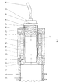
- the piston , 21 is a part of a collar , 22 , on a moreover cylindric sleeve , 23.
- the sleeve , 23, is movable and located on a holllow arbor ,25 , on the shaft ,12, of the arbor ,2,3.
- the roller bearings, 18, are fit to the mantle of the sleeve ,23.
- the bearings ,18 are joined to the movable frame portion ,6,7, by bearing housings.
- a hollow arbor, 25, that is a sleeve with an end part ,26, in the gable side.
- a hydraulic piston, 27 In this part ,26, is located a hydraulic piston, 27.
- the bore diameter shall with slip fit match the diameter of the shaft ,12.
- the outer surface of the hollow arbor , 25, is smaller tapered to a less diameter in the end part , 26.
- the inner surface of the sleeve ,23 is adjusted to be in contact to the outer surface of the hollow arbor , 25, but also allow some pushing up on the hollow arbor ,25.
- the pushing up of the sleeve ,25 is limited to the piston stroke of the hydraulic piston ,27, or of a fixed lip. The pushing up movement will also initiate a force between the shaft , 12, and the sleeve , 23.
- the location of bearings, 18, will also be at the same place on the arbor ,2,3.
- the first one , 29, is led to the trust ring, 20. It is also connected to a spring-loaded accumulator (not shown) to prevent fall of pressure depending on leakage.
- the second hole ,30 is connected to ring-shaped cut-in portions ,32, in the inner surface of the sleeve ,23.
- the third hole ,31 is connected to the hydraulic piston, 27, located at the end part , 26, of the hollow arbor, 25. All three holes , 29-31, are also separately connected to a turnable hydraulic oil connection ,33. The hydraulic oil is led to this connection from a force pump (not shown) by a flexible tube ,34.
Landscapes
- Engineering & Computer Science (AREA)
- Mechanical Engineering (AREA)
- Life Sciences & Earth Sciences (AREA)
- Forests & Forestry (AREA)
- Shearing Machines (AREA)
- Nonmetal Cutting Devices (AREA)
Priority Applications (2)
| Application Number | Priority Date | Filing Date | Title |
|---|---|---|---|
| CA 2210185 CA2210185A1 (fr) | 1997-01-09 | 1997-07-10 | Machine a refendre des bobines d'acier, d'aluminium et autres materiaux pour la production de bobines plus etroites |
| US08/890,860 US5924347A (en) | 1996-01-12 | 1997-07-10 | Splitting apparatus for splitting coils of metal such as steel and aluminum and coils of other materials into strips |
Applications Claiming Priority (4)
| Application Number | Priority Date | Filing Date | Title |
|---|---|---|---|
| SE9600098 | 1996-01-12 | ||
| SE9600098A SE505702C2 (sv) | 1996-01-12 | 1996-01-12 | Skärverk för band |
| SE9601839 | 1996-05-13 | ||
| SE9601839A SE510306C2 (sv) | 1996-01-12 | 1996-05-13 | Skärverk för band |
Publications (1)
| Publication Number | Publication Date |
|---|---|
| EP0783942A1 true EP0783942A1 (fr) | 1997-07-16 |
Family
ID=26662474
Family Applications (1)
| Application Number | Title | Priority Date | Filing Date |
|---|---|---|---|
| EP97850001A Withdrawn EP0783942A1 (fr) | 1996-01-12 | 1997-01-09 | Cisaille à bandes |
Country Status (2)
| Country | Link |
|---|---|
| EP (1) | EP0783942A1 (fr) |
| SE (1) | SE510306C2 (fr) |
Cited By (6)
| Publication number | Priority date | Publication date | Assignee | Title |
|---|---|---|---|---|
| US6010441A (en) * | 1997-10-27 | 2000-01-04 | Transman Ab | Device for handling and storing of cutters and spacers for a slitter which slits coils of material such as steel, aluminum or plastics |
| US6082238A (en) * | 1998-02-27 | 2000-07-04 | Asko, Inc. | Spacers in and for cutting devices |
| CN101804482A (zh) * | 2010-03-08 | 2010-08-18 | 北方工业大学 | 一种变宽度圆盘剪切机 |
| CN109807384A (zh) * | 2019-03-11 | 2019-05-28 | 苏州天钻机械设备有限公司 | 一种金属分切机 |
| CN111515634A (zh) * | 2020-06-06 | 2020-08-11 | 蔡锐军 | 一种铜带加工方法 |
| CN114799320A (zh) * | 2022-06-24 | 2022-07-29 | 南通市万帝来机电有限公司 | 一种用于风机制造的双盘式剪切装置 |
Citations (4)
| Publication number | Priority date | Publication date | Assignee | Title |
|---|---|---|---|---|
| DE2624875A1 (de) * | 1976-06-03 | 1977-12-08 | Dienes Werke | Streifenschneidmaschine |
| US4183273A (en) | 1978-04-10 | 1980-01-15 | Braner Enterprises, Inc. | Slitter having pivotal multiple spaced pairs of arbors |
| DE3835994A1 (de) * | 1987-10-30 | 1989-05-11 | Braner Inc | Laengsschneider |
| EP0444047B1 (fr) | 1988-09-21 | 1995-01-25 | Akv-Ortic Ab | Refendeuse amelioree |
-
1996
- 1996-05-13 SE SE9601839A patent/SE510306C2/sv unknown
-
1997
- 1997-01-09 EP EP97850001A patent/EP0783942A1/fr not_active Withdrawn
Patent Citations (4)
| Publication number | Priority date | Publication date | Assignee | Title |
|---|---|---|---|---|
| DE2624875A1 (de) * | 1976-06-03 | 1977-12-08 | Dienes Werke | Streifenschneidmaschine |
| US4183273A (en) | 1978-04-10 | 1980-01-15 | Braner Enterprises, Inc. | Slitter having pivotal multiple spaced pairs of arbors |
| DE3835994A1 (de) * | 1987-10-30 | 1989-05-11 | Braner Inc | Laengsschneider |
| EP0444047B1 (fr) | 1988-09-21 | 1995-01-25 | Akv-Ortic Ab | Refendeuse amelioree |
Cited By (7)
| Publication number | Priority date | Publication date | Assignee | Title |
|---|---|---|---|---|
| US6010441A (en) * | 1997-10-27 | 2000-01-04 | Transman Ab | Device for handling and storing of cutters and spacers for a slitter which slits coils of material such as steel, aluminum or plastics |
| US6082238A (en) * | 1998-02-27 | 2000-07-04 | Asko, Inc. | Spacers in and for cutting devices |
| CN101804482A (zh) * | 2010-03-08 | 2010-08-18 | 北方工业大学 | 一种变宽度圆盘剪切机 |
| CN109807384A (zh) * | 2019-03-11 | 2019-05-28 | 苏州天钻机械设备有限公司 | 一种金属分切机 |
| CN111515634A (zh) * | 2020-06-06 | 2020-08-11 | 蔡锐军 | 一种铜带加工方法 |
| CN111515634B (zh) * | 2020-06-06 | 2021-07-13 | 江苏扬铜新材料有限公司 | 一种铜带加工方法 |
| CN114799320A (zh) * | 2022-06-24 | 2022-07-29 | 南通市万帝来机电有限公司 | 一种用于风机制造的双盘式剪切装置 |
Also Published As
| Publication number | Publication date |
|---|---|
| SE9601839L (sv) | 1997-07-13 |
| SE510306C2 (sv) | 1999-05-10 |
| SE9601839D0 (sv) | 1996-05-13 |
Similar Documents
| Publication | Publication Date | Title |
|---|---|---|
| US4472880A (en) | Annular saw blade and annular saw | |
| CA1045355A (fr) | Tubes et constructions tubulaires connexes | |
| US8813622B2 (en) | Machine for slitting metal sheet | |
| EP0783942A1 (fr) | Cisaille à bandes | |
| US6295853B1 (en) | Spirally formed pipe cutter with driving mechanism to actively rotate inner knife | |
| US5924347A (en) | Splitting apparatus for splitting coils of metal such as steel and aluminum and coils of other materials into strips | |
| HK1249744A1 (en) | Placement apparatus for shaft body inserts | |
| JPH1133817A (ja) | ストリップ(帯状細片)切断機 | |
| CN120244450A (zh) | 一种建筑用钢管辅助焊接装置 | |
| FI65721B (fi) | Anordning foer foerskaerning av plaotband vid tillverkning av spiralslagna roer t ex foer ventilation | |
| CN221087645U (zh) | 一种连续加工的钢管自动切割机 | |
| CN220574605U (zh) | 弹簧转曲机 | |
| CA2210185A1 (fr) | Machine a refendre des bobines d'acier, d'aluminium et autres materiaux pour la production de bobines plus etroites | |
| CA2483307A1 (fr) | Appareil et procede de sciage de bobines | |
| CN217727465U (zh) | 全波长连续滚动超声焊接设备 | |
| KR19990008526A (ko) | 스트립용 슬리터 | |
| CN214604767U (zh) | 导管打孔限位板及打孔机 | |
| US3476000A (en) | Strip shearing apparatus | |
| CN1120988A (zh) | 杆、管或管坯切削加工的方法和设备 | |
| CN110586706A (zh) | U型肋生产系统及方法 | |
| US20020020274A1 (en) | Machine for cutting stacked sheet material and the like | |
| CN220787710U (zh) | 分条机中的夹紧装置 | |
| CN119216666B (zh) | 一种电机轴毛坯切割装置 | |
| CN219703647U (zh) | 一种带钢分条机组液压对中导向装置 | |
| KR850008633A (ko) | 회전금속 절삭공구 |
Legal Events
| Date | Code | Title | Description |
|---|---|---|---|
| PUAI | Public reference made under article 153(3) epc to a published international application that has entered the european phase |
Free format text: ORIGINAL CODE: 0009012 |
|
| AK | Designated contracting states |
Kind code of ref document: A1 Designated state(s): DE FI FR GB IT SE |
|
| 17P | Request for examination filed |
Effective date: 19980105 |
|
| STAA | Information on the status of an ep patent application or granted ep patent |
Free format text: STATUS: THE APPLICATION IS DEEMED TO BE WITHDRAWN |
|
| 18D | Application deemed to be withdrawn |
Effective date: 20010801 |