EP0783948A2 - Mehrkomponentenspritzgiessverfahren des typs "shuttle-stack" mit sequentieller injektion der komponenten - Google Patents
Mehrkomponentenspritzgiessverfahren des typs "shuttle-stack" mit sequentieller injektion der komponenten Download PDFInfo
- Publication number
- EP0783948A2 EP0783948A2 EP97102377A EP97102377A EP0783948A2 EP 0783948 A2 EP0783948 A2 EP 0783948A2 EP 97102377 A EP97102377 A EP 97102377A EP 97102377 A EP97102377 A EP 97102377A EP 0783948 A2 EP0783948 A2 EP 0783948A2
- Authority
- EP
- European Patent Office
- Prior art keywords
- mold cavity
- component
- adjustable mold
- product
- plastic material
- Prior art date
- Legal status (The legal status is an assumption and is not a legal conclusion. Google has not performed a legal analysis and makes no representation as to the accuracy of the status listed.)
- Granted
Links
Images
Classifications
-
- B—PERFORMING OPERATIONS; TRANSPORTING
- B29—WORKING OF PLASTICS; WORKING OF SUBSTANCES IN A PLASTIC STATE IN GENERAL
- B29C—SHAPING OR JOINING OF PLASTICS; SHAPING OF MATERIAL IN A PLASTIC STATE, NOT OTHERWISE PROVIDED FOR; AFTER-TREATMENT OF THE SHAPED PRODUCTS, e.g. REPAIRING
- B29C45/00—Injection moulding, i.e. forcing the required volume of moulding material through a nozzle into a closed mould; Apparatus therefor
- B29C45/03—Injection moulding apparatus
- B29C45/04—Injection moulding apparatus using movable moulds or mould halves
- B29C45/06—Injection moulding apparatus using movable moulds or mould halves mounted on a turntable, i.e. on a rotating support having a rotating axis parallel to the mould opening, closing or clamping direction
- B29C45/062—Injection moulding apparatus using movable moulds or mould halves mounted on a turntable, i.e. on a rotating support having a rotating axis parallel to the mould opening, closing or clamping direction carrying mould halves co-operating with fixed mould halves
-
- B—PERFORMING OPERATIONS; TRANSPORTING
- B29—WORKING OF PLASTICS; WORKING OF SUBSTANCES IN A PLASTIC STATE IN GENERAL
- B29C—SHAPING OR JOINING OF PLASTICS; SHAPING OF MATERIAL IN A PLASTIC STATE, NOT OTHERWISE PROVIDED FOR; AFTER-TREATMENT OF THE SHAPED PRODUCTS, e.g. REPAIRING
- B29C45/00—Injection moulding, i.e. forcing the required volume of moulding material through a nozzle into a closed mould; Apparatus therefor
- B29C45/03—Injection moulding apparatus
- B29C45/12—Injection moulding apparatus using two or more fixed moulds, e.g. in tandem
-
- B—PERFORMING OPERATIONS; TRANSPORTING
- B29—WORKING OF PLASTICS; WORKING OF SUBSTANCES IN A PLASTIC STATE IN GENERAL
- B29C—SHAPING OR JOINING OF PLASTICS; SHAPING OF MATERIAL IN A PLASTIC STATE, NOT OTHERWISE PROVIDED FOR; AFTER-TREATMENT OF THE SHAPED PRODUCTS, e.g. REPAIRING
- B29C45/00—Injection moulding, i.e. forcing the required volume of moulding material through a nozzle into a closed mould; Apparatus therefor
- B29C45/16—Making multilayered or multicoloured articles
- B29C45/1615—The materials being injected at different moulding stations
-
- B—PERFORMING OPERATIONS; TRANSPORTING
- B29—WORKING OF PLASTICS; WORKING OF SUBSTANCES IN A PLASTIC STATE IN GENERAL
- B29C—SHAPING OR JOINING OF PLASTICS; SHAPING OF MATERIAL IN A PLASTIC STATE, NOT OTHERWISE PROVIDED FOR; AFTER-TREATMENT OF THE SHAPED PRODUCTS, e.g. REPAIRING
- B29C45/00—Injection moulding, i.e. forcing the required volume of moulding material through a nozzle into a closed mould; Apparatus therefor
- B29C45/16—Making multilayered or multicoloured articles
- B29C45/1635—Making multilayered or multicoloured articles using displaceable mould parts, e.g. retractable partition between adjacent mould cavities
-
- B—PERFORMING OPERATIONS; TRANSPORTING
- B29—WORKING OF PLASTICS; WORKING OF SUBSTANCES IN A PLASTIC STATE IN GENERAL
- B29C—SHAPING OR JOINING OF PLASTICS; SHAPING OF MATERIAL IN A PLASTIC STATE, NOT OTHERWISE PROVIDED FOR; AFTER-TREATMENT OF THE SHAPED PRODUCTS, e.g. REPAIRING
- B29C45/00—Injection moulding, i.e. forcing the required volume of moulding material through a nozzle into a closed mould; Apparatus therefor
- B29C45/17—Component parts, details or accessories; Auxiliary operations
- B29C45/26—Moulds
- B29C45/32—Moulds having several axially spaced mould cavities, i.e. for making several separated articles
-
- B—PERFORMING OPERATIONS; TRANSPORTING
- B29—WORKING OF PLASTICS; WORKING OF SUBSTANCES IN A PLASTIC STATE IN GENERAL
- B29C—SHAPING OR JOINING OF PLASTICS; SHAPING OF MATERIAL IN A PLASTIC STATE, NOT OTHERWISE PROVIDED FOR; AFTER-TREATMENT OF THE SHAPED PRODUCTS, e.g. REPAIRING
- B29C45/00—Injection moulding, i.e. forcing the required volume of moulding material through a nozzle into a closed mould; Apparatus therefor
- B29C45/16—Making multilayered or multicoloured articles
- B29C45/1615—The materials being injected at different moulding stations
- B29C2045/1617—The materials being injected at different moulding stations using stack moulds
Definitions
- the present invention generally pertains to a method and an apparatus for multi-cavity injection molding of plastics products and is particularly directed to a highly efficient and highly controllable method and an apparatus for shuttle stack injection molding of multi-component plastic products.
- shuttle stack injection molding of multi-component plastic products was either carried out so that only two products were produced in each injection molding cycle, with the resulting low efficiency, or alternatively so that at least two mold cavities were filed at the same time by the same injection unit, giving rise to unbalanced filling of the cavities.
- the present invention enables production of four or more products in each production cycle while the filling of each cavity may be separate and therefore may be fully controlled.
- the present invention provides a method of cyclic injection molding a first multi-component plastic product and a second multi-component plastic product in an injection molding apparatus defining a right adjustable mold cavity and a left adjustable mold cavity, the method comprising the steps of: (a) adjusting the right adjustable mold cavity; (b) injecting plastic material into the right adjustable mold cavity to form a first component of the first multi-component product; (c) adjusting the left adjustable mold cavity; (d) injecting plastic material into the left adjustable mold cavity to form a second component of the second multi-component product which combines with a first component of the second multi-component product which was injected into the left adjustable mold cavity in step (i) of the previous cycle, to thereby cast said second multi-component product; (e) adjusting the right adjustable mold cavity; (f) injecting plastic material into the right adjustable mold cavity to form a second component of said first multi-component product, which combines with the first component of the first multi-component product which was injected into the right adjustable mold cavity in step (b
- the present invention also provides injection molding apparatus for cyclic injection molding a first multi-component plastic product and a second multi-component plastic product, said apparatus defining a right adjustable mold cavity and a left adjustable mold cavity, and said apparatus comprising means for adjusting the right adjustable mold cavity; means for adjusting the left adjustable mold cavity; a first injection unit for injecting plastic material into the right adjustable mold cavity to form a first component of the first multi-component product and for injecting plastic material into the left adjustable mold cavity to form a first component of a second multi-component product; a second injection unit for injecting plastic material into the right adjustable mold cavity subsequent to adjustment of the right adjustable mold cavity after formation of the first component of the first multi-component product, to form a second component of said first multi-component product, which combines with the first component of the first multi-component product to thereby cast said first multi-component product, and for injecting plastic material into the left adjustable mold cavity subsequent to adjustment of the left adjustable mold cavity after formation of the first component of the second multi-component product, to
- a second aspect of the present invention provides a method of cyclic injection molding a first multi-component plastic product and a second multi-component plastic product in an injection molding apparatus comprising a first injection unit, a second injection unit, a right adjustable mold cavity with a first movable barring means, a left adjustable mold cavity with a second movable barring means, and a clamping unit, the method comprising the steps of:
- a third aspect of the present invention provides a method of cyclic injection molding a first multi-component plastic product and a second multi-component plastic product in an injection molding apparatus comprising a first injection unit, a second injection unit, a common clamping unit, right, centre and left molding blocks for defining a right adjustable mold cavity between the right and centre molding blocks and a left adjustable mold cavity between the centre and left molding blocks, a first left runner system for leading plastic molding material from the first injection unit to the left adjustable mold cavity, a first right runner system for leading plastic molding material from the first injection unit to the right adjustable mold cavity, a second left runner system for leading plastic molding material from the second injection unit to the left adjustable mold cavity, a second right runner system for leading plastic molding material from the second injection on unit to the right adjustable mold cavity, the method comprising the steps of:
- a fourth aspect of the present invention provides an apparatus for cyclic injection molding a first multi-component plastic product and a second multi-component plastic product comprising a first injection unit, a second injection unit, a right adjustable mold cavity with a first movable barring means, a left adjustable mold cavity with a first movable barring means, a left adjustable mold cavity with a second movable barring means, and
- a fifth aspect of the present invention provides an apparatus for cyclic injection molding a first multi-component plastic product and a second multi-component plastic product comprising a first injection unit, a second injection unit, a common clamping unit, right, centre and left molding blocks for defining a right adjustable mold cavity between the right and centre molding blocks and a left adjustable mold cavity between the right and centre molding blocks and a left adjustable mold cavity between the centre and left molding blocks, the centre block comprising a first left runner system for leading plastic molding material from the first injection unit to the left adjustable mold cavity, a first right runner system for leading plastic molding material from the first injection unit to the right adjustable mold cavity, a second left runner system for leading plastic molding material from the second injection unit to the left adjustable mold cavity, a second right runner system for leading plastic molding material from the second injection unit to the right adjustable mold cavity, and
- a sixth aspect of the present invention provides a method of cyclic injection molding a multi-component product in an injection molding system comprising a mold positioning system, a first injection system and a second injection system, and a left molding block, a right molding block and an intermediate molding block located between the left and the right molding blocks, said blocks being disposed for axial movement in respect to each other,
- step (g) comprises the step of (n) combining by the mold positioning system said molding blocks so that a second left general mold cavity part is connected with the first left gated mold cavity part to form a third left mold cavity
- step (h) comprises the step of (o) injecting by the first injection system via the first runner system first fluid plastic material into the third left mold cavity, and solidifying the material to produce a second left plastic component
- step (i) comprises the step of (p) separating by the mold positions system the right and centre molding blocks
- step (j) comprises the step of (q) combining by the mold positioning system said molding blocks so that a second right general mold cavity part is connected with the first right gated mold cavity part to form a third right mold cavity
- step (k) comprises the step of (r) injecting by the first injection system
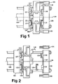
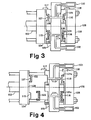
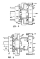
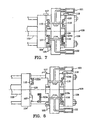
- Figures 1 through 8 show within a cycle four chronological top sectional views of an injection molding system used for operating the cyclical method of the invention.
- the injection molding system comprises a mold positioning system 103 being a standard clamping unit and a left and a right locking means 117,118 for locking the left molding block 104 together with the intermediate molding block 105 or for locking the right molding block 106 together with the intermediate molding block 105 respectively.
- a left molding block 104, a right molding block 106, and an intermediate molding block 105, located between the left and the right molding blocks 104,106 are disposed for axial movement in respect to each other.
- the left molding block 104 defines a first left general mold cavity part 107, a second left general mold cavity part 115 and the intermediate molding block 105 defines a first left gated mold cavity part 108 and a second left gated mold cavity part 109.
- the right molding block 106 defines a first right general mold cavity part 110, a second right general mold cavity part 116 and the intermediate molding block defines a first right gated mold cavity part 111 and a second right gated mold cavity part 112.
- the intermediate molding block 105 defines a first runner system 113 connected to the first left gated mold cavity part and the first right gated mold cavity part 108,111 and further defines a second runner system 114 connected to the second left gated mold cavity part and the second right gated mold cavity part 109,112.
- the method comprises the following steps:
- Figure 1 Combining by the mold positioning system 103 the molding blocks 104,105,106 so that the first left general mold cavity part 107 is connected with the first left gated mold cavity part 8 to form a first left mold cavity 119 and so that the second left general mold cavity part 115 is connected with the second left gated mold cavity part 109 to form a fourth left mold cavity 120, which encompasses a left plastic component 121 formed in the previous production cycle.
- Figure 3 Injecting by the first injection system 101 via the first runner system 113 first fluid plastic material into the first right mold cavity 129, and solidifying the material to produce a first right plastic component 124a and approximately at the same time injecting by the second injection system 102 via the second runner system 114 second fluid plastic material into the fourth right mold cavity 130 so that the second fluid plastic is united with the second right plastic component 124 and solidifying the material to mold a second right multi-component plastic product 125a.
- Rotating revolvable section 126 of the left molding block 104 pivoting around the centre axis 128 of the injection molding by the mold positioning system 103 molding blocks 104,105,106 so that the first left general mold cavity part 107 is connected with the second left gated mold cavity part 109 to form a second left mold cavity 132 which encompasses the first left plastic component 122, and so that the second left general mold cavity part 115 is connected with the first left gated mold cavity part 108 to form a third left mold cavity 131.
- Figure 7 Injecting by the first injection system 101 via the first runner system 103 first fluid plastic material into the third right mold cavity 133, and solidifying the material to produce a second right plastic component 124b and approximately at the same time injecting by the second injection system 102 via the second runner system 114 second fluid plastic material into the second right mold cavity 134 so that the second fluid plastic is united with the first right plastic component 124a and solidifying the material to mold a first right multi-component plastic product 125b.
- Figure 8 While locking together the right and intermediate molding blocks 106,105 by the right locking means 118, separating by the mold positioning system 103 to the left and intermediate molding blocks 104,105 and retaining the second left plastic component 122a on the second left general mold cavity part 115, and ejecting the first left product 23a.
- the molding blocks may be operated in such a fashion that two stack-molds are disposed for axial movement in respect to each other.
- the injection units may be placed in many different constellations, vertically, horizontally, along the machine axis or perpendicular thereto, or different angles altogether.
- the injection units will normally have to be separated from the intermediate molding block at some period of the production cycle, but it is possible to operate the invention with the injection units attached to the intermediate molding block.
- the opening and closing periods may be different from the preferred embodiment, it is, for example, possible for the left side to open two or three times every time the right side opens once. It is possible to produce a different product in the left side and the right side, as, for example, a container and a lid both needing two barrier materials for such properties as moisture, oxygen, carbon dioxide, solutions, and air, for products such as foods, carbonated drinks, paints and vacuumated blood tubes.
- the runner systems may consist of forked or unconnected sections or sections separated by valves of many types. It may be useful to include a controlled valve near or at the gate to each product, although this feature is optional. To start up the system without such valves, either double material is injected the first time or a previously produced product is inserted in half of the mold cavities.
- the extra general mold cavity part may be used as a separate station for printing or in line blow molding or the like.
Landscapes
- Engineering & Computer Science (AREA)
- Manufacturing & Machinery (AREA)
- Mechanical Engineering (AREA)
- Moulds For Moulding Plastics Or The Like (AREA)
- Injection Moulding Of Plastics Or The Like (AREA)
Applications Claiming Priority (5)
| Application Number | Priority Date | Filing Date | Title |
|---|---|---|---|
| US07/394,228 US5030406A (en) | 1989-08-14 | 1989-08-14 | Sequentially injected multi-component shuttle-stack-molding |
| US394228 | 1989-08-14 | ||
| US539855 | 1990-06-18 | ||
| US07/539,855 US5049343A (en) | 1990-06-18 | 1990-06-18 | Sequentially injected multi-component core-back injection molding |
| EP90913311A EP0487625B1 (de) | 1989-08-14 | 1990-08-13 | Nacheinander eingespritzte mehrkomponente einspritzgiessverfahren |
Related Parent Applications (2)
| Application Number | Title | Priority Date | Filing Date |
|---|---|---|---|
| EP90913311A Division EP0487625B1 (de) | 1989-08-14 | 1990-08-13 | Nacheinander eingespritzte mehrkomponente einspritzgiessverfahren |
| EP90913311.8 Division | 1991-03-13 |
Publications (3)
| Publication Number | Publication Date |
|---|---|
| EP0783948A2 true EP0783948A2 (de) | 1997-07-16 |
| EP0783948A3 EP0783948A3 (de) | 1998-06-10 |
| EP0783948B1 EP0783948B1 (de) | 2001-10-17 |
Family
ID=27014647
Family Applications (2)
| Application Number | Title | Priority Date | Filing Date |
|---|---|---|---|
| EP97102377A Expired - Lifetime EP0783948B1 (de) | 1989-08-14 | 1990-08-13 | Mehrkomponentenspritzgiessverfahren des Typs "Shuttle-Stack" mit sequentieller Injektion der Komponenten |
| EP90913311A Expired - Lifetime EP0487625B1 (de) | 1989-08-14 | 1990-08-13 | Nacheinander eingespritzte mehrkomponente einspritzgiessverfahren |
Family Applications After (1)
| Application Number | Title | Priority Date | Filing Date |
|---|---|---|---|
| EP90913311A Expired - Lifetime EP0487625B1 (de) | 1989-08-14 | 1990-08-13 | Nacheinander eingespritzte mehrkomponente einspritzgiessverfahren |
Country Status (5)
| Country | Link |
|---|---|
| EP (2) | EP0783948B1 (de) |
| JP (1) | JP2875021B2 (de) |
| CA (1) | CA2064823C (de) |
| DE (2) | DE69031564T2 (de) |
| WO (1) | WO1991002640A1 (de) |
Cited By (2)
| Publication number | Priority date | Publication date | Assignee | Title |
|---|---|---|---|---|
| DE112010003508T5 (de) | 2009-09-01 | 2012-10-25 | Dbm Reflex Enterprises Inc. | Vielfarbenfahrzeuglinse mit wechselseitig verbundenen TIR-Reflexionsprismen |
| CN104972599A (zh) * | 2015-06-15 | 2015-10-14 | 苏州千裕电子科技有限公司 | 一种灯罩注塑工艺 |
Families Citing this family (17)
| Publication number | Priority date | Publication date | Assignee | Title |
|---|---|---|---|---|
| US5618065A (en) * | 1994-07-21 | 1997-04-08 | Hitachi Metals, Ltd. | Electric welding pipe joint having a two layer outer member |
| US5916468A (en) * | 1996-07-08 | 1999-06-29 | Hitachi Metals Ltd. | Electrically weldable pipe joint and production method thereof |
| EP1027199A1 (de) | 1997-02-25 | 2000-08-16 | Jes Tougaard Gram | Verfahren und maschine zum mulitkomponentenformen |
| DE20017737U1 (de) * | 2000-10-16 | 2000-12-21 | Braun Formenbau GmbH, 79353 Bahlingen | Etagenwerkzeug zum Spritzgießen von Kunststoffteilen |
| JP4187168B2 (ja) * | 2003-06-12 | 2008-11-26 | 東洋ゴム工業株式会社 | 二層構造ブッシュの成形金型 |
| WO2004110722A1 (ja) * | 2003-06-12 | 2004-12-23 | Toyo Tire & Rubber Co., Ltd. | 二層構造ブッシュの製造方法及び装置 |
| AU2003242362A1 (en) * | 2003-06-12 | 2005-01-04 | Toyo Tire And Rubber Co., Ltd. | Metal mold for molding bush of double-layer structure |
| USD574473S1 (en) | 2007-09-12 | 2008-08-05 | Dehco, Inc. | Bath unit |
| USD577425S1 (en) | 2007-10-24 | 2008-09-23 | Dehco, Inc. | Shower unit |
| JP4434276B2 (ja) | 2007-12-11 | 2010-03-17 | 株式会社デンソー | 2色成形方法 |
| KR101092636B1 (ko) | 2009-10-07 | 2012-01-10 | 재영솔루텍 주식회사 | 다중 금형, 이를 포함하는 사출 성형 어셈블리 |
| DE102014011135B4 (de) * | 2014-07-25 | 2019-11-07 | Quin Gmbh | Verfahren und Vorrichtung zur Herstellung eines Dekorteils |
| JP6441274B2 (ja) * | 2016-08-23 | 2018-12-19 | 株式会社名機製作所 | 金型回転式射出成形機および金型回転式射出機の作動方法 |
| JP6441271B2 (ja) | 2016-08-23 | 2018-12-19 | 株式会社名機製作所 | 金型回転式射出成形機および金型回転式射出成形機の金型交換方法 |
| JP6878217B2 (ja) * | 2017-09-08 | 2021-05-26 | 株式会社ミツバ | 射出成形金型 |
| CN111825431B (zh) * | 2020-05-20 | 2023-02-07 | 中国工程物理研究院材料研究所 | 一种复合材料的高通量一体化制备方法 |
| CN118700446B (zh) * | 2024-07-17 | 2024-12-20 | 太仓图峰精密模具有限公司 | 一种便于上下料的汽车灯罩注塑成型模具 |
Family Cites Families (11)
| Publication number | Priority date | Publication date | Assignee | Title |
|---|---|---|---|---|
| GB1061234A (en) * | 1964-05-11 | 1967-03-08 | Hehl & Soehne Arburg Masch | Moulds for injection moulding machines |
| ES455627A1 (es) | 1977-01-26 | 1978-01-01 | Mares Ibanez Pedro | Perfeccionamientos en la fabricacion de piezas inyectadas demateriales plasticos de estructura compuesta. |
| DE3037252C2 (de) * | 1980-10-02 | 1983-12-29 | Wilhelm Rogg Kunststoff-Metallisierung, 8500 Nürnberg | Spritzgießform zum Herstellen von Formkörpern aus zwei Kunststoffarten |
| US4400341A (en) * | 1980-10-14 | 1983-08-23 | Universal Commerce And Finance N.V. | Injection molding of thermoplastics in sandwich mold employing desynchronized opening, extended and closing periods |
| EP0103363B1 (de) * | 1982-07-15 | 1986-11-26 | SORENSEN, Jens Ole | Asynchroner Mehretagen-Spritzguss |
| JPS5973930A (ja) * | 1982-10-22 | 1984-04-26 | Mitsubishi Rayon Co Ltd | 合成樹脂成形品の製造方法 |
| JPH0657417B2 (ja) * | 1985-11-15 | 1994-08-03 | ティーディーケイ株式会社 | 成形金型 |
| JP2519947B2 (ja) * | 1987-07-31 | 1996-07-31 | 大下産業株式会社 | 組立成形部材の製造方法 |
| US4784285A (en) * | 1987-08-03 | 1988-11-15 | Chemcast Corporation | Dual durometer self locking and sealing plugs and method for making same |
| US4935184A (en) | 1988-02-05 | 1990-06-19 | Primtec | Stabilized injection molding when using a common mold part with separate complimentary mold parts |
| JP6119407B2 (ja) | 2013-05-02 | 2017-04-26 | 富士通株式会社 | 情報処理装置、情報処理方法、及び情報処理プログラム |
-
1990
- 1990-08-13 JP JP2512504A patent/JP2875021B2/ja not_active Expired - Fee Related
- 1990-08-13 EP EP97102377A patent/EP0783948B1/de not_active Expired - Lifetime
- 1990-08-13 WO PCT/US1990/004566 patent/WO1991002640A1/en not_active Ceased
- 1990-08-13 CA CA002064823A patent/CA2064823C/en not_active Expired - Fee Related
- 1990-08-13 DE DE69031564T patent/DE69031564T2/de not_active Expired - Fee Related
- 1990-08-13 DE DE1990633832 patent/DE69033832T2/de not_active Expired - Fee Related
- 1990-08-13 EP EP90913311A patent/EP0487625B1/de not_active Expired - Lifetime
Cited By (4)
| Publication number | Priority date | Publication date | Assignee | Title |
|---|---|---|---|---|
| DE112010003508T5 (de) | 2009-09-01 | 2012-10-25 | Dbm Reflex Enterprises Inc. | Vielfarbenfahrzeuglinse mit wechselseitig verbundenen TIR-Reflexionsprismen |
| DE112010003508B4 (de) | 2009-09-01 | 2022-02-03 | Dbm Reflex Enterprises Inc. | Vielfarbenfahrzeuglinse mit wechselseitig verbundenen TIR-Reflexionsprismen und Spritzgussvorrichtung |
| CN104972599A (zh) * | 2015-06-15 | 2015-10-14 | 苏州千裕电子科技有限公司 | 一种灯罩注塑工艺 |
| CN104972599B (zh) * | 2015-06-15 | 2017-12-12 | 苏州千裕电子科技有限公司 | 一种灯罩注塑工艺 |
Also Published As
| Publication number | Publication date |
|---|---|
| DE69033832D1 (de) | 2001-11-22 |
| EP0783948A3 (de) | 1998-06-10 |
| JP2875021B2 (ja) | 1999-03-24 |
| EP0783948B1 (de) | 2001-10-17 |
| JPH10502022A (ja) | 1998-02-24 |
| CA2064823A1 (en) | 1991-02-15 |
| EP0487625B1 (de) | 1997-10-08 |
| WO1991002640A1 (en) | 1991-03-07 |
| DE69031564T2 (de) | 1998-02-12 |
| EP0487625A4 (en) | 1993-12-29 |
| DE69031564D1 (de) | 1997-11-13 |
| CA2064823C (en) | 2000-11-07 |
| EP0487625A1 (de) | 1992-06-03 |
| DE69033832T2 (de) | 2002-06-06 |
Similar Documents
| Publication | Publication Date | Title |
|---|---|---|
| US5030406A (en) | Sequentially injected multi-component shuttle-stack-molding | |
| EP0783948B1 (de) | Mehrkomponentenspritzgiessverfahren des Typs "Shuttle-Stack" mit sequentieller Injektion der Komponenten | |
| CA1273765A (en) | Injection-molding machine having at least two plasticising and injecting units | |
| AU591385B2 (en) | Injection moulding apparatus | |
| US5049343A (en) | Sequentially injected multi-component core-back injection molding | |
| US6447280B1 (en) | Dual manifold mold with rotating center plate | |
| CA2247867A1 (en) | Multiple gating nozzle | |
| CA2065856A1 (en) | Method for the use of gas assistance in the molding of plastic articles | |
| CA2240085A1 (en) | Sequential fill valve gated injection molding system | |
| CA2242967A1 (en) | Electrically-operated injection molding machine and injection molding method using the relevant machine | |
| US5200127A (en) | Method and apparatus for gas assisted injection molding | |
| US4165959A (en) | Apparatus for injection-moulding several moulding materials onto one another | |
| JPH04505294A (ja) | 射出成形により溶融樹脂から中空体を作る方法とシステム | |
| US5609894A (en) | Injection molding apparatus for producing plastic lids | |
| US4077760A (en) | Injection molding process and apparatus | |
| US4971747A (en) | Hold pressurization by confining runner systems of adjustable feed system in multiple reciprocal stack molding system | |
| US6231805B1 (en) | Injection molding method | |
| US4128613A (en) | Injection molding method | |
| EP0103363A1 (de) | Asynchroner Mehretagen-Spritzguss | |
| EP0785060A3 (de) | Verfahren zum Spritzgiessen von Werkstücken | |
| US5641446A (en) | Method of producing tag pin assembly | |
| JP3749836B2 (ja) | 複合成形品の射出成形方法および射出成形用金型 | |
| GB2297711A (en) | Method and apparatus for manufacturing sealing closure and insert | |
| JPH06285912A (ja) | 新規な複合射出成形装置 | |
| KR20000000445A (ko) | 선단부에 다수의 게이트를 가지는 사출성형기용 주입노즐 |
Legal Events
| Date | Code | Title | Description |
|---|---|---|---|
| PUAI | Public reference made under article 153(3) epc to a published international application that has entered the european phase |
Free format text: ORIGINAL CODE: 0009012 |
|
| 17P | Request for examination filed |
Effective date: 19970228 |
|
| AC | Divisional application: reference to earlier application |
Ref document number: 487625 Country of ref document: EP |
|
| AK | Designated contracting states |
Kind code of ref document: A2 Designated state(s): DE FR GB IT |
|
| PUAL | Search report despatched |
Free format text: ORIGINAL CODE: 0009013 |
|
| AK | Designated contracting states |
Kind code of ref document: A3 Designated state(s): DE FR GB IT |
|
| 17Q | First examination report despatched |
Effective date: 19991122 |
|
| GRAG | Despatch of communication of intention to grant |
Free format text: ORIGINAL CODE: EPIDOS AGRA |
|
| GRAG | Despatch of communication of intention to grant |
Free format text: ORIGINAL CODE: EPIDOS AGRA |
|
| GRAG | Despatch of communication of intention to grant |
Free format text: ORIGINAL CODE: EPIDOS AGRA |
|
| GRAH | Despatch of communication of intention to grant a patent |
Free format text: ORIGINAL CODE: EPIDOS IGRA |
|
| GRAH | Despatch of communication of intention to grant a patent |
Free format text: ORIGINAL CODE: EPIDOS IGRA |
|
| GRAA | (expected) grant |
Free format text: ORIGINAL CODE: 0009210 |
|
| AC | Divisional application: reference to earlier application |
Ref document number: 487625 Country of ref document: EP |
|
| AK | Designated contracting states |
Kind code of ref document: B1 Designated state(s): DE FR GB IT |
|
| REF | Corresponds to: |
Ref document number: 69033832 Country of ref document: DE Date of ref document: 20011122 |
|
| REG | Reference to a national code |
Ref country code: GB Ref legal event code: IF02 |
|
| ET | Fr: translation filed | ||
| PGFP | Annual fee paid to national office [announced via postgrant information from national office to epo] |
Ref country code: GB Payment date: 20020712 Year of fee payment: 13 |
|
| PGFP | Annual fee paid to national office [announced via postgrant information from national office to epo] |
Ref country code: FR Payment date: 20020731 Year of fee payment: 13 |
|
| PLBE | No opposition filed within time limit |
Free format text: ORIGINAL CODE: 0009261 |
|
| STAA | Information on the status of an ep patent application or granted ep patent |
Free format text: STATUS: NO OPPOSITION FILED WITHIN TIME LIMIT |
|
| 26N | No opposition filed | ||
| PGFP | Annual fee paid to national office [announced via postgrant information from national office to epo] |
Ref country code: DE Payment date: 20021029 Year of fee payment: 13 |
|
| PG25 | Lapsed in a contracting state [announced via postgrant information from national office to epo] |
Ref country code: GB Free format text: LAPSE BECAUSE OF NON-PAYMENT OF DUE FEES Effective date: 20030813 |
|
| REG | Reference to a national code |
Ref country code: GB Ref legal event code: 732E |
|
| PG25 | Lapsed in a contracting state [announced via postgrant information from national office to epo] |
Ref country code: DE Free format text: LAPSE BECAUSE OF NON-PAYMENT OF DUE FEES Effective date: 20040302 |
|
| REG | Reference to a national code |
Ref country code: FR Ref legal event code: TP |
|
| GBPC | Gb: european patent ceased through non-payment of renewal fee |
Effective date: 20030813 |
|
| PG25 | Lapsed in a contracting state [announced via postgrant information from national office to epo] |
Ref country code: FR Free format text: LAPSE BECAUSE OF NON-PAYMENT OF DUE FEES Effective date: 20040430 |
|
| REG | Reference to a national code |
Ref country code: FR Ref legal event code: ST |
|
| PG25 | Lapsed in a contracting state [announced via postgrant information from national office to epo] |
Ref country code: IT Free format text: LAPSE BECAUSE OF NON-PAYMENT OF DUE FEES Effective date: 20050813 |