EP0784147A1 - Machine à piston rotatif - Google Patents
Machine à piston rotatif Download PDFInfo
- Publication number
- EP0784147A1 EP0784147A1 EP97100099A EP97100099A EP0784147A1 EP 0784147 A1 EP0784147 A1 EP 0784147A1 EP 97100099 A EP97100099 A EP 97100099A EP 97100099 A EP97100099 A EP 97100099A EP 0784147 A1 EP0784147 A1 EP 0784147A1
- Authority
- EP
- European Patent Office
- Prior art keywords
- rotary piston
- sealing
- rotary
- piston machine
- machine according
- Prior art date
- Legal status (The legal status is an assumption and is not a legal conclusion. Google has not performed a legal analysis and makes no representation as to the accuracy of the status listed.)
- Granted
Links
Images


Classifications
-
- F—MECHANICAL ENGINEERING; LIGHTING; HEATING; WEAPONS; BLASTING
- F01—MACHINES OR ENGINES IN GENERAL; ENGINE PLANTS IN GENERAL; STEAM ENGINES
- F01C—ROTARY-PISTON OR OSCILLATING-PISTON MACHINES OR ENGINES
- F01C1/00—Rotary-piston machines or engines
- F01C1/24—Rotary-piston machines or engines of counter-engagement type, i.e. the movement of co-operating members at the points of engagement being in opposite directions
- F01C1/28—Rotary-piston machines or engines of counter-engagement type, i.e. the movement of co-operating members at the points of engagement being in opposite directions of other than internal-axis type
Definitions
- the invention relates to a rotary piston machine with sealing rods according to the preamble of claim 1.
- the rotors are elliptical in cross-section and the sealing sets are made up of sealing rods which are partially round in cross section, which are about a connecting part are rigidly connected to each other. Because of this construction, generally only one of the two sealing rods of a sealing set rests on the outer surfaces of the rotors, the other sealing rod is free and without contact, this is shown in FIG. 8 of the cited patent.
- the sealing strips are therefore not guided, bounce back and forth during operation and must be brought into the sealing position by additional aids, such as the internal pressure.
- the invention proposes to solve this problem that the center points of the circular arcs delimiting the cross section of a rotary piston with the radii r and R lie on the corner points of a rhombus and that the center points of the larger circular arcs are assigned to the corner points with the larger diamond angle, whereby the larger diamond angles alpha are larger by 5 ° to 50 ° than the smaller angles beta and that the sealing rods have cross-sectional areas in each of their cross sections arranged perpendicular to their longitudinal axes, which are delimited to the outside by a circle and that the sealing rods are freely rotatable about their longitudinal axis are.
- sealing rods are simply designed and very easy to manufacture parts, they can be inserted axially in the gap area between two adjacent rotary pistons and are therefore easy to assemble. They can also be easily replaced by removing an end wall of the housing.
- the sealing rods are not firmly connected to the rotary lobes, which seal them against each other, rather they are held in place by positioning parts inserted into the gaps of adjacent rotary lobes, which in turn are supported on the peripheral surfaces of the rotary lobes via their guide rollers.
- One of the two guide rollers of a positioning part is located here one side of a nip and the other guide roller on the other side of the same nip.
- Both guide rollers have such large cross-sectional dimensions that they cannot be moved through the gap and are connected to one another by at least one connecting part. Because of the connecting part that connects them through the gap, the two guide rollers of a positioning part cannot move apart. They are therefore generally inserted or removed axially between two adjacent rotary pistons.
- the guide rollers can have bores or pegs or lugs with which they hold the sealing rods in their position in relation to the gap without preventing them from rotating about the longitudinal axis of the sealing rod.
- the gap between two adjacent rotary lobes is limited by the arcs with two different radii, which also limit the rotary lobe cross sections.
- the gap is limited by an arc with a large radius R on one side and an arc with a smaller radius r on the other side, a mixed form of both arcs in the area of the connection points, or an arc with a smaller radius r on one side and an arc with the large radius R on the other side.
- the shape of the gap is constantly changing.
- the actual gap width of the gap must periodically change, since the two guide rollers of a positioning part are always at the same distance from each other through the connecting part.
- the acceleration acting on the sealing rods in the V position is greatest and the smallest in T position at the highest speed.
- the guide rollers of a positioning part should lie as closely as possible on the peripheral surfaces of the rotary piston, i.e. the smallest possible mutual distance between the two guide rollers of a positioning part should be exactly the same in the T position of the rotary pistons be as big as in the V position.
- This geometric condition can only be achieved if the centers of the circular arcs delimiting the cross section of a rotary piston with the radii r and R lie on the corner points of a building and the centers of the larger circular arches are assigned to the corner points with the larger diamond angles, the larger diamond angles alpha are 5 ° to 50 ° larger than the smaller diamond angles beta. Only if this geometrical condition is fulfilled and a corresponding rotary piston with its dimensions R and r and Alpha is present, can a necessary center distance A between two adjacent rotary pistons be determined with the selected sealing rod diameter d, in which the two guide rollers of a positioning part both in the V position and in the T position of the rotary lobes. The necessary center distance A can be determined by gradually increasing or reducing the same.
- FIG. 1 shows a piston arrangement 8 of a rotary piston machine, which is located in a gas-tight interior 4 of a housing 6. It is constructed from four rotary pistons 10 of identical design, which are designed as straight cylinders. In Figure 1 you can see their cross sections 20, the end faces 12 are identical. The end faces are delimited by a total of four circular arc pieces 22, 24 which have different radii, namely have a larger radius R and a smaller radius r.
- the centers of the circular arcs of the circular arc pieces 22, 24 lie on the corner points 38, 40 of a rhombus and the centers of the larger circular arcs 24 are assigned to the corner points 40 with the larger diamond angles, the larger diamond angles alpha and ⁇ being larger by 5 ° to 50 ° than the smaller diamond angles beta or ⁇ .
- the circular arc pieces 22, 24 are placed alternately at connection points 26, in which they merge tangentially into one another.
- Each rotary piston 10 has an associated shaft 16, which is connected to it in a rotationally fixed manner in the housing 6 and runs through its geometric central axis 14. The individual shafts are rotationally synchronized with one another by means of a gear so that the relative angular position of the individual rotary pistons 10 in relation to one another is maintained.
- the rotary pistons 10 can be rotated in the same direction in the direction of an arrow 18.
- the end faces of the rotary pistons 10 are arranged in alignment with one another, that is to say they are located in the same planes.
- the four rotary pistons 10 laterally delimit an inner working space 28 by their curved circumferential surfaces 30, which is delimited at their end regions by surfaces of the housing 6, the delimiting surfaces being kept at a distance by a spacer rod 2.
- the gap width S ' is greatest when the rotary piston main axis straight line 84 forms an angle Phi or ⁇ of 45 ° with the axis connecting line 86 and it is smallest when the angle Phi or ⁇ is 0 °.
- the seal between adjacent rotary pistons 10 is achieved by seal sets 32, a seal set 32 being provided for each gap S.
- the seal sets 32 are constructed from positioning parts 34 and sealing rods 36, each positioning part 34 having two guide rollers 44 with which it is supported in the gap area between the rotary pistons 10 on the adjacent peripheral surface 30 of the piston and thus centered. Otherwise, the two guide rollers 44 of a positioning part 34 are connected to one another by at least one connecting part 50, which extends between two adjacent rotary pistons 10 and cannot therefore move away from one another.
- the two guide rollers 44 of a positioning part 34 have cross-sectional dimensions so large that they cannot be moved through the gap.
- the associated center distance A can be determined by graphic or arithmetic iteration.
- the large radius R is 60 millimeters
- the small radius r is 20 millimeters
- the large diamond angle alpha is 100 °
- the sealing rod diameter d is 7.5 millimeters.
- the determined center distance is 89.2 millimeters.
- a diamond side is always as large as the difference R - r, in the example given 40 millimeters, which also results from the geometric condition for tangential transitions at the connection points 26 of the arcs 22, 24.
- the profile cross sections 46 of the guide rollers 44 are delimited by circumferences 48, each of which has the same radius as the sealing rods 36.
- the radius of the Guide roller profile cross section 46 delimiting circular circumference 48 would then assume the value 7.75 millimeters at least in the area of contact with the rotary pistons 10.
- a very practical method of determining the optimal center distance between two adjacent rotary pistons is as follows:
- a sealing rod diameter in the appropriate size ratio is selected.
- a circumferential line is drawn around the rotary piston end faces at a distance that corresponds to the sealing rod radius, as a geometric location for the sealing rod cross-sectional center points.
- the lines running around the sealing rod radius distance intersect in two points, whereby the point distance in the V-position is initially larger than in the T-position.
- each sealing set 32 consists of two positioning parts 34 and a sealing rod 36.
- the sealing rod 36 is held by pins 56, which are each located on one of the two guide rollers 44 of a positioning part 34 and which are in the bores 60 engage the sealing rod 36.
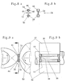
- FIGS. 4a and 4b a positioning part 34 with guide rollers 44, pins 56 and connecting part 50 is shown, as is used in FIGS. 1 to 3b.
- a sealing set 32 is shown in longitudinal section, in the positioning parts 34 of which lugs 52 are attached to hold the sealing rod 36.
- a sealing rod 36 with a longitudinal bore 60 is shown, which is rotatably mounted on a guide shaft 62.
- the lateral ends of the guide shaft 62 are held in bores 54 of the guide rollers 44.
- a sealing set 32 which consists of a positioning part 34, two guide shafts 62, two sealing rods 36 and two rotatably mounted relief rollers 88.
- the positioning part 34 is additionally supported on the rotary piston circumferential surfaces 30 via the relief rollers 88 and thus reduces the friction.
- a positioning part 34 is shown, as is used in FIGS. 7a-7b and 9a-9b.
- the guide rollers 44 connected via a connecting part 50 have bores 54 for receiving guide shafts 62 or pins.
- a seal set 32 with two mutually parallel sealing rods 36 is shown, the sealing rods 36 being rotatably supported in the bores 54 of the guide rollers 44 by machined pins.
- a seal set 32 is shown with a rotatably mounted sealing rod 36 and a positioning part 34, the guide rollers 44 of which are guided in grooves 64, which are worked into the rotary piston peripheral surfaces 30 with the same depth everywhere.
- Figure 10a and Figure 10b are drawn with the values of the practical embodiment on a scale of 1: 1.
- FIGS. 11a and 11b which, apart from the rotatably mounted relief rollers 88, is constructed as in FIGS. 10a and 10b, the advantages of reduced friction result as in the exemplary embodiment according to FIGS. 7a and 7b.
- a seal set 32 is shown, which is constructed similarly to that in FIGS. 10a and 10b, but with two sealing rods 36 and rounded portions 80 in the groove base 68.
- the guide rollers 44 also have correspondingly suitable curves.
- the respective grooves 64 have the same cross-sectional profile 76 throughout their course.
- a seal set 32 with two rotatably mounted sealing rods 36 and two positioning parts 34 is shown, the guide rollers 44 of which are guided in steps 66 which are attached to the rotary piston end faces 12.
- the steps 66 in the step base 70 have fillets 82, which in particular facilitates the production in the manufacturing process.
- the guide rollers 44 also have correspondingly rounded curves.
- a sealing set 32 is shown, which is constructed similarly to FIG. 13a and FIG. 13b, but which has rotatable sealing rods 36 with longitudinal bores 60, in which guide shafts 62 are mounted, the ends of which are in bores 54 of the guide rollers 44 are held.
- a seal set 32 is shown, which is constructed similarly to that in FIGS. 13a and 13b, but whose sealing rods 36 are roller-mounted in the guide rollers 44, the roller bearings being sealed by sealing disks 58 and the steps 66 being none Have fillets 88.
- the respective stages 66 have the same cross-sectional profile 78 throughout.
- a sealing set 32 is shown, the sealing rods 36 of which are rotatably mounted on the guide rollers 44.
- the sealing rods 36 thus have a larger outer diameter d than the circumferences 48, which limit the profile cross sections 46 of the guide rollers 44.
- the sealing rods 36 roll on the groove base 68 from the groove 64 machined into the rotary piston 10. Due to the enlarged sealing rod outer diameter d, the operating speed of the sealing rods 36 is advantageously reduced and their wear surface is increased.
- a sealing set 32 is also shown, the sealing rods of which are rotatably mounted on the guide rollers 44 and have larger outer diameters d than the circumferences 48 of the guide roller profile cross sections 46, the respective axial length of the sealing rods 36 being smaller than their outer diameter d.
- this advantageously reduces the movable masses.
Landscapes
- Engineering & Computer Science (AREA)
- Mechanical Engineering (AREA)
- General Engineering & Computer Science (AREA)
- Compressor (AREA)
- Hydraulic Motors (AREA)
Applications Claiming Priority (4)
| Application Number | Priority Date | Filing Date | Title |
|---|---|---|---|
| DE19601148 | 1996-01-15 | ||
| DE19601148 | 1996-01-15 | ||
| DE19603669 | 1996-01-29 | ||
| DE19603669A DE19603669C2 (de) | 1996-01-15 | 1996-02-02 | Rotationskolbenmaschine mit Dichtstangen |
Publications (2)
| Publication Number | Publication Date |
|---|---|
| EP0784147A1 true EP0784147A1 (fr) | 1997-07-16 |
| EP0784147B1 EP0784147B1 (fr) | 2001-07-18 |
Family
ID=26022054
Family Applications (1)
| Application Number | Title | Priority Date | Filing Date |
|---|---|---|---|
| EP97100099A Expired - Lifetime EP0784147B1 (fr) | 1996-01-15 | 1997-01-07 | Machine à piston rotatif |
Country Status (2)
| Country | Link |
|---|---|
| US (1) | US5860802A (fr) |
| EP (1) | EP0784147B1 (fr) |
Families Citing this family (2)
| Publication number | Priority date | Publication date | Assignee | Title |
|---|---|---|---|---|
| WO2006099606A2 (fr) | 2005-03-16 | 2006-09-21 | Searchmont Llc. | Machines rotatives a base spherique a axe radial |
| US10006360B2 (en) * | 2015-05-06 | 2018-06-26 | Brian Schmidt | Rotary directional pressure engine |
Citations (5)
| Publication number | Priority date | Publication date | Assignee | Title |
|---|---|---|---|---|
| US1349882A (en) * | 1918-01-28 | 1920-08-17 | Walter A Homan | Rotary engine |
| FR657191A (fr) | 1928-07-09 | 1929-05-17 | Machine rotative | |
| US3809026A (en) | 1973-02-28 | 1974-05-07 | D Snyder | Rotary vane internal combustion engine |
| WO1988005119A1 (fr) * | 1986-12-31 | 1988-07-14 | Dietrich Densch | Machine a pistons rotatifs avec garnitures d'etancheite |
| US4934325A (en) * | 1988-12-23 | 1990-06-19 | Snyder Duane P | Rotary internal combustion engine |
Family Cites Families (2)
| Publication number | Priority date | Publication date | Assignee | Title |
|---|---|---|---|---|
| US2097881A (en) * | 1935-11-26 | 1937-11-02 | Milton S Hopkins | Rotary engine |
| US5341782A (en) * | 1993-07-26 | 1994-08-30 | W. Biswell McCall | Rotary internal combustion engine |
-
1997
- 1997-01-07 EP EP97100099A patent/EP0784147B1/fr not_active Expired - Lifetime
- 1997-01-15 US US08/784,122 patent/US5860802A/en not_active Expired - Fee Related
Patent Citations (6)
| Publication number | Priority date | Publication date | Assignee | Title |
|---|---|---|---|---|
| US1349882A (en) * | 1918-01-28 | 1920-08-17 | Walter A Homan | Rotary engine |
| FR657191A (fr) | 1928-07-09 | 1929-05-17 | Machine rotative | |
| US3809026A (en) | 1973-02-28 | 1974-05-07 | D Snyder | Rotary vane internal combustion engine |
| WO1988005119A1 (fr) * | 1986-12-31 | 1988-07-14 | Dietrich Densch | Machine a pistons rotatifs avec garnitures d'etancheite |
| EP0339034B1 (fr) | 1986-12-31 | 1992-08-05 | Dietrich Dipl.-Ing. Densch | Machine a pistons rotatifs avec garnitures d'etancheite |
| US4934325A (en) * | 1988-12-23 | 1990-06-19 | Snyder Duane P | Rotary internal combustion engine |
Also Published As
| Publication number | Publication date |
|---|---|
| US5860802A (en) | 1999-01-19 |
| EP0784147B1 (fr) | 2001-07-18 |
Similar Documents
| Publication | Publication Date | Title |
|---|---|---|
| EP0854987B1 (fr) | Boíte de vitesses et palier pour la même | |
| DE4209153C3 (de) | Welle-Nabe-Verbindung | |
| DE69502550T2 (de) | Profilanpassung für Vielwalzengerüste | |
| DE4042390C2 (de) | Gleichlauffestgelenk | |
| DE69709199T2 (de) | Innenzahnradmotor | |
| EP0991871B1 (fr) | Dispositif comportant un arbre pourvu d'au moins un moyeu, ainsi que procede pour la fabrication de ce dispositif | |
| DE10082339B4 (de) | Antriebsgelenk | |
| DE4112291C2 (fr) | ||
| EP0353407B1 (fr) | Cage à doigts de séparation pour roulement à rouleaux de grande dimension | |
| DE69515181T2 (de) | Exzentergetriebe | |
| DE2146994A1 (de) | Einrichtung zum glattwalzen von kurbellagersitzen | |
| DE69215859T2 (de) | Dreibein-doppelgelenk mit rollen mit mehreren komponenten | |
| EP0149008A2 (fr) | Transmission planétaire | |
| DE3211612A1 (de) | Kreuzgelenk | |
| DE60017549T2 (de) | Verfahren zur Montage einer Trommel sowie Trommel und Achse für eine Bürstenwalze | |
| DE3834441A1 (de) | Vorrichtung zur lastuebertragung mit einem laufelement und einem zapfen sowie verfahren zur herstellung | |
| EP0784147B1 (fr) | Machine à piston rotatif | |
| DE3005694A1 (de) | Abdichtung am umfang eines laeufers einer rotationskolbenmaschine | |
| DE19603669C2 (de) | Rotationskolbenmaschine mit Dichtstangen | |
| DE2626800C3 (de) | Federgelenk bzw. Federkardangelenk | |
| DE19824069A1 (de) | Getriebe | |
| DE19513633C2 (de) | Dr}ckrolle zur Ausf}hrung von Spaltvorg{ngen | |
| EP4299935B1 (fr) | Galet tripode pour un joint tripode et joint tripode pourvu de ce galet tripode | |
| DE4229251A1 (de) | Rollenkupplung | |
| DE2421304A1 (de) | Parallel- und innenachsige rotationskolbenmaschine, insbesondere kraftmaschine oder pumpe, mit kaemmeingriff |
Legal Events
| Date | Code | Title | Description |
|---|---|---|---|
| PUAI | Public reference made under article 153(3) epc to a published international application that has entered the european phase |
Free format text: ORIGINAL CODE: 0009012 |
|
| AK | Designated contracting states |
Kind code of ref document: A1 Designated state(s): CH DE FR GB IT LI NL |
|
| 17P | Request for examination filed |
Effective date: 19980107 |
|
| GRAG | Despatch of communication of intention to grant |
Free format text: ORIGINAL CODE: EPIDOS AGRA |
|
| 17Q | First examination report despatched |
Effective date: 20000426 |
|
| GRAG | Despatch of communication of intention to grant |
Free format text: ORIGINAL CODE: EPIDOS AGRA |
|
| GRAG | Despatch of communication of intention to grant |
Free format text: ORIGINAL CODE: EPIDOS AGRA |
|
| GRAH | Despatch of communication of intention to grant a patent |
Free format text: ORIGINAL CODE: EPIDOS IGRA |
|
| GRAH | Despatch of communication of intention to grant a patent |
Free format text: ORIGINAL CODE: EPIDOS IGRA |
|
| GRAA | (expected) grant |
Free format text: ORIGINAL CODE: 0009210 |
|
| AK | Designated contracting states |
Kind code of ref document: B1 Designated state(s): CH DE FR GB IT LI NL |
|
| PG25 | Lapsed in a contracting state [announced via postgrant information from national office to epo] |
Ref country code: NL Free format text: LAPSE BECAUSE OF FAILURE TO SUBMIT A TRANSLATION OF THE DESCRIPTION OR TO PAY THE FEE WITHIN THE PRESCRIBED TIME-LIMIT Effective date: 20010718 |
|
| REG | Reference to a national code |
Ref country code: CH Ref legal event code: EP |
|
| REF | Corresponds to: |
Ref document number: 59704045 Country of ref document: DE Date of ref document: 20010823 |
|
| ITF | It: translation for a ep patent filed | ||
| ET | Fr: translation filed | ||
| REG | Reference to a national code |
Ref country code: GB Ref legal event code: IF02 |
|
| GBT | Gb: translation of ep patent filed (gb section 77(6)(a)/1977) |
Effective date: 20011130 |
|
| NLV1 | Nl: lapsed or annulled due to failure to fulfill the requirements of art. 29p and 29m of the patents act | ||
| PG25 | Lapsed in a contracting state [announced via postgrant information from national office to epo] |
Ref country code: LI Free format text: LAPSE BECAUSE OF NON-PAYMENT OF DUE FEES Effective date: 20020131 Ref country code: CH Free format text: LAPSE BECAUSE OF NON-PAYMENT OF DUE FEES Effective date: 20020131 |
|
| PLBE | No opposition filed within time limit |
Free format text: ORIGINAL CODE: 0009261 |
|
| STAA | Information on the status of an ep patent application or granted ep patent |
Free format text: STATUS: NO OPPOSITION FILED WITHIN TIME LIMIT |
|
| 26N | No opposition filed | ||
| REG | Reference to a national code |
Ref country code: CH Ref legal event code: PL |
|
| PGFP | Annual fee paid to national office [announced via postgrant information from national office to epo] |
Ref country code: IT Payment date: 20060131 Year of fee payment: 10 |
|
| PGFP | Annual fee paid to national office [announced via postgrant information from national office to epo] |
Ref country code: DE Payment date: 20060726 Year of fee payment: 10 |
|
| PGFP | Annual fee paid to national office [announced via postgrant information from national office to epo] |
Ref country code: GB Payment date: 20060727 Year of fee payment: 10 Ref country code: FR Payment date: 20060727 Year of fee payment: 10 |
|
| PG25 | Lapsed in a contracting state [announced via postgrant information from national office to epo] |
Ref country code: DE Free format text: LAPSE BECAUSE OF NON-PAYMENT OF DUE FEES Effective date: 20070801 |
|
| GBPC | Gb: european patent ceased through non-payment of renewal fee |
Effective date: 20070107 |
|
| REG | Reference to a national code |
Ref country code: FR Ref legal event code: ST Effective date: 20070930 |
|
| PG25 | Lapsed in a contracting state [announced via postgrant information from national office to epo] |
Ref country code: GB Free format text: LAPSE BECAUSE OF NON-PAYMENT OF DUE FEES Effective date: 20070107 |
|
| PG25 | Lapsed in a contracting state [announced via postgrant information from national office to epo] |
Ref country code: FR Free format text: LAPSE BECAUSE OF NON-PAYMENT OF DUE FEES Effective date: 20070131 |
|
| PG25 | Lapsed in a contracting state [announced via postgrant information from national office to epo] |
Ref country code: IT Free format text: LAPSE BECAUSE OF NON-PAYMENT OF DUE FEES Effective date: 20070107 |